
User Guide


OAS Sensor N/A
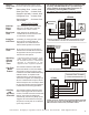
Once the programming is complete and the System is
functioning, the LCD screen will scroll and display the following
data continuously. The HVAC system mode of operation is
displayed including Supply Air and Outdoor Air temperature,
Auxiliary/Emergency mode and Ancillary Functions. The UT3000
LCD will continuously Scroll data as to which Zones are actively
calling for a Heating, Cooling or Fan Operation. By watching the
LCD display you can observe all system functions as they occur.
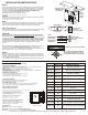
If desired, you can lock the LCD on a single screen by pushing
the Program Up & Down buttons at the same time. Select the
screen you want to watch with the Up button. The screen will stay
locked for 10 minutes then resume scrolling, or you can unlock
the screen by pushing the Forward button.
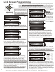
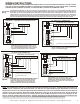
Below are LCD screen examples:
Zone 1 is calling for Heat @33% including Fan, so
the Fan demand is also 33%. This indicates the
presence of a Communicating Thermostat in Zone 1
whose demands are given a weighted value. (30% - 60%)
Zone 2 is calling for Heat @50% including Fan, so
the Fan demand is also 50%. This indicates the
presence of a Regular 24v HP T-stat in Zone 2 whose
demands are given a weighted value. (50% - 100%)
Zone 3 is calling for Cooling @100% including Fan,
so the Fan demand is also 100%. This indicates the
presence of a Regular H/C Thermostat in Zone 3
whose demands are given a weighted value. (0% - 100%)
IMPORTANT NOTE: You cannot mix 24V HP
Thermostats with 24V Heat/Cool Thermostats. The LCD
screens shown above are examples only. A Typical
installation may have a Communicating T-stat in Zone 1
and the rest may be 24v Heat Pump type.
Acceptable UT3000 Thermostat Combinations:
Zone 1 = Communicating
Zone 2 = Communicating
Zone 3 = Communicating
Zone 1 = Communicating NOTE: The Comm T-stat could be in any Zone!
Zone 2 = 24v H/C
Zone 3 = 24v H/C
Zone 1 = Communicating NOTE: The Comm T-stat could be in any Zone!
Zone 2 = 24v HP
Zone 3 = 24v HP
Zone 1 = 24v H/C
Zone 2 = 24v H/C
Zone 3 = 24v H/C
Zone 1 = 24v HP
Zone 2 = 24v HP Refer to Page 9 for Sample Thermostat Diagrams
Zone 3 = 24v HP
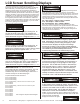
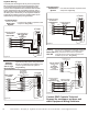
This screen displays the SYSTEM (SYS) Output percentage to the
HVAC Equipment. In this Heat Pump Example, the UT3000 is
demanding 25% heating capacity and 25% fan capacity. That means
1st stage heat (Y1) is active. If the HP Target set-point (110F) is not
satisfied before reaching 51% SYS Output, Y2 will energize. If the
HP target set-point is not satisfied before reaching the W2 threshold
value, W2 will energize.
0% - 50% Output = Y1HP or Y1A/C or W1Gas
51% - 65% Output = Y2HP or Y2A/C
W2 Threshold 65% - 99% = W2HP or W2Gas
Note: The UT3000 may interpret a Thermostat input as 100%
demand but it will not Output a 100% System Demand. The UT3000
will demand only as much System Capacity as is necessary, to
satisfy the Supply Air Target Set- Points. Any single calling zone is
considered to be a 33% demand.
This screen displays the System Percentage demand
from the Auxiliary and/or the Emergency system. The
Aux will display a value during Auxiliary mode. Both
screens will display values during Emergency mode.
The next screen displays the System Percentage
demand to Humidify or De-humidify. Humidify demands
may come from a Communicating thermostat or 24v Rh Control.
The UT3000 only honors De-Humidify demands from
Communicating thermostats on Communicating systems.
This screen shows the real time supply air temperature
at the location of the supply air sensor. The UT3000
monitors and compares the Supply Air Temperature to
the Heat Pump Target, Cooling Target or Gas Target
Set-points. The UT3000 will increase or decrease the
SYS Demand Output in order to match the Target SP.
If the Supply Air Sensor fails or is disconnected, the
UT3000 will display the “Bad Sensor” screen. If this
happens the UT3000 will default to “Timed Mode” and
steadily increase the System Demand output until 100%
is reached or the T-stat demands are satisfied.
This screen shows the real time outside air temperature
at the location of the outside air sensor. This OA value
could be from the Communicating HVAC system or from
a Sensor connected to the UT3000. If the OAS sensor
fails or is disconnected , the UT3000 will display the
“Bad Sensor” screen and will default to emergency
mode. If you do not want to use an OAS Sensor to stage the
system, adjust the OAS SP (Set-Point) value down to the OFF
position and the UT3000 will
display the screen to the right.
LCD Screen Scrolling Displays
5
EWC Controls Inc. 385 Highway 33 Englishtown, NJ 07726 800-446-3110 FAX 732-446-5362 E-Mail- info@ewccontrols.com
! OAS Sensor Bad !
Z1 h030c000f030
Z3 h000c100f100
Supply TMP 147
! SAS Sensor Bad !
Z2 h050c000f050
SYS Aux100 Em100
SYS Hum000 Dh015
Outside TMP 32
SYS h025c000f025