
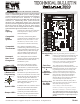
User Guide


Y
R
G
C
W/E
O/B
2
ZONE
9
EWC Controls Inc. 385 Highway 33 Englishtown, NJ 07726 800-446-3110 FAX 732-635-8646 E-Mail- info@ewccontrols.com
WARNING: THESE PANELS ARE DESIGNED FOR USE WITH 24VAC. DO NOT USE OTHER VOLTAGES! USE CAUTION TO AVOID
ELECTRIC SHOCK OR EQUIPMENT DAMAGE. ALL WORK SHOULD BE PERFORMED TO LOCAL AND NATIONAL CODES AND
ORDINANCES. USE 18 AWG SOLID COPPER, COLOR-CODED, MULTI-CONDUCTOR THERMOSTAT CABLE.
Thermostat
Wiring
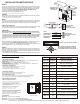
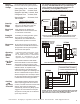
WIRING INSTRUCTIONS
Model EWT-3707 Thermostat Configured for 1 heat &
1 cool (SS1 mode). See thermostat instructions for
details. The HVAC system equipment may be 24v
Legacy or Communicating type.
Figure 2c
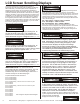
Communicating thermostats can be used on all zones for all applications. You can also mix Communicating thermostats with 24v
thermostats. Just make sure you select the correct type of 24thermostat in the program menu. You cannot mix 24v Single stage heat/cool
thermostats with 24v Heat Pump thermostats. A Comm LED is provided at each Comm Terminal Block to indicate a Link has been
established with each communicating device. The Comm LED will pulse rapidly & randomly to indicate the Link is active. Otherwise it
will blink very slow. Be patient and allow sufficient time for all Communicating T-stats to finish the configuration process. Usually 60
seconds or less. Make sure to allow enough time for the entire HVAC system to access the network. Usually no more than 3 minutes.
Figure 2d
NOTE: The UT3000 allows the user to install Communicating Thermostats on all zones. Communicating thermostats can
also be used in combination with 24v thermostats. You may also use regular Heat/Cool type thermostats or Heat Pump
thermostats on all zones. This design simplifies the thermostat selection process and allows the installer to easily adapt the
UT3000 to most any residential application. NOTE: Regardless of the type of 24v thermostats used, the W2 Threshold
feature or the OAS Set-Point will control the auxiliary system. Once the W2 Threshold is crossed or the Outdoor Air Set-
Point is reached, Auxiliary Heat will energize. Auxiliary demands from each thermostat are only used to determine the
weight or percentage of demand from that zone, rather than immediately activating Auxiliary operations.
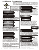
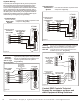
24v HEAT PUMP THERMOSTAT
Figure 2b
*
Field installed jumper.
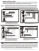
Figure 2a
24v HEAT/COOL THERMOSTAT
C
O/B
E
L
W1
W2
Y1
R
G
Model EWT-3102 Thermostat
**
C
O B
E
L
W1
W2
Y1
R
G
Wireless Thermostat: Receiver Module
Model EWT-3900
*
Common wire not required if batteries are used.
*
Model EWT-3900 Wireless Thermostat.
Configured for 1 heat 1 cool (SS1 mode). Can be
configured for heat pump also. See thermostat
instructions for details. Use Wireless thermostats in
Zone 2 and/or Zone 3. Always use a hard wired type
thermostat for Zone 1.
*
OEM Mfr’s Communicating Thermostat. See
thermostat instructions for further details. You can
use communicating thermostats on every zone. Or
use a communicating thermostat in Zone 1 and less
expensive 24v thermostats in Zone 2 and Zone 3.
C
W/E
Y
R
G
ONE
ZONE
O/B
1
ZONE
DRY R
R
R
Model EWT-3102 Thermostat Configured for 2 heat &
1 cool (HP1 mode). See thermostat instructions for
details. The HVAC system equipment may be 24v
Legacy or Communicating. You can also mix 24v
type thermostats and communicating thermostats.
C
O
B
E
L
W1
W2
Y1
R
G
Model EWT-3707 Thermostat
*
*
Common wire not required if batteries are used.
C
W/E
Y
R
G
ONE
ZONE
O/B
1
ZONE
DRY R
R
LED
LED
LED
ZONE
2
C
R
2
1
C
2
1
R
ClimateTalk™ Compatible Communicating Thermostat
C
W/E
PO
LED
White
Yellow
Green
Red
Figure 2b
C
W/E
Y
R
G
ONE
ZONE
O/B
1
ZONE
DRY R
R
LED