(;% DQG (;% &DUWULGJH 7DSH 6XEV\VWHP 6WDQGDUG DQG DQG H;WHQGHG OHQJWK FRQILJXUDWLRQV ,QVWDOODWLRQ DQG 2SHUDWLRQ 302967-001
Copyright Copyright 1993-1994 by Exabyte Corporation. All rights reserved. This item and the information contained herein are the property of Exabyte Corporation.
Product Warranty Caution The EXB-8205, EXB-8205XL, EXB-8505, and EXB-8505XL 8mm Cartridge Tape Subsystems (tape drives) are warranted to be free from defects in materials, parts, and workmanship and will conform to the current product specifications upon delivery. For the specific details of your warranty, refer to your sales contract or contact the company from which the tape drive was purchased.
Contents Welcome . . . . . . . . . . . . . . . . . . . . . . . . . . . . 5 About This Guide . . . . . . . . . . . . . . . . . . . . . . . 6 Conventions Used in This Guide . . . . . . . . . . . . . . . . . 6 For More Information . . . . . . . . . . . . . . . . . . . . . . . 6 1 Installing the tape drive . . . . . . . . . . . . . . . . . . . 7 Unpacking and Handling the tape drive . . . Setting the SCSI ID . . . . . . . . . . . . . Preparing the Tape Drive for the SCSI Bus .
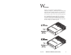
W elcome Thank you for selecting the Exabyte® EXB-8205, EXB-8205XL, EXB-8505, or EXB-8505XL8mm Cartridge Tape Subsystem (tape drive). These tape drives are high-capacity, high-performance, and highly reliable storage devices for PC, workstation, and local area network (LAN) applications. The “eXtended-Length” (XL) configurations of the tape drives (EXB-8205XL and EXB-8505XL) provide additional capacity by supporting the extended-length EXATAPE™ 160m XL 8mm Data Cartridge.
About This Guide Use this guide as you install and operate the tape drive. In addition to instructions for installation and operation, this guide provides information about selecting and maintaining data cartridges, cleaning the tape drive, and packing the tape drive for shipment. Conventions Used in This Guide Special information is highlighted as follows: Note: Notes provide hints or suggestions about the topic or procedure being discussed.
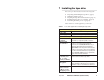
1 Installing the tape drive This section provides instructions for the following tasks: ■ ■ ■ ■ ■ Unpacking and handling the tape drive (page 8) Setting the SCSI ID (page 9) Preparing the tape drive for the SCSI bus (page 11) Installing the tape drive in a computer (page 13) Performing the initial power on (page 18) Table 1 lists the tools and equipment you will need.
Unpacking and Handling the tape drive The tape drive’s packaging is designed to protect the tape drive from shock, vibration, moisture, and electrostatic discharge (ESD). Save all original packaging in case you need to repack or ship the tape drive. If the temperature of the room in which you are unpacking the tape drive varies from the storage location by 15° C (27° F) or more, let the tape drive acclimate in its packaging to the unpacking environment for at least 12 hours before opening the box.
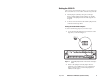
Setting the SCSI ID After you have unpacked the tape drive, you can set the tape drive’s SCSI ID. You can use either of the following methods: ■ Attach jumpers (shunts) to the pins on the tape drive’s SCSI ID jumper block. Jumpers are already installed on the jumper block when the tape drive is shipped. ■ Connect a remote switch to the SCSI ID jumper block on the back of the tape drive. Setting the SCSI ID with Jumpers To set the SCSI ID using jumpers, follow these steps: 1.
Figure 2 Jumper settings for the tape drive’s SCSI ID Setting the SCSI ID with a Remote Switch If you want to set the SCSI ID remotely, you can attach a remote switch assembly (not provided with the tape drive) to the tape drive’s SCSI ID jumper block. To set the SCSI ID with a remote switch, follow these steps: 1. Locate the SCSI ID jumper block on the back of the tape drive, as shown in Figure 1. 2. If necessary, remove the jumpers from the pins. 3. Connect a remote switch to the jumper block.
Preparing the Tape Drive for the SCSI Bus The SCSI bus that you attach the tape drive to must be terminated correctly to ensure proper operation. The devices that are physically located at each end of the SCSI cable must have terminators installed. All other devices on the SCSI cable must not have terminators installed. If you place the tape drive at the end of the SCSI bus, you must terminate the tape drive.
Figure 3 Location of R-packs on the back of the tape drive (single-ended configuration) Replacing the R-Packs If you need to put the R-packs back in the tape drive, make sure that pin 1 of each R-pack is aligned with pin 1 of the socket and that no pins are bent. As shown in Figure 3, the writing on the R-pack should face upward. Pin 1 of the R-pack is marked with a colored line or dot and should line up with the right side of the socket.
Connecting the SCSI Cable After removing or installing terminators as required, connect the SCSI cable to the SCSI connector on the back of the tape drive. The connector is keyed so that it can be connected only one way. Figure 4 shows the location of the SCSI connector. See Appendix A starting on page 36 for information about the requirements for the SCSI cable.
4. If there is a cover plate over the drive bay you plan to use, remove it. Refer to your computer system documentation for instructions. Keep any screws or mounting clips; you may need them to secure the tape drive to the drive bay. Note: If necessary, remove a floppy disk drive to provide an empty half-high drive bay for the tape drive. Refer to your computer system documentation for instructions. Do not replace your floppy drive A with the tape drive.
Figure 5 Figure 6 May 1994 Attaching slide rails to the tape drive 3. From the front of the computer, thread the SCSI cable through the open drive bay, as shown in Figure 6. Slide the tape drive into the bay until the front of the drive is flush with the front of the drive bay. 4. Connect the SCSI cable to the SCSI adapter card in your computer.
5. Slide the tape drive into the drive bay and secure the drive to the bay as instructed in you computer system documentation. 6. If you needed additional chassis grounding, connect a 1⁄4-inch female spade connector to the ground tab at the rear of the tape drive. Or, connect an M3-0.5 6 mm self-tapping screw to the grounding hole. The ground tab and grounding hole are shown in Figure 7.
7. Locate the power connector on the back of the tape drive. Connect the power cable to the power connector as shown in Figure 8. CAUTION The power cable plug and the power connector are keyed so they can fit together in only one way. Before connecting the plug to the tape drive, be sure that the beveled edges of the plug are oriented in the same way as the beveled edges on the power connector. Do not force the plug into the connector or you may damage the tape drive. 8.
Performing the Initial Power On The procedure you use to perform the initial power on depends on how long the tape drive has been stored. If you are not sure how long the tape drive has been stored, check the MLCH (machine level control history) label on the top of the tape drive to find out when the tape drive was manufactured. Although the tape drive may have been operated since it was manufactured, for the purpose of the initial power on, assume that it has been stored throughout this period.
Tape Drive Stored for Six Months or More If the tape drive has been stored for six months or more, perform the following steps using your backup software to ensure that the tape drive’s internal lubrication is properly distributed: 1. Apply power to the tape drive. The tape drive performs its POST as described on page 18. 2. Locate a test tape and ensure that the write-protect switch is set to permit data to be written to the tape (see page 25). 3.
2 Operating the tape drive This section includes information about the following: ■ ■ ■ ■ Reading the LEDs Selecting data cartridges Setting the write-protect switch on the data cartridge Loading and unloading a data cartridge Figure 9 shows the controls and indicators on the front panel of the EXB-8505. (Note that the front panel of the EXB-8205 is the same except the LEDs are vertical. The XL drives are the same as the non-XL drives except that they have a raised diamond pattern on the unload button.
Reading the LEDs The tape drive uses three LEDs to indicate its operating states. The LEDs indicate the following general conditions: ■ When the top (amber) LED is flashing, the tape drive has an error or needs to be cleaned. ■ When the middle LED is on or flashing, SCSI bus activity is occurring. The middle LED can be green or amber, as follows: ■ Amber: The tape loaded in the tape drive is in one of the compression formats (8500c or 8200c).
Table 2 tape drive states indicated by the LEDs Middle (SCSI)b Bottom (motion) j ❍ ❍ ❍ ● Time to Clean ❍ Error fast SCSI bus reset ● High-speed tape motion ● Normal tape motion Top (errors) Failed POST j = Flasha POST (end) ❍ = Off POST (start) ● = On Ready (tape loaded) LEDs Ready (no tape loaded) Tape Drive State slow fast j j green irreg. irreg. irreg. irreg. irreg. irreg. irreg. irreg. irreg.
Selecting Data Cartridges By selecting high-quality data cartridges and storing them properly, you can expect a long shelf-life and optimal data integrity from your tapes. High quality tapes also help maintain tape drive reliability by minimizing wear on the recording heads. Choosing High-Quality Data Cartridges Available from Exabyte, EXATAPE™ 8mm Data Cartridges are formulated specifically for use in Exabyte products.
EXATAPE 160m XL 8mm Data Cartridges The EXATAPE 160m XL 8mm Data Cartridge is intended for use in the EXB-8502XL and EXB-8505XL only. The 160m XL tape is equipped with a Recognition System stripe, located on the tape leader, that enables the XL tape drive to recognize the tape as data-quality metal-particle media. To prevent the use of inappropriate media, the EXB-8205XL and EXB-8505XL do not accept 160m tapes without the Recognition System stripe.
Setting the Write-Protect Switch on a Data Cartridge EXATAPE™ 8mm data cartridges are equipped with a write-protect switch, shown in Figure 10, to prevent data on the tape from being unintentionally overwritten. Before loading a data cartridge in the tape drive, ensure that the write-protect switch is set correctly for the desired operation.
Loading a Data Cartridge in the tape drive Important Exabyte strongly recommends that you use EXATAPE™ data-grade metal-particle media in the tape drive. Refer to page 23 for information about selecting appropriate tapes for your tape drive. To load a data cartridge into the tape drive, follow these steps: 1. Ensure that the write-protect switch has been set correctly for the desired operation, as explained on page 25. 2.
Unloading a Data Cartridge The unload button is the only operator control on the tape drive. It is used to unload the tape from the tape drive. The unload button can also be used to clear servo and other errors. If a servo or hardware error occurs, press the unload button to reset the tape drive. Then, if necessary, wait a few seconds and press the button again to eject the tape. Unload Procedure To unload a data cartridge, press the unload button on the tape drive’s front panel.
3 Preventive Maintenance The only routine maintenance required by the tape drive is regular cleaning of the tape drive’s heads and tape path. The only cleaning material authorized for use with the tape drive is an Exabyte or Exabyte-approved 8mm Cleaning Cartridge. In addition, proper storage and maintenance of your data cartridges will maximize the shelf life of you tapes and ensure data integrity.
Using the 8mm Cleaning Cartridge Exabyte 8mm Cleaning Cartridges are available in two sizes: 3c and 12c. Used in the EXB-8205, EXB-8505, or XL tape drives, the 3c cleaning cartridge provides up to 9 cleanings. The 12c cleaning cartridge provides up to 36 cleanings. Note: If you use these cleaning cartridges in an Exabyte full-high tape drive (EXB-8200, EXB-8200SX, EXB-8500, or EXB-8500c), you will get fewer cleaning passes per cartridge.
3. To confirm that a cleaning was done, check the LEDs on the front panel. If the cleaning cycle was successful, the top and bottom LEDs will be off. If the cleaning cycle was not performed, the LEDs will continue to flash. Repeat the cleaning procedure with a new cleaning cartridge. 4. If the cleaning cycle was successful, you may want to keep a record of the date the cleaning was performed. Store the cleaning cartridge for future use if it still has cycles remaining.
■ Figure 11 Store each cartridge on one of its long edges, not flat on its side (see Figure 11 on the following page). When a data cartridge is stored on its side, the tape inside the cartridge is actually on its edge. In this position, stress is placed on the tape edges and can lead to tape damage. For the same reason, never stack cartridges on top of each other or lean them at an angle for extended periods of time.
4 Shipping the Tape Drive You can ship the tape drive with either one drive per carton (single-pack) or with three to five drives per carton (multi-pack). Figure 12 on page 34 shows the single-pack carton and packing materials; Figure 13 on page 35 shows the multi-pack carton and packing materials. CAUTION ■ To avoid damaging the tape drive and voiding your warranty, be sure to use the original shipping materials (or replacement materials obtained from Exabyte) when repacking and shipping the tape drive.
Packing the Tape Drive To pack the tape drive for shipment, follow these steps: 1. Obtain the original shipping carton or contact your vendor to receive a new one. 2. Assemble the carton and tape it shut at the bottom with two-inch (51 mm) packing tape. 3. Place each tape drive in an antistatic bag. Tape the bag shut. 4. Place the bottom packing cushion in the carton, with the fitted area for the drive or drives facing up. 5.
Figure 12 34 Single-pack carton and packing materials EXB-8205 and EXB-8505 (Standard and XL) 302967
Figure 13 Multi-pack carton and packing materials Environmental Requirements for Shipment When shipping a tape drive, be sure to comply with the environmental specifications shown in Table 5. Table 5 Environmental specifications for shipping the tape drive Temp. Range -40° C to +60° C (-40° F to +140° F) Temp. Variation 1° C per minute up to a maximum of 20° C per hour (2° F per minute up to a maximum of 36° F per hour) Rel.
Appendix A Installation Requirements This appendix lists the requirements for the following items: SCSI cable ■ ■ ■ SCSI connector Power cable Power connector It also provides guidelines for attaching the tape drive to a frame and adding optional chassis grounding. SCSI Cable The SCSI cable for connecting the tape drive to the host is not provided with the tape drive. You must provide a cable that complies with the appropriate safety and regulatory agency requirements.
Cable Length Requirements for Differential Configurations For differential SCSI configurations, ensure that the sum of all the SCSI cable lengths does not exceed 25.0 meters (82.02 feet). A stub length of no more than 0.2 meters (8 inches) is allowed off the mainline interconnection within any connected equipment. The stub length within the tape drive is less than 50 mm (1.97 inches).
Power Supply The tape drive operates from standard +5 VDC and +12 VDC supply voltages; it does not use external AC power. Safety agency certification requires that the supplied voltage be from a Safety Extra-Low Voltage source (per IEC 950). CAUTION The tape drive does not provide any overvoltage or overcurrent protection. For this reason, be sure that the power is off before connecting the tape drive to power.
Attaching the tape drive to a Frame The main housing of the tape drive includes three sets of mounting holes (two sets on the sides and one set on the bottom, as shown in Figures 14 and 15) to allow for a number of mounting positions. These mounting holes accommodate M3 5 6 mm screws. Refer to the EXB-8205 and EXB-8505 Product Specification for detailed information about the spacing of these mounting holes.
Figure 14 Mounting holes on the sides of the tape drive Figure 15 Mounting holes on the bottom of the tape drive 40 EXB-8205 and EXB-8505 (Standard and XL) 302967
Chassis Grounding (Optional) If you needed additional chassis grounding, connect a 1⁄4-inch female spade connector to the ground tab at the rear of the tape drive. Or, connect an M3-0.5 6 mm self-tapping screw to the grounding hole. The ground tab and grounding hole are shown in Figure 7 on page 16. Note: The power supply returns are connected to the chassis, so you cannot isolate logic common ground from chassis ground.
Appendix B Unload Button Options Depending on how your tape drive has been configured, the unload button functions in one of three ways: ■ ■ ■ As a “normal” unload button (default) As a “fast” unload button As a “super fast” unload button Table 7 summarizes the actions that occur with the three unload button options. For further details about these three options, refer to the EXB-8205 and EXB-8505 8mm SCSI Reference.
Note: With the “super fast” unload button, the tape drive will unload the tape even if an error is present during the unload procedure, unless the error is a serious hardware error as follows: The tape drive is unable to remove the tape from the tape path and spool all of it into the cartridge. In this case, the tape drive does not eject the cartridge. This prevents the cartridge lid from closing on the exposed tape. ■ ■ May 1994 The front load motor is not functioning.
Appendix C Tape Drive Specifications General Interface SCSI-1 and SCSI-2, single-ended or differential Mean time between failure 160,000 hours Physical Characteristics Form factor 5.25-inch half-high Size 4.1 cm high 14.6 cm wide 20.3 cm deep (1.62 5.75 8.00 inches) Weight 1.2 kilograms (2.6 pounds) Environmental Operating temperature +5°C to +40°C (+41°F to +104°F) Operating Rel.
Index J C L jumpers for setting SCSI ID cable requirements power cable 38 SCSI cable 36 – 37 cartridges see data cartridges cartridge tape subsystem see tape drive chassis grounding 41 cleaning the tape drive frequency 28 instructions 29 – 30 time-to-clean LED 28 condensation 8 CTS see tape drive LEDs location 20 states indicated by 21 – 22 time-to-clean indication 28 load procedure 26 M maintenance 28 – 30 mounting requirements operating the tape drive packing the tape drive 32 – 35 power cable req
U unload button location 20 options 27, 42 unload procedure 27, 42 unpacking instructions 8 W write-protect switch 25 X XL (eXtended-Length) 160m data cartridge tape drives 5 46 24 EXB-8205 and EXB-8505 (Standard and XL) 302967