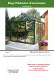
Royal Victorian Greenhouse VI23,34,36,46 Version 2020_3 12.08.20 MOUNTING INSTRUCTIONS Note: This is an all-inclusive manual. It shows optional accessories and customizations that may not apply to your greenhouse. Direct any questions to Exaco. www.exaco.com 877-760-8500 Please watch our animated assembly video on our Exaco Trading Co YouTube Channel. Find the link at www.exaco.
PRODUCT INFORMATION Dear customer, Thank you for buying a Janssens high-quality aluminium greenhouse. REMARKS In this manual, you will find the assembly instructions for all basic/standard-model greenhouses. However, this manual also contains pages which apply to optional accessories that may not be included with your kit. This greenhouse is designed for cultivation of plants/flowers. Therefore leakage, water drops and condensation inside the building are allowed.
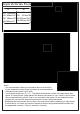
Royal Victorian Foundation Drawing A X VI23 2360mm/93" VI34 3098mm/122" VI36 3098mm/122" VI46 3836mm/151" B VI23 3098mm/122" VI34 4574mm/180" VI36 6050mm/ 238.2" VI46 6050mm/ 238.2" Note: Do not set anchors in concrete until the entire greenhouse frame is complete, level and square. You will need some play to attach the uprights. Notes: - It is recommended to build your foundation down to the frost line in your area and/or consult a local contractor for recommendations. - Greenhouse base frame is 2.
VI 34,36,46 with Stem Wall This page only applies when you have a door extension kit and are placing your greenhouse on a wall. (2020 HDD) Call for sliding door measurements! A = 3.098 | 3.836 B = 2.360 | 3.098 | 3.836 4.574 | 5.312 | 6.050 C = 829 | 1.567 | 2.305 D = 703 hinged door ONLY! E = 829 | 1.567 | 2.305 !!! A|B|C|E H 200 | 400 600 | 1.025 Call Exaco for sliding door measurements! A= C+D+E !!! A = 3.098 | 3.836 B = 2.360 | 3.098 | 3.836 4.574 | 5.312 | 6.050 C = 829 | 1.567 | 2.305 D = 1.
VI 23 on Stem Wall- One door on Gable Call for sliding door measurements! (shown with narrow panes) A = 2.360 B = 2.360 | 3.098 | 3.836 4.574 | 5.312 | 6.050 C = 829 D = 703 hinged door ONLY! E = 829 !!! A= C+D+E !!! A|B|C|E H 200 | 400 600 | 1.
4 pc 1830 mm 1830 mm 1230 mm 1230 mm 1900 mm 1975 mm PRO6578 corner profile PRO1456 glazing bar gable PRO6918 endbar roof PRO1456 glazing bar roof PRO10980 round tube Ø40 PRO21214 wind bracings gabel 2 pc 4 pc 10 pc 32 pc 2 pc 2 + 2 pc 2 pc DAKR_HEL 1 pc ZAK_H screw 4.8x38 DIN7504 N A2 bolt M6x25 DIN933 A2 screw 4.
Please note: You have a VI46 (H46) greenhouse. This section lists the parts for a standard greenhouse, but does not include all pieces for optional accessories. You may have parts in addition to what is listed here.
Royal Victorian Glass Sizes - 4mm thick (3/16") (VI23 7'9"x10'2") Roof 2 15/16" 21 3/8" 49 3/16" below louver Gable 43 1/4" 28 3/4" below vent 16 3/4" Side wall 72 3/4" Roof Vent & 32 1/2" 4 7/16" 28 3/4" 28 3/4" 28 3/4" (VI34 10'2" x 15') 28 3/4" Roof Vent & below vent & below louver 28 3/4" Gable 28 3/4" 28 3/4" 28 3/4" 28 3/4" 27 3/8" 28 3/4" 28 3/4" Roof Vent & below vent & 28 3/4" Gable below louver 28 3/4" 32 1/2" Gable 16 5/16" 2 15/16" 16 3/16" Roof 4 7/16" 64 7/
PRO210 TRE PRO1456 PRO6578 PRO20229 Ø 19 PRO6760 Page: H_1 Key to Profile (Extrusion) Placement Note: Model pictured in entire manual is VI34 your size/layout may vary.
M6x15 0 612 612 0 PRO210 PRO PRO Note: When assembling the foundation in this step, only hand-tighten the nuts. The corners may needto be slightly loose to attach the corner uprights (PRO6578). M6x50 X A X B Suggestion: If installed on a concrete foundation you may cut PRO210 flush with the bottom of PRO6120. To anchor, use cut off PRO210 pieces as Lbrackets to secure the PRO6120 to the concrete foundation. Please see YouTube animated assembly video for more information.
Standard OPTION:SLIDING DOOR Double PRO29909 Single or Double Single Upgrade OPTION for Sliding Door: LOW THRESHOLD PRO29909 Upgrade OPTION: HINGED DOOR Note: Insert bolts now See pages H_52 (HD1 -HD10) for instructions See pages H_35 (H_34-36) for instructions Page: H_4 See pages H_37 (SDL1-2) for instructions
Optional: Insert a bolt into each corner post channel for where the top shelf and/or Seed Tray will be located. See page H_62 and H_63 for location information.
PR O2 02 29 M6x15 Page: H_6 PRO6578
M6x15 PR O2 02 27 Page: H_8 PRO6578 PR O2 02 29 OPTIONAL: If you purchased shade curtains, insert the slider loops into the gutter profile channel before this assembly step. See page H_64 for more information.
NOTE! Sliding doors will use PRO29909 for the door frame see H_34. PRO61 M6x15 PRO1456 20 ! B > 4m58 If length > 4580mm (i.e. VI36 and VI46) then insert 2 bolts in the center profile for Scroll Supports - see H_20 and H_21 for more information. 0227 Page: H_9 NOTE! Before securing vertical profiles insert bolts for: Louvered Window, see p. H_44-46 Optional Narrow Top Shelf, see p. H_62 Optional Seed Tray, see p.
PRO61 20 M6x15 TR E PRO1456 Page: H_10 PRO2 0227 PR O2 02 29
PRO2 0229 M6x15 Page: H_11 PRO1456 LG
M6x15 PRO6 Page: H_12 Insert bolts to connect short uprights to the PRO6918. You will need as many bolts as you have short uprights.
! Only for models over 2360mm (i.e. VI34, 36, 46) See p. H_17 PRO6 M6x15 760 Insert bolts into ridge beam: 2 for L brackets, 2 for diagonal supports (except VI23), and 3 for misting system. If you have the optional shadecloth insert sliders - see p. H_64-65 for count and placement.
PRO1456 M6x15 LG Page: H_14
M6x15 ! 56 56 M6x40 B > 4m58 PRO14 PRO14 M6x15 Page: H_15 If length > 4580mm (i.e.
PRO 676 PRO1456 Page: H_16 M6x15 0
! A 19 Ends of diagonal support will need to be bent appropriately. Ø Page: H_17 A > 2m36 Only for models over 2360mm (i.e.
B A A B A Placement of Roof Wind Braces (TRE) - View from above Attach first at ridge beam Page: H_18 B TRE TRE
B A A B A Placement of Roof Wind Braces (TRE) - View from above Attachment at gutter profile Page: H_19 B TRE TRE
! B Scroll Supports are included ONLY If length > 4580mm (i.e.
! ! PUSH 10MM Page: H_21 Very Important: Push the ridge beam up at least 10mm before tightening the scroll supports. 2 FIX 1 Scroll Supports are included ONLY If length > 4580mm (i.e.
SILIC ON E Page: H_22 SILI CO NE Note: Attach the elbow to the greenhouse base. First, drill a small hole in the back of the elbow and then a small hole in the frame of the greenhouse for the screw to thread into. Run the screw through the hole on the inside of the elbow and into the greenhouse base.
M6x15 PRO1 456 Page: H_23 Crossbar for framing roof vent opening. Roof Vents can be installed in any bay. Insert bolts to attach conntecting plate.
PR 4 O1 56 M16x15 PRO1456 PRO1456 PR O 5 14 6 M16x15 OPTIONAL: THIS PAGE ONLY APPLIES TO 'RETRO' MODEL PRO1456
4mm GLASS P 780 RO20 Glazing supports slide onto the gutter profile, space them 100mm or 4 inches from each roof profile.
HELIOS polycarbonate 10mm This page is for polycarbonate units only. The crescent seal (E400330) is NOT used with polycarbonate. It may be shipped with your unit, but it is only for GLASS panels. Remove the protective film, but leave the silver sealed tape and ventialtion tape on the ends. Ventilation tape indicates the bottom of the panel. The U-profiles are not used in the doors and windows.
1 3 3 2 Glazing shim installation: Install the glass panels then fix the shims to either side of the glass with a dab of silicon. Then install the rubber trim. Shims are only installed in end panels as shown below. Space the shims 100mm/4" from the top and bottom. Polycarbonate units will not use these shims. To install gasket, roll it back on 3 itself as shown. This exposes the inner flange that is pushed into the channel. It will be easier to insert 3 when warm and pliable.
SILIC ON E Page: H_27 E ON SILIC SILICO NE
E400330 PRO6918 Page: H_28 PRO20229 Crescent seal is only installed in PRO20227 the eaves and roof. Not along side walls.
E400330 PRO6760 1 2 PRO6918 Page: H_29 PRO1456 3 To install heavy gasket, it is easiest to roll it back on itself as shown. This exposes the inner flange that is pushed into the channel. It will be easier to insert when warm and pliable. Install the roof glazing pane by pane, inserting gaskets after each.
ACCESSORIES This section contains many of the optional accessories. You will have some, but likely not all, items seen in this section.
Sliding door (standard for most models) Some models will have double sliding doors. PRO6121 M16x15 PRO40352 E400330 Rubber seal is installed only on sides. If you have double sliding doors, the brush seal will only be installed on the outside edges.
Sliding Door PRO78 76 STOP PRO29909 STOP 120 PRO6 M16x15 6 3979 PRO Page: H_35
OPTION: Double Sliding Door NE O IC SIL OPTION PRO1456 PRO7876 Note: Apply upward pressure when installing the door support(in red). NE O IC SIL NE O IC SIL 4X 4X As needed, use washer underneath door hanger to level the door . 4X Page: H_36 Add L bracket to close the gap between the doors where they meet.
OPTION OPTION: Sliding Door Lowered Threshold Page: H_37 SDL1
OPTION OPTION: Sliding Door Lowered Threshold (cont'd) Page: H_38 SDL2
Note: A 1 inch long bolt is inserted into the lower profile. This bolt is for the optional manual or the spindle opener. 610 PRO7 15 PRO76 Page: H_39 RUBBER E400330 Note: Rubber seal is only installed on the sides of the roof window.
Page: H_40 Slide window into the ridge beam from either end of the greenhouse. The "hook" on the top of the roof window profile will slide into the channel of the ridge beam. Note: Inserting a bolt on either side of the roof window will prevent it from moving side to side . Standard manual opener shown (generally not installed). However, it may be used to secure the window in the closed position - auto opener MUST be detached.
Page: H_41 Installing the automatic opener requires 2 bolts to be inserted into the roof crossbar for the lower mount. The upper mount will clamp onto the window profile. (Shown to the right) Please read instructions included with the Ventomax auto opener to fully understand the functioning and maintenance of these unique openers.
Installation Option 2: Insert a 1 inch long bolt into lower roof window channel. Slide to the center and lock it in place with a nut as shown below. Installation Option 1: Mount top of opener to window with a screw Page: H_42 Next, hold the lower U-shaped mount up to the crossbar and mark the center of one hole. Using a 1/8" drill bit, drill the first hole, then screw the bracket on, check for level - then mark and drill the second hole.
Louvre vent 1 ____ Insert a washer between black louvre frame and the greenhouse profile at all four bolt locations. 4 3 2 If your model is equipped with the louvre vent automatic opener please refer to the Installation and Care manual packaged with the opener. You will need to remove the manual opener following the directions.
1 Louvre Vent (Cont'd) PR O2 02 27 PR O2 02 29 PRO1456 2 PR O1 45 6 Page: H_45
Louvre Vent (Cont'd) PRO1456 3 4 Page: H_46 4X
OPTION: 2020 Hinged Door Page: H_43
OPTION: 2020 Hinged Door Page: H_50 HD 1
OPTION: 2020 Hinged Door Single Door Page: H_51 HD 2
Page: H_52 HD 3
OPTION: 2020 Hinged Door Page: H_53 HD 4
Double Door Page: H_54 HD 5
Page: H_55 HD 6
Double Door Single Door Page: H_56 HD 7
NE O C I SIL Page: H_57 HD 8
Page: H_58 HD 9
2 1 Double Doors Page: H_59 HD10
OPTION: 2 SLAT SHELF Page: H_60 TAB2
OPTION: 5 SLAT SHELF Page: H_61 TAB5
STANDARD OPTION: 4" NARROW TOP SHELF Page: H_62 M6x15 ALTERNATIVE SH SCREW
STANDARD M6x15 OPTION: SEEDBED ALTERNATIVE SCREW Diagonal Support for seedtrays longer than 11 1/2' ft ! Page: H_63 ST
OPTION: Shadecloth (please see next page as well) TYPE SUN236_73 SUN310_73 SUN236_300 SUN310_300 24 pcs 24 pcs 93 pcs 93 pcs 24 pcs 24 pcs 93 pcs 93 pcs 1pc / 10cm Ø10mm 1pc / 10cm Insert hooks every 6th loop Ø10mm Page: H_64 HELIOS
OPTIONAL ACCESSORY: SHADECLOTH Inserting the curlicue hooks into the curtain: The curlicue hooks that insert into the curtain will go in every 6th loop in the white ribbon– look at the picture diagram to ensure you are inserting them in the correct direction so the curtain hangs well. Your curtains will have one looped ribbon running across the center (for the ridge) and 3 white looped ribbons on either side.
Vi23 Vi34/36 Misting System (If Equipped) Note: If curtains are going to be installed, the misting system should be hung with bolts as shown to the left. The hangers will need top be bent into position. If there are no curtains it can be hung by drilling holes and hooking the hangers through them.
Customer Service or Assembly Questions? Give us a call Toll free: 1-877-760-8500 customerservice@exaco.com Exaco Trading www.EXACO.com Please watch our animated assembly video on our Exaco Trading Co YouTube Channel. Find the link at www.exaco.com Janssens NV Mechelsesteenweg 388, B-2500 Lier Belgium (T) +32 15 30 67 80 (W) www.janssens-alusystems.be (E) info@janssensalusystems.