i-Series Digital Microwave Radios Installation and Management Guide Models included: EX-2.4i EX-2.4i-16 EX-4.
Exalt Communications, Inc. Exalt i-Series Installation and Management Guide Legal Notice The information contained herein is the property of Exalt Communications, Inc. (“Exalt”) and is supplied without liability for errors or omissions. No part of this document may be reproduced, in any form, except as authorized by contract or other written permission from the owner. Any brand names and product names included in this manual are trademarks, registered trademarks, or trade names of their respective holders.
Exalt Communications, Inc. Exalt i-Series Installation and Management Guide About this Document This manual provides a complete description of the Exalt i-Series of Digital Microwave Radios and related software. This manual provides planners, engineers, installers, system administrators, and technicians general and specific information related to the planning, installation, operation, management, and maintenance of these devices. Revision History Date Products and Release code 2006-04-28 EX-2.
Exalt Communications, Inc. Exalt i-Series Installation and Management Guide General Compliance and Safety The usage of radio transmission devices is subject to specific regulatory requirements governed by regional legislation.
Exalt Communications, Inc. Exalt i-Series Installation and Management Guide Safety Notices 1. Review this entire guide for important installation instructions BEFORE attempting to install this product. 2. This product is intended to be installed, used, and maintained by experienced telecommunications personnel only. 3.
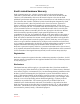
Exalt Communications, Inc. Exalt i-Series Installation and Management Guide Exalt Limited Hardware Warranty Exalt Communications, Inc. (“Exalt”) warrants solely to the original purchaser (“Purchaser”) that the EX-2.4i, EX-2.4i-16, the EX-5i, EX-5i-16 or the EX-4.
Exalt Communications, Inc. Exalt i-Series Installation and Management Guide RMA Procedures A return material authorization (RMA) is required prior to returning Product to Exalt for warranty or out-of-warranty repair/evaluation. As such, Purchaser must use the following procedure: 1. Contact Exalt and request an RMA number. Please be prepared to provide the serial number of the Product, the date of purchase, and a description of the failure that is as complete as possible. 2.
Exalt Communications, Inc. Exalt i-Series Installation and Management Guide IN NO EVENT SHALL EXALT’S AND ITS SUPPLIERS’ AGGREGATE LIABILITY EXCEED AN AMOUNT EQUAL TO THE PURCHASE PRICE OF THE PRODUCT PAID BY PURCHASER THAT IS THE SUBJECT OF A CLAIM. ANY CLAIM ARISING OUT OF OR RELATING TO THIS AGREEMENT MUST BE BROUGHT WITHIN ONE (1) YEAR AFTER THE OCCURRENCE OF THE EVENT GIVING RISE TO SUCH CLAIM. IN ADDITION, EXALT DISCLAIMS ALL LIABILITY OF ANY KIND OF EXALT’S SUPPLIERS.
Exalt Communications, Inc. Exalt i-Series Installation and Management Guide Table of Contents Legal Notice........................................................................................................................ 1 Open-Source License Information...................................................................................... 1 About this Document .......................................................................................................... 2 Revision History ................
Exalt Communications, Inc. Exalt i-Series Installation and Management Guide LEDs ......................................................................................................................... 32 System Installation and Initiation Process ........................................................................ 33 Record Keeping ............................................................................................................ 34 Installation...............................................
Exalt Communications, Inc. Exalt i-Series Installation and Management Guide Quick-Start.................................................................................................................... 57 Navigating the GUI....................................................................................................... 58 Summary Status Section ........................................................................................... 59 Navigation Panel.............................................
Exalt Communications, Inc. Exalt i-Series Installation and Management Guide Insufficient Link Margin............................................................................................... 95 Moisture in the Transmission System........................................................................... 95 Specifications.................................................................................................................... 96 Physical Specifications ........................................
Exalt Communications, Inc. Exalt i-Series Installation and Management Guide Federal Communications Commission (FCC), United States .................................... 127 United States Compliance............................................................................................... 128 Industry Canada (IC), Canada..................................................................................... 129 Antennas Supported in Canada.....................................................................
Exalt Communications, Inc. Exalt i-Series Installation and Management Guide Figure 7 GPS as primary sync source using AUTO SYNC ........................................ 31 Figure 8 Synchronized GPS sources using AUTO SYNC.......................................... 31 Figure 9 Radio installation tasks ................................................................................. 33 Figure 10 Front flush mount configuration ...................................................................
Exalt Communications, Inc. Exalt i-Series Installation and Management Guide Figure 39 Reboot page .................................................................................................. 88 Figure 40 Manual page.................................................................................................. 89 Figure 41 Basic back-to-back bench test configuration .............................................. 105 Figure 42 DC coupler interconnection .......................................
Exalt Communications, Inc. Exalt i-Series Installation and Management Guide Introduction Exalt Communications, Inc. thanks you for your purchase. Our goal is to build the highest quality, highest reliability digital microwave radio products. This commitment to quality and reliability extends to our employees and partners alike. We appreciate any comments on how we can improve our products, as well as your sales and Customer Care experience.
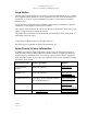
Exalt Communications, Inc. Exalt i-Series Installation and Management Guide Figure 1 EX-2.4i Digital Microwave Radio The i-Series radios connect voice and/or digital data from one location to another, obviating the need for copper or fiber connectivity, or enhancing existing connectivity by providing a redundancy solution, a primary solution, and/or additional capacity. The following models of radios are covered in this manual: • EX-2.
Exalt Communications, Inc. Exalt i-Series Installation and Management Guide Note: This manual uses terminology to distinguish the characteristics of specific radio models. The term standard refers to the EX-2.4i, EX-4.9i and EX-5i models. The term -16 refers to the EX-2.4i-16 and EX-5i-16 models. When no specific mention is made or the term i-Series is used, this refers to all models.
Exalt Communications, Inc. Exalt i-Series Installation and Management Guide The EX-4.9i utilizes frequencies in the 4940-4990MHz range, and is typically a licensed band reserved for use by Public Safety agencies and applications. This band is not generally available outside of North America. In almost all cases, either for license-exempt or other designation, the product itself must be authorized for use in your country.
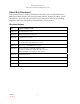
Exalt Communications, Inc. Exalt i-Series Installation and Management Guide ANTENNA RF LIGHTNING ARRESTOR (GROUNDED) RADIO CABINET GROUNDED POWER/DATA/INTERFACES LIGHTNING ARRESTOR(S) POWER/DATA/INTERFACES STRUCTURE PENETRATION POWER/DATA/INTERFACES Figure 3 Enclosure mount interconnection For highest performance and reliability, it is advised to minimize the length of RF cable and associated transmission system losses between the antenna and the radio’s antenna port.
Exalt Communications, Inc.
Exalt Communications, Inc. Exalt i-Series Installation and Management Guide Pre-installation Tasks This section describes the steps necessary to prepare a site for the installation of the Exalt Digital Microwave Radio. Link Engineering and Site Planning Design all terrestrial wireless links prior to purchase and installation.
Exalt Communications, Inc. Exalt i-Series Installation and Management Guide • Impact on throughput and latency relative to link distance, occupied bandwidth, and TDD frame size setting, and the planned implementation of these parameters Familiarization with i-Series Radios The i-Series radios utilize time division duplex (TDD) radio transmission.
Exalt Communications, Inc. Exalt i-Series Installation and Management Guide Shipping Box Contents Unless purchased as a spare terminal, the radios are shipped as a complete hop (that is, a radio link pair consisting of two terminals). An outer box has labeling that indicates the contents of the box, with the part number and serial number details for both radio terminals.
Exalt Communications, Inc. Exalt i-Series Installation and Management Guide Back-to-Back Bench Test and Configuration Every Exalt digital microwave radio goes through extensive quality testing and performance evaluation over the full operating temperature range prior to shipment. However, before installation, it is strongly advised to perform several tests and tasks that are much more difficult to perform once the radio link endpoints are distant from one another.
Exalt Communications, Inc. Exalt i-Series Installation and Management Guide Detailed performance measurements are usually not required for pre-installation, but can be easily performed at this stage and may be helpful for later troubleshooting efforts or for internal records.
Exalt Communications, Inc. Exalt i-Series Installation and Management Guide • Number of supported T1/E1 channels • Ethernet throughput • System latency (delay) Use the ExaltCalc calculator to determine optimum settings for the above parameters to meet the needs of your application.
Exalt Communications, Inc. Exalt i-Series Installation and Management Guide collocated radios may be transmitting and receiving at the same time, incurring near-end interference. Note: It is not always necessary to synchronize collocated radios. If antennas are substantially separated or blocked from one another and/or frequency separation tuning is used, the opportunity for near-end interference can be eliminated. Note: Internal and/or GPS sync features are not released for all models as of printing.
Exalt Communications, Inc. Exalt i-Series Installation and Management Guide Standard models: If radio configuration is unknown, and you do not have access to a computer and must install the radios immediately, the temporary hardware configuration key can help to establish a link or perform back-to-back bench testing, by helping to configure one of the radio terminals to Radio A.
Exalt Communications, Inc. Exalt i-Series Installation and Management Guide common clock system, ensuring that all radios simultaneously transmit and receive, and thus eliminating near-field interference issues and related radio system coupling. Note: The synchronization function is not currently available on all Exalt radio models. A firmware upgrade may be required for models without sync if sync is desired. Contact your Exalt representative for details.
Exalt Communications, Inc. Exalt i-Series Installation and Management Guide redundancy if the primary sync source radio (A) loses power or experiences any other failure.
Exalt Communications, Inc. Exalt i-Series Installation and Management Guide • Bandwidth – It is desirable, but not always necessary, to match the bandwidth for all collocated links. For complex networks, an Exalt engineer should review multi-link networks before deployment as several factors can optimize the network for desired performance. External Synchronization Use an external GPS source as an alternative to the internal synchronization source for system synchronization.
Exalt Communications, Inc. Exalt i-Series Installation and Management Guide such as GPS. The timing source to the Exalt radios can be adjusted to match the other radio system timing source mechanism. Offset timing can also optimize timing intervals for repeaters and backbones. As the distance of each link results in a unique factor for speed-of-light transmission of the radio signal, a subsequent radio can be delayed in timing so that the overall synchronization of radios is precisely maintained.
Exalt Communications, Inc. Exalt i-Series Installation and Management Guide System Installation and Initiation Process The tasks required for radio installation and initiation are outlined in the following figure.
Exalt Communications, Inc. Exalt i-Series Installation and Management Guide Record Keeping After installation, record the following items for ongoing maintenance and future troubleshooting. Keep a record for each end of the radio link and store a copy of these records at the radio location, at the opposite end radio location, and a central record storage location.
Exalt Communications, Inc. Exalt i-Series Installation and Management Guide Installation This section presents all tasks required to install the Exalt Digital Microwave Radio. Mechanical Configuration and Mounting The i-Series radios are one-piece radio designs intended for deployment in a telecom equipment rack indoors or in an appropriate environmental enclosure.
Exalt Communications, Inc.
Exalt Communications, Inc. Exalt i-Series Installation and Management Guide Table or Rack Shelf Mounting the System Affix rubber feet or adhesive-backed non-slip pads (not included) near the corners of the unit along the bottom panel when mounting on a table or a rack shelf. These pads help keep the radio stable on a wooden or metal surface. Caution: In many areas, it is necessary to strap the equipment to a table or rack shelf if mounting in this manner.
Exalt Communications, Inc. Exalt i-Series Installation and Management Guide Figure 15 Primary front panel connectors (standard models) Table 2 Connectors Label Type Gender Function Antenna N F Transmission line connection to GPS antenna. T1/E1 (1–4 or 1–16) RJ-48C F Primary ports for User T1 or E1 circuits to traverse link. ETHERNET RJ-45 F Primary ports for user Ethernet and/or management data (10BaseT or 100BaseT) to traverse link.
Exalt Communications, Inc. Exalt i-Series Installation and Management Guide LED Indicators Table 3 provides details of the LED indicators on all models.
Exalt Communications, Inc.
Exalt Communications, Inc. Exalt i-Series Installation and Management Guide RMT (Remote) Button The RMT button is the only external control on the radios. This button allows easy and quick evaluation of the status of the remote-end radio. Press and hold the button and, while held, all local-end status LEDs (LINK, STATUS, Radio A) represent the status of the LEDs on the remote-end radio. In addition, the RSL voltage represents the remoteend voltage.
Exalt Communications, Inc. Exalt i-Series Installation and Management Guide • Connect a fixed (or a series of fixed) 50-Ohm attenuator(s) to the RF connector, either directly or at the end of an RF transmission line. The attenuator must be at least 30dB as specified at the operating frequency (~2400 MHz for the EX-2.4i; ~4950 MHz for the EX-4.9i, ~5700 MHz for the EX-5i), and rated for a minimum of 1W input power.
Exalt Communications, Inc. Exalt i-Series Installation and Management Guide kind of signal interface, the opportunity for damage to the device, loss of communications and property is significant. In some cases, there can also be a risk to human life by not protecting against lightning entering a building through wiring or improper grounding.
Exalt Communications, Inc. Exalt i-Series Installation and Management Guide Warning: Consult a qualified electrician if uncertain about how to properly ground the system and connect power. Figure 16 DC connector Once the wires are connected to the mating connector, do not connect to the radio. First test the DC connection to the connector from the DC supply. Engage power on the DC supply, and use a volt meter to verify proper voltage level and polarity.
Exalt Communications, Inc. Exalt i-Series Installation and Management Guide 3. Hold the RMT button on the front panel while applying power. Continue to hold the RMT button through the entire boot cycle (approximately 45 seconds). The front-panel LEDs toggle during the boot cycle. 4. Release the RMT button when LED behavior stabilizes.
Exalt Communications, Inc. Exalt i-Series Installation and Management Guide Follow the antenna manufacturer’s instructions for mechanical mounting of the antenna. Ensure that there is enough room around the antenna for alignment activities (moving the antenna in vertical and horizontal arcs), and for the RF transmission line to connect to the antenna connector unobstructed and within the specified bend radius requirements of the transmission line.
Exalt Communications, Inc. Exalt i-Series Installation and Management Guide Manufacturer Type Description Loss at 2.4GHz Loss at 4.9GHz Loss at 5.3GHz Loss at 5.8GHz Andrew LDF4.5-50 5/8-inch solid shield 2.5dB/100ft. 4.3dB/100ft. 4.4dB/100ft. 4.7dB/100ft. Times LMR-600 1/2-inch braided shield 4.3dB/100ft. 6.8dB/100ft. 6.9dB/100ft. 7.3dB/100ft. Times LMR-900 5/8-inch braided shield 2.9dB/100ft. 4.5dB/100ft. 4.6dB/100ft. 4.9dB/100ft. RFS LCF12-50J 1/2-inch solid shield 3.
Exalt Communications, Inc. Exalt i-Series Installation and Management Guide The manufacturers of transmission line typically offer instruction and certification for transmission line termination, and may also provide videos illustrating the process. There is no amount of extra care, education, precision, and effort that can be overstated for this process. Once the transmission line is connected to the antenna, traverse the exact route provided by the site planner.
Exalt Communications, Inc. Exalt i-Series Installation and Management Guide The following lightning arrestors are examples of proper devices for Exalt Digital Microwave Radios: • Polyphaser AL-LSXM • Andrew BB-BNFNFE-26 Mount and ground the RF lightning arrestor in accordance to the manufacturer’s recommendations. Place it as close as possible to the egress point where the next piece of transmission line enters the building or enclosure.
Exalt Communications, Inc. Exalt i-Series Installation and Management Guide Antenna Alignment Antennas must be installed at both ends of the planned link to commence precision alignment. Refer to the Exalt white paper, Antenna Alignment. Antennas are typically aligned using the radio hardware for precise alignment. However, there are many very useful tools available to aid in this process, inclusive of devices specifically designed for the purpose of aligning antennas.
Exalt Communications, Inc. Exalt i-Series Installation and Management Guide Note: Due to the resistance of the cable, the RSL readings might be impacted. Use the thickest wiring possible. Test the impact of the voltage reading due to the wiring by comparing a direct measurement at the RSL test point as opposed to the end of the wiring. • RF/DC coupler Install a temporary DC coupling device at the radio antenna port and at the antenna connector.
Exalt Communications, Inc. Exalt i-Series Installation and Management Guide Configuration and Management This section describes the command line interface (CLI) and Exalt graphical user interface (GUI). Command Line Interface (CLI) Exalt Digital Microwave Radios provide a CLI to set key parameters on the system. Use the Console port for serial devices, or use the Ethernet MAIN or AUX ports for a Telnet session over a network connection.
Exalt Communications, Inc. Exalt i-Series Installation and Management Guide CLI Screens and Menus Use CLI or Telnet when prompted, and enter the administration level login and password. The default administration login is admin and password is password (or admin for early firmware releases). It is recommended that the default administration password be reset by performing a radio reset (see Reset to Critical Factory Settings on page 44). The serial port CLI and Telnet CLI are identical.
Exalt Communications, Inc. Exalt i-Series Installation and Management Guide 3. Status ¶ Alarm summary ¶ Radio alarm ¶ Radio status ¶ Radio performance ¶ Radio performance reset (admin only) 4. Exit Exalt Graphical User Interface (GUI) The Exalt GUI is the primary user interface for configuring and troubleshooting the radio and radio system. A computer or hand-held device with a conventional HTML browser and Ethernet port is required. Microsoft Internet Explorer is the preferred browser.
Exalt Communications, Inc. Exalt i-Series Installation and Management Guide 2. Use the front panel DIP switch, as discussed in DIP Switch Configuration (-16 Models Only) on page 28. 3. Connect to the GUI and change the configuration, as discussed in this section (preferred).
Exalt Communications, Inc. Exalt i-Series Installation and Management Guide The following window displays after pressing the Enter key or clicking the Go button in the browser window.
Exalt Communications, Inc. Exalt i-Series Installation and Management Guide Figure 20 Radio Information page Quick-Start To establish a link on the bench, apply the following basic configurations to the radio terminal. Use the steps in the Quick Start Guide included with the radio. A summary of the items that need to be configured are: • Radio IP address for each end.
Exalt Communications, Inc. Exalt i-Series Installation and Management Guide • Set one radio as Radio A. ¶ The radio selected as Radio A must be configured. ¶ Radio A/B selection is the Endpoint Identifier parameter on the System Configuration page. ¶ Even though both radios are set as Radio B by default, confirm this configuration on the radio intended to be Radio B.
Exalt Communications, Inc. Exalt i-Series Installation and Management Guide Summary Status Navigation Panel Main Window Figure 21 Exalt GUI window description Summary Status Section This section of the Exalt GUI provides a review of the system status. Figure 22 Minimized browser windows for summary status of multiple radios In the screens in Figure 22, the top bar illustrates the alarm condition of the link.
Exalt Communications, Inc. Exalt i-Series Installation and Management Guide Note: The ‘local’ radio might be the near-end or the far-end radio, depending on the management interface connection. The terms local and remote refer to the orientation of the radio terminals relative to the IP address you are managing.
Exalt Communications, Inc. Exalt i-Series Installation and Management Guide Radio Information Page This page provides general information about the local radio terminal. This information is helpful for troubleshooting and for record keeping.
Exalt Communications, Inc. Exalt i-Series Installation and Management Guide Administration Settings Page This page allows contains general parameters for the radio system. The Current Value column lists entries actual settings. Desired changes are entered in the New Value column. After all desired changes are entered, click the Update button to accept and enable changes. Figure 24 Administration Settings Page Most entries on this page are self-explanatory.
Exalt Communications, Inc. Exalt i-Series Installation and Management Guide sabotage by a party with the same radio model. Each link should have a unique security key. If using the same security key for every link in the network, the radio could link to any other radio with the same security key. This is problematic in multiradio networks. ¶ Note that the security key must be exactly 12 characters. Any printable ASCII character can be used. The link security key is case sensitive.
Exalt Communications, Inc. Exalt i-Series Installation and Management Guide System Configuration Page This page contains several critical system parameters. Figure 25 System Configuration Page Most entries on this page are self-explanatory. The following lists unique or important parameters: • Set the Radio Transmit Power parameter to the designed level.
Exalt Communications, Inc. Exalt i-Series Installation and Management Guide ¶ Do not adjust the Radio Transmit Power parameter to a value higher than is legally allowed. ¶ Do not adjust the Radio Transmit Power parameter lower than the link budget and fade margin can afford. The link may be lost and unrecoverable through GUI control. If the link is lost due to reduction of Radio Transmit Power, travel to the radio location(s) may be required to reset the value.
Exalt Communications, Inc. Exalt i-Series Installation and Management Guide Note: Changing Mode will temporarily interrupt traffic. The Mode setting must match at each end. Adjust the far-end radio first, and then the near-end radio. Changing Mode changes the radio’s threshold, carrier-to-interference ratio, and also may have impact on the Radio Transmit Power.
Exalt Communications, Inc. Exalt i-Series Installation and Management Guide • Set the Link Distance parameter to the range that is equal to or greater than the actual link distance. The value of this setting is determined in the design/engineering stage. Note: Changing Link Distance parameter will temporarily interrupt traffic. The Link Distance setting must match at each end and must not be less than the actual link distance. Adjust the far-end radio first, and then the near-end radio.
Exalt Communications, Inc. Exalt i-Series Installation and Management Guide Ethernet Interface Configuration Page This page allows the administrator to set the muting, alarm, and duplex settings of both the ETHERNET MAIN and AUX connections. It also allows determination of the management information for in-band (carried over the air and available from both the MAIN and AUX connectors on either end of the link) or out-of-band (not carried over the air and only available from the local AUX connector).
Exalt Communications, Inc. Exalt i-Series Installation and Management Guide T1/E1 Configuration Pages These pages allow the administrator to selectively enable or disable the T1 or E1 circuits, one at a time. For enabled T1/E1 circuits, additional configuration, including loopback functions, are available. Disable the unused T1 or E1 so that the alarms are turned off and more throughput is allocated to the Ethernet interface.
Exalt Communications, Inc. Exalt i-Series Installation and Management Guide Figure 27 T1 Interface Configuration page (standard models) E1 Interface Configuration Page This page allows the administrator to enable/disable each individual E1 channel. The AIS can also be enabled and disabled for each input.
Exalt Communications, Inc. Exalt i-Series Installation and Management Guide Figure 28 E1 Interface Configuration page (standard models) T1/E1 Loopback Loopback is provided for any enabled T1 or E1 port. As shown in Figure 29 and Figure 30, the choices are: • No Loopback (default) • External (local) • External (remote) • Internal Note: Only one Internal loopback can be enabled at any time.
Exalt Communications, Inc. Exalt i-Series Installation and Management Guide LOCAL IN REMOTE IN OUT OUT Figure 29 IN External (remote) loopback LOCAL REMOTE OUT Figure 30 IN OUT External (local) loopback When a local T1/E1 port is configured for External (remote) loopback, it is the same as configuring the remote radio for External (local) loopback.
Exalt Communications, Inc. Exalt i-Series Installation and Management Guide File Transfer Page This page allows the administrator to upload and download files to and from the radio. Two types of files can be uploaded: configuration and radio firmware. When uploading Configuration Files, current configuration parameters are immediately overwritten, and the unit automatically reboots. When uploading radio firmware files, the file is placed into reserve memory space.
Exalt Communications, Inc. Exalt i-Series Installation and Management Guide Use the following steps to download a file 1. Select the type of file to download (configuration or radio firmware) 2. Click the DOWNLOAD button and wait for the radio to prepare the file for download. For the MIB file download, a second page/link appears (Figure 33). 3. Right-click the link on the page to download the file to a desired location.
Exalt Communications, Inc.
Exalt Communications, Inc. Exalt i-Series Installation and Management Guide File Activation Page Use this page to move stored or uploaded files for use on the radio. The page indicates which file is currently in use, and which file is available for use. Click the Swap button to place the file in the Alternative File column into the active state and move the file in the Current File column to the Alternative File column.
Exalt Communications, Inc. Exalt i-Series Installation and Management Guide Simple Network Management Protocol (SNMP) Configuration Use SNMP to manage networked devices and execute the following functions: • GET: Obtain information from the device, such as a configuration setting or parameter. • SET: Change a configuration setting on the device. • TRAP: The device proactively informs the management station of a change of state, usually used for critical alarms or warnings.
Exalt Communications, Inc. Exalt i-Series Installation and Management Guide Alarms Page This page provides an easy-to-read summary of the alarm status of both local and remote radios. The colors on this page reflect the color of the alarms displayed on the radio front panel. However, additional detail displays on this page to aid in quick assessment of issues and status. Figure 35 Alarms page (standard models) See Table 3 for more information on the front panel LEDs.
Exalt Communications, Inc. Exalt i-Series Installation and Management Guide • The Temperature alarm monitors the internal temperature of the unit based on specific points inside the radio chassis. It is normal for the internal temperature to be above the ambient temperature, so the temperature reading may be higher than the highest specified ambient temperature.
Exalt Communications, Inc. Exalt i-Series Installation and Management Guide Performance Page This page provides statistical information about the performance of the system in relation to the integrity of the user data and the RF link. Figure 36 • Performance page The Current BER field indicates the current bit error rate of the link. If the link is operating perfectly, this should indicate zero. Generally, the link should remain at a BER less than 1x10⁻⁶ (1 bit out of every million bits errored).
Exalt Communications, Inc. Exalt i-Series Installation and Management Guide • Current RSL is the measurement of the received signal level at the radio antenna port. This is the measured level of the RF signal coming from the opposite end of the radio link. The link was engineered to a specific RSL by the link design engineer, and this RSL should be obtained during installation and remain relatively stable during the operation of the link.
Exalt Communications, Inc. Exalt i-Series Installation and Management Guide • Maximum RSL indicates the best (highest) RSL that occurred since the last counter reset. This indicates the best performance of the radio link, which is normally equal to the installed value, and is usually the designed value. • Time Since Reset indicates the amount of time passed since the last counter reset.
Exalt Communications, Inc. Exalt i-Series Installation and Management Guide Event Log Page Use this page to review a list of the events logged by the radio.
Exalt Communications, Inc. Exalt i-Series Installation and Management Guide Every event is tagged with the time that the event occurred, and a severity and type. The event log also allows filtering to limit the view of the log to the lowest level of desired information. For example, a filter level of Minor displays Minor, Major, and Critical severity events. The log contains the last 200 events. Events are deleted on a FIFO basis, erasing the oldest entries to make room for the newest entries.
Exalt Communications, Inc. Exalt i-Series Installation and Management Guide Diagnostic Charts Page Use this page as an aid in troubleshooting. This page illustrates the historical (and current) performance for three parameters: RSL, Radio Temperature, and BER. The horizontal scale illustrates 120 points of time measurement and is synchronized on all three graphs. The scale displays in minutes, hours, or days from the last two hours (120 minutes), five days (120 hours), or four months (120 days).
Exalt Communications, Inc. Exalt i-Series Installation and Management Guide Figure 38 Diagnostic Charts page Use the cursor to point to any spot on any of the three charts, and all three charts illustrate the measurements taken for that time interval in the upper-left corner of each chart. The time interval is indicated by T=(value). This is followed by the value of the measurement, listing the highest value, lowest value and average value measured over that time interval.
Exalt Communications, Inc. Exalt i-Series Installation and Management Guide Changes in RSL often have an impact on BER, and this can be confirmed by looking for synchronized events. When BER events occur without corresponding changes in RSL, this normally indicates interference, atmospheric changes, transmission system issues (such as problems with cables, connectors or antennas), or possibly radio hardware problems.
Exalt Communications, Inc. Exalt i-Series Installation and Management Guide Reboot Page Use this page to reboot the radio. The function may never be required, but can be used in emergencies. All configurations that require a reboot automatically reboot on administrator confirmation.
Exalt Communications, Inc. Exalt i-Series Installation and Management Guide Manual Page The manual (this document or the version that matches the installed firmware) is available within the GUI. Adobe Acrobat Reader 5.5 or higher is required (go to www.adobe.com to download Acrobat Reader). Click the Manual link and the manual displays within the browser window. Once the manual displays, click the save button on the PDF toolbar to download the manual locally.
Exalt Communications, Inc. Exalt i-Series Installation and Management Guide Troubleshooting This section provides information regarding troubleshooting of common issues and alarms on these radios. Exalt Digital Microwave Radio systems are designed by Exalt’s expert engineers with extensive experience through multiple generations of microwave radio design. These new-generation systems contain extensive diagnostic tools, alarm indications, and troubleshooting aids.
Exalt Communications, Inc. Exalt i-Series Installation and Management Guide If the radio link has been operating without issues and is exhibiting new poor performance behavior or becomes completely inoperative, the troubleshooting process should pay close attention to any conditions that may have changed between the time when the system was working without issue and the time when the issues started.
Exalt Communications, Inc. Exalt i-Series Installation and Management Guide Most importantly, monitoring radio system RSL over time indicates the performance of the radio system. Address any long-term drop in RSL and erratic or unsteady RSL. Some RSL changes are expected and weather patterns and the related multipath can cause dramatic RSL changes resulting in system outage. However, that outage should not occur at a significantly greater rate than the designed long-term performance.
Exalt Communications, Inc. Exalt i-Series Installation and Management Guide Use a reflectometer or meter that can read VSWR at the operating frequency to identify poor terminations as well as poor antenna feeds.
Exalt Communications, Inc. Exalt i-Series Installation and Management Guide by the radio indicates the level of interference seen by the radio. It is possible that interference levels below that which can be measured still have an impact on the radio system – especially if the radio system has low fade margin or is using a high order modulation. The EX-2.4i and EX-5i families provide considerable flexibility to tune to different frequencies across the bands within which they operate.
Exalt Communications, Inc. Exalt i-Series Installation and Management Guide Improper Grounding In addition to being a potential human safety issue, improper system grounding is a somewhat common condition that can cause continuous bit errors or bit errors when metal objects come in contact with the radio, transmission system, or racking system. If touching the radio causes errors, grounding is the cause.
Exalt Communications, Inc. Exalt i-Series Installation and Management Guide Specifications This section presents specifications for the i-Series of Digital Microwave Radios. Physical Specifications Physical Configuration Single-piece Indoor Unit (IDU) Dimensions (HxWxD), (std models) 1RU: 1.75" x 17" x 14"/ 4.5 x 43.2 x 35.6 cm Dimensions (HxWxD), (-16 models) 1.5RU: 2.63" x 17" x 14"/ 6.7 x 43.2 x 35.6 cm Weight (std models) 11.3 lbs/5.1 kg Weight (-16 models) 12 lbs/5.
Exalt Communications, Inc. Exalt i-Series Installation and Management Guide *Not all Bandwidth and Mode combinations are available on all radio models, and some may require specific software license keys, which may be purchased from an authorized Exalt representative. EX-2.4i System Specifications Frequency Band 2400 to 2483.5MHz Tunable Range 2406 to 2468MHz Output Power (at full power) +27dBm (0.5W), Mode 1 +24dBm (0.
Exalt Communications, Inc. Exalt i-Series Installation and Management Guide EX-4.
Exalt Communications, Inc. Exalt i-Series Installation and Management Guide EX-5i System Specifications, 5.3 GHz Band Frequency Band 5250 to 5350 MHz Tunable Range 5260 to 5332 MHz Output Power (at full power) +13dBm (0.
Exalt Communications, Inc. Exalt i-Series Installation and Management Guide EX-5i System Specifications, 5.4 GHz Band Frequency Band 5470 to 5725 MHz Tunable Range 5488 to 5715 MHz Output Power (at full power) +13dBm (0.
Exalt Communications, Inc. Exalt i-Series Installation and Management Guide EX-5i System Specifications, 5.8 GHz Band Frequency Band 5725 to 5850 MHz Tunable Range 5731 to 5844 MHz Output Power (at full power) +24dBm (0.25W), Mode 1 +21dBm (0.
Exalt Communications, Inc. Exalt i-Series Installation and Management Guide Interfaces RF Connector N-type female Impedance 50 Ohms T1/E1 (x4 or x16) Connector RJ-45 (RJ48C), female T1 Impedance 100 Ohms, balanced T1 Line Codes AMI, B8ZS, selectable T1 LBO Settings (in ft.) 0-133, 133-266, 266-399, 399-533, 533-655 T1 Clocking Speed 1.544 Mbps T1 Compliance ANSI T1.102-1987; ITU-T; G.823; GR-49T-CORE E1 Impedance 120 Ohms, balanced E1 Line Codes HDB3 E1 Clocking Speed 2.
Exalt Communications, Inc. Exalt i-Series Installation and Management Guide Sync (In and Out) Connector RJ45, female Signal 1 pps (GPS) Power Connector 6-pin barrier strip Input Voltage (standard models) 20–60VDC Consumption (standard models) <38.5W (0.8A @ 48V; 1.6A @ 24V) Input Voltage (-16 models) 20–60VDC Consumption (-16 models) < 45W (0.9A @ 48V; 1.
Exalt Communications, Inc. Exalt i-Series Installation and Management Guide Back-to-back Bench Testing Use back-to-back bench testing to test the radio before installation, pre-configure the radio and connected equipment before installation, or in the troubleshooting process to identify if the radio hardware is the source of a system issue. It is a critical process, and often required or highly desirable for any installation or troubleshooting exercise.
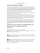
Exalt Communications, Inc. Exalt i-Series Installation and Management Guide RF PORTS RADIO B CONSOLE PORT ATTENUATION (60-90DB) RADIO A SERIAL PORT POWER (CONNECT LAST) POWER (CONNECT LAST) Figure 41 COMPUTER Basic back-to-back bench test configuration After connecting and powering on, observe the front panel LEDs to verify that the LINK and STATUS LEDs are green. If so, the radios are communicating and all radio-related alarm conditions are normal.
Exalt Communications, Inc. Exalt i-Series Installation and Management Guide Use the volt meter to measure RSL in both directions. The RSL measured value should match the appropriate value according to the inserted attenuation, such as: RSL = RF Output Power – cabling losses – total attenuation Verify output power by adjusting output power using the Exalt GUI (in administration mode) and evaluate the corresponding change to the RSL measurement.
Exalt Communications, Inc. Exalt i-Series Installation and Management Guide DC Coupler for Antenna Alignment One challenge associated with an all-indoor radio construction is the alignment of the antennas. It can sometimes be challenging to place the radio near the antenna alignment personnel, and can also be challenging to run a separate set of wires for the voltmeter to be in view of the alignment personnel.
Exalt Communications, Inc. Exalt i-Series Installation and Management Guide COUPLER (DC SIDE TOWARD RADIO) PRIMARY TRANSMISSION LINE ANTENNA DVM JUMPER CABLE OR ADAPTER (IN PLACE OF LIGHTNING ARRESTOR) STRUCTURE PENETRATION SECONDARY TRANSMISSION LINE RADIO COUPLER (DC SIDE TOWARD ANTENNA) TO RSL PORT Figure 42 POWER/DATA/INTERFACES DC coupler interconnection Note: After completing antenna alignment, remove the DC couplers and associated wiring at both radio and antenna ends.
Exalt Communications, Inc. Exalt i-Series Installation and Management Guide Interface Connections This section provides the pin number assignment and wiring information for the connectors on the i-Series radios. All connectors are shown as viewed from the radio front panel. T1/E1 Connections There are two orientations of T1/E1 connections. Depending on model, some channels have the securing tab towards the top of the connector, and others have the securing tab towards the bottom of the connector.
Exalt Communications, Inc. Exalt i-Series Installation and Management Guide Ethernet Connections There are two orientations of Ethernet connections. AUX has the securing tab towards the top of the connector while MAIN has the securing tab towards the bottom of the connector. Figure 44 illustrates the pin orientation and functionality of these connectors.
Exalt Communications, Inc. Exalt i-Series Installation and Management Guide Sync Connections There are two sync connectors: Sync In and Sync Out. The Sync In connector is normally connected to a (custom) GPS antenna system, or to the Sync Out connector of a collocated radio.
Exalt Communications, Inc. Exalt i-Series Installation and Management Guide Alarm Connector The Alarm connector provides two alarm outputs that can be connected to external alarm collection equipment. The connector also allows connection of up to two external alarm sources, where the radio will report the status of these connections through the radio network management.
Exalt Communications, Inc. Exalt i-Series Installation and Management Guide Console Connector The Console connector provides a serial interface for the Command Line Interface (CLI) functions. Typically, a straight-through serial cable is used between a computer’s serial port and the Console connector.
Exalt Communications, Inc. Exalt i-Series Installation and Management Guide DIP Switch Settings (-16 Models Only) The ‘-16’ models incorporate a front panel DIP switch. Use the DIP switch for emergency configuration or restoration for installations where there is no computer available for complete radio configuration. Only use the DIP switch for temporary purposes, for the purpose of a bench test or antenna alignment.
Exalt Communications, Inc. Exalt i-Series Installation and Management Guide Table 7 provides the standard factory defaults for the ‘-16’ models. Table 7 Standard Factory Defaults (-16 Models) Parameter EX-2.
Exalt Communications, Inc. Exalt i-Series Installation and Management Guide Change TDM interfaces to E1 1x1xxxxx Choose the desired reset function using position 4. Reset both radios with position 3 up to configure E1 at each end. One radio must be Radio B, and the other Radio A (using position 2). Configure for ideal antenna alignment configuration 1xx1xxxx Reset the radio with position 4 up to configure for the best setting to optimize antenna alignment.
Exalt Communications, Inc. Exalt i-Series Installation and Management Guide Copyright Notices This section present copyright notices for third-party software licensed to Exalt Communications, Inc. Net-SNMP The following copyright notice applies to the open-source licensing agreement for Net-SNMP.
Exalt Communications, Inc. Exalt i-Series Installation and Management Guide Network Associates Technology, Inc. Copyright (c) 2001-2003, Networks Associates Technology, Inc All rights reserved. Redistribution and use in source and binary forms, with or without modification, are permitted provided that the following conditions are met: * Redistributions of source code must retain the above copyright notice, this list of conditions and the following disclaimer.
Exalt Communications, Inc. Exalt i-Series Installation and Management Guide TO, THE IMPLIED WARRANTIES OF MERCHANTABILITY AND FITNESS FOR A PARTICULAR PURPOSE ARE DISCLAIMED.
Exalt Communications, Inc. Exalt i-Series Installation and Management Guide Sparta, Inc. Copyright (c) 2003-2005, Sparta, Inc All rights reserved. Redistribution and use in source and binary forms, with or without modification, are permitted provided that the following conditions are met: * Redistributions of source code must retain the above copyright notice, this list of conditions and the following disclaimer.
Exalt Communications, Inc. Exalt i-Series Installation and Management Guide THIS SOFTWARE IS PROVIDED BY THE COPYRIGHT HOLDERS AND CONTRIBUTORS ''AS IS'' AND ANY EXPRESS OR IMPLIED WARRANTIES, INCLUDING, BUT NOT LIMITED TO, THE IMPLIED WARRANTIES OF MERCHANTABILITY AND FITNESS FOR A PARTICULAR PURPOSE ARE DISCLAIMED.
Exalt Communications, Inc. Exalt i-Series Installation and Management Guide Appendix A - Regulatory Compliance As of this printing, Exalt Communications, Inc. has approvals for the products that are covered by this manual as indicated in Table 11. If your application or country is not listed, please check with your Sales Representative for the current status. Table 9 Product Approvals Country EX-2.4i series EX-4.9i series EX-5i series, 5.3 GHz EX-5i series, 5.4 GHz EX-5i series, 5.
Exalt Communications, Inc. Exalt i-Series Installation and Management Guide Romania 8 8 8 8 Slovak Republic 8 8 8 8 Slovenia 8 Sweden 8 8 8 8 Switzerland 8 8 8 8 Turkey 8 8 8 8 United States 8 8 8 8 8 8 General Regulatory Notices Dynamic Frequency Selection Dynamic Frequency Selection (DFS) may be required by regional legislation in some frequency bands in order to avoid causing interference to radar systems.
Exalt Communications, Inc. Exalt i-Series Installation and Management Guide Table 10 EX-2.4i supported antennas Manufacturer Model # Description Mid-band Gain (dBi) 3dB (Azimuth/Elevation) Beamwidth (degrees) Andrew 19T-2440-1 16-inch Solid Parabolic Dish 19 16/17 Andrew 21T-2441-1 24-inch Solid Parabolic Dish 21 10/11 Andrew 18T-2400-1 Semi-parabolic Grid 17 14/13 Andrew 26T-2400-1 Semi-parabolic Grid 23 7.5/10 Andrew P2F-23 2-foot Solid Parabolic Dish 21.6 12/13.
Exalt Communications, Inc. Exalt i-Series Installation and Management Guide Table 11 lists antennas supported by the EX-5i family of Digital Microwave Radios. Table 11 EX-5i supported antennas Manufacturer Model # Description Mid-band Gain dBi (mid-band) 3dB (Azimuth/Elevation) Beamwidth (degrees) Andrew P2F-52-N 2-foot Dish 29.4 5.4 Andrew P3F-52-N 3-foot Dish 33.4 3.8 Andrew P4F-52-NXA 4-foot Dish 34.9 3.0 Andrew P6F-52-NXA 6-foot Dish 37.6 1.
Exalt Communications, Inc. Exalt i-Series Installation and Management Guide Manufacturer Model # Description Mid-band Gain dBi (mid-band) 3dB (Azimuth/Elevation) Beamwidth (degrees) RFS SDF6-52A 6-foot HP Dish 37.4 2.1 RFS MA0528-19AN 7.5-inch Panel 19.0 18.0 RFS MA0528-23AN 1-foot Panel 23.0 9.0 RFS MA0528-28AN 2-foot Panel 28.0 4.
Exalt Communications, Inc. Exalt i-Series Installation and Management Guide Region 1 Specifics Region 1 is designated for USA and Canada installations. Note: The professional installer is responsible to ensure that RF output power is properly adjusted to not exceed the regulatory limit. 4.9 GHz Model The EX-4.9i is a licensed-band product operating within Part 90 of the FCC regulations and RSS-111 of Industry Canada. This band is specifically reserved for Public Safety applications and related agencies.
Exalt Communications, Inc. Exalt i-Series Installation and Management Guide Changes or modifications not expressly approved in writing by Exalt may void the user’s authority to operate this equipment. This device must be professionally installed. To comply with regulations, the output power of this device may need to be adjusted in accordance to the associated transmission system. See RF Output Power Setting on page 25 in this Appendix for details. The antenna associated with EX-2.
Exalt Communications, Inc. Exalt i-Series Installation and Management Guide – Directional flat panel: 28 dBi (~2'/61cm square) Industry Canada (IC), Canada This device complies with RSS-210 of Industry Canada. Operation is subject to the following two conditions: 3. this device may not cause interference, and 4. this device must accept any interference, including interference that may cause undesired operation of the device. Antennas Supported in Canada The EX-2.
Exalt Communications, Inc. Exalt i-Series Installation and Management Guide ¶ EX-2.4i models: – Parabolic dish: 30.3 dBi (6'/1.8m diameter) – Directional flat panel: 20.5 dBi (~2'/61cm square) ¶ EX-4.9i models: – Parabolic dish: 26 dBi (larger gains are allowed with Tx power reduction) – Directional flat panel: 26 dBi (larger gains are allowed with Tx power reduction) ¶ EX-5i models: – Parabolic dish: 37.9 dBi (6'/1.
Exalt Communications, Inc. Exalt i-Series Installation and Management Guide Industry Canada (IC), Canada on page 128. EX-2.4i EIRP for the USA and Canada For the EX-2.4i models, the maximum EIRP allowed is +52.2 dBm. The maximum conducted power of the radio is +27 dBm for Mode 1 and +24 dBm for Mode 2.
Exalt Communications, Inc. Exalt i-Series Installation and Management Guide EX-5i EIRP for the US and Canada 5250-5350 MHz Band For the EX-5i models within the 5250–5350 MHz band, the maximum transmit power is 30 dBm. The maximum output of the radio is +13 dBm.
Exalt Communications, Inc. Exalt i-Series Installation and Management Guide 5725-5850 MHz Band For the EX-5i models within the 5725–5850 MHz band, the maximum EIRP allowed is 61.9 dBm. The maximum output power of the radio is +24 dBm in Mode 1 and +21 dBm in Mode 2.
Exalt Communications, Inc. Exalt i-Series Installation and Management Guide Region 2 Specifics The countries that are covered by this region are: Austria, Belgium, Cyprus, Czech Republic, Denmark, Estonia, Finland, France, Germany, Great Britain, Greece, Hungary, Iceland, Ireland, Italy, Latvia, Liechtenstein, Lithuania, Luxembourg, Malta, Norway, Poland, Portugal, Slovak Republic, Slovenia, Spain, Sweden, Netherlands, Switzerland, and Turkey.
Exalt Communications, Inc. Exalt i-Series Installation and Management Guide Declaration of Conformity to the R&TTE Directive 1999/5/EC English: This equipment is in compliance with the essential requirements and other relevant provisions of Directive 1999/5/EC. Deutsch: Dieses Gerät entspricht den grundlegenden Anforderungen und den weiteren entsprecheneden Vorgaben der Richtlinie 1999/5/EU.
Exalt Communications, Inc. Exalt i-Series Installation and Management Guide The WEEE Directives are being implemented in each of the 28 EU and European Economic Area (EAA) countries through national legislation. This has resulted in considerable variation in the detailed requirements across the EU, many of which require presence in the EU.
Exalt Communications, Inc. Exalt i-Series Installation and Management Guide • Use only parabolic dish antennas or directional flat-panel antennas. No other types of antennas (omni-directional, yagi, and so on) are authorized. Parabolic dishes of either grid or solid type are allowed. Maximum mid-band gain of each type of antenna certified is: ¶ EX-2.4i models: – Parabolic dish: 30.3 dBi (6'/1.8m diameter) – Directional flat panel: 20.5 dBi (~2'/61cm square) ¶ EX-5i models: – Parabolic dish: 37.
Exalt Communications, Inc. Exalt i-Series Installation and Management Guide EX-2.4i EIRP by Country For the EX-2.4i models within the 2400-2483.5 MHz band, the maximum EIRP allowed is 20 dBm and the countries are summarized in Table 12. The maximum output power of the radio is +13 dBm.
Exalt Communications, Inc. Exalt i-Series Installation and Management Guide Table 12 Region 2 Country Specific Power Levels for EX2.
Exalt Communications, Inc. Exalt i-Series Installation and Management Guide EX-5i EIRP by Country Table 13 summarizes the maximum power by band and country for Exalt’s EX-5i series products. 5250–5350 MHz band For the EX-5i models within the 5250–5350 MHz band, the maximum transmit power is 23 dBm. The maximum output of the radio is +13 dBm.
Exalt Communications, Inc. Exalt i-Series Installation and Management Guide cables, connectors, lightning suppressors), in dB, as specified or measured between 5470 and 5725 MHz 5725-5850 MHz band For the EX-5i models, within the 5725-5850 MHz band, the maximum transmit power with respect to specific country EIRP regulations is determined based on the channel bandwidth. The EIRP power limit is 33 dBm for 10 MHz channels and 36 dBm for 20 MHz channels.
Exalt Communications, Inc. Exalt i-Series Installation and Management Guide Table 13 Region 2 Country Specific Power Levels for EX-5i Series Country Maximum EIRP Output Power, 5.3 GHz band Maximum EIRP Output Power, 5.4 GHz band Maximum EIRP Output Power, 5.
Exalt Communications, Inc.
Exalt Communications, Inc.
Exalt Communications, Inc. Exalt i-Series Installation and Management Guide Minimum RSL field, 81 Minimum RSL Timestamp field, 81 Mode parameter, 65 modes AUTO SYNC, 29 multi-link backbone, 30 multi-link network, 31 multipath, 92 multipath propagation, 93 muting, 68 radio mount enclosure, 18 connections, 19 indoor, 18 connections, 18 Radio Name parameter, 75 Radio Transmit Power parameter, 64 Reboot page, 88 received signal level (RSL).
Exalt Communications, Inc.
Exalt Communications, Inc. Exalt i-Series Installation and Management Guide © 2007 Exalt Communications Inc. 580 Division St.