OWNER’S OPERATION and MAINTENANCE MANUAL A Division of
Thank you for your selection of Pleasurecraft (PCM) Marine Power for your boating needs. We welcome you to Team PCM, which puts you in the company of tens of thousands of boaters who have relied on Pleasurecraft inboards as their power of choice for over 20 years. When you chose PCM, you selected the utmost in premium power for your boating application. Pleasurecraft is the world’s largest manufacturer of gasoline marine inboards, and the clear-cut leader in cutting edge technology.
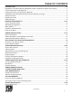
TABLE OF CONTENTS INTRODUCTION ..................................................................................................................... 3-5 Registration Information (Warranty Registration Card is located at the back of this manual) ....................... 3 3-Year Transferable Limited Warranty .............................................................................................. 4 California Emission Control Warranty Statement ............................................................
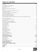
TABLE OF CONTENTS Checking Fluid Levels ........................................................................................................... 27-28 Lubrication .............................................................................................................................. 29 Electrical System Circuit Breaker(s) .............................................................................................. 30 Electrical System Fuses .........................................................
INTRODUCTION - 1 REGISTRATION INFORMATION (Warranty Registration Card is located at the back of this manual) Shortly after your purchase is registered with PCM, you will be mailed your Warranty Card and a Customer Survey. We appreciate your feedback and encourage you to fill out the survey after you have had a chance to run your boat for several weeks. We take this input very seriously, and have implemented many of the ideas our customers have given us through this survey.
INTRODUCTION - 1 3 Year Transferable Limited Warranty Pleasurecraft Marine Engine Co. (PCM) warrants its new products to be free from defects in material and workmanship under normal use and service conditions, to the first registered user, and all subsequent user who, in accordance with PCM’s warranty transfer policy, transfers any remaining portion of this warranty coverage within 30 days of any subsequent sale/purchases.
INTRODUCTION - 1 CALIFORNIA EMISSION CONTROL WARRANTY STATEMENT YOUR WARRANTY RIGHTS AND OBLIGATIONS The California Air Resources Board and Pleasurecraft Marine Engine Co. (hereinafter “Pleasurecraft”) are pleased to explain the emission control system warranty on your Model Years 2003-2008 inboard engine. In California, new inboard engines must be designed, built and equipped to meet the State’s stringent anti-smog standards.
INTRODUCTION - 1 PLEASURECRAFT MARINE ENGINE CO. MODEL YEARS 2003-2008 GENERAL EMISSIONS WARRANTY COVERAGE 1. Pleasurecraft Marine Engine Co.
INTRODUCTION - 1 8. To insure prompt repair under this Warranty, Pleasurecraft will maintain a supply of warranted parts sufficient to meet the expected demand for such parts. Any replacement part may be used in the performance of any warranty maintenance or repairs and will be provided by Pleasurecraft without charge to the owner. 9.
INTRODUCTION - 1 This Page Was Intentionally Left Blank L510010-04 8
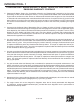
INTRODUCTION - 1 SAFETY INFORMATION REPLACEMENT PARTS “Safety Warnings” and additional information or instructions are used to alert the installer/operator of possible safety hazards in performing certain service or maintenance procedures incorrectly or carelessly. DANGERS and WARNINGS are accompanied by the international HAZARD symbol: These “Safety Warnings” alone cannot eliminate the hazards that they signal.
BOATING RESPONSIBILITIES - 2 To find out more about making boating safer, including how you can prevent carbon monoxide poisoning on recreational boats, contact: CARBON MONOXIDE HAZARD DANGER Carbon Monoxide (CO) is a colorless, odorless and tasteless gas. You cannot see it, smell it or taste it.
BOATING RESPONSIBILITIES - 2 SAFE BOATING SUGGESTIONS The nation’s waterways are becoming increasingly crowded and, in order to enjoy them safely, the operator should acquaint himself/herself with safe boating practices.
BOATING RESPONSIBILITIES - 2 RULES OF THE ROAD Channel Buoy Guide The color of the paint is the only characteristic which has the same meaning on all buoys. Red buoys always indicate the starboard side of the channel from seaward. (Red Right Returning) 2 5 1. Nun Buoy: This buoy indicates the starboard side of the channel when returning from sea. It is conical shape, the color red and indicates even numbers.
ENGINE IDENTIFICATION - 3 ENGINE IDENTIFICATION 5.7L 350 c.i.d MULTIPORT FUEL INJECTION When ordering service parts or obtaining information, always give the engine model and the serial number. This information can be found on the following decal. MAXIMUM CONTINUOUS CRUISE: 3800 RPM MAXIMUM ENGINE SPEED (WOT): 5000 RPM FUEL PRESSURE 48-52 @ Idle 53-57 @ W.O.T.
ENGINE IDENTIFICATION - 3 PCM 2004 MODEL IDENTIFICATION / ADVISORY MODEL P X L A P R R 123 M SERIAL 440000 1st Space: MANUFACTURER P - Pleasurecraft Marine 2nd Space: FACTORY FRESHWATER / CLOSED COOLING X-Freshwater Cooled (Space Omitted If Raw Water Cooled ) 3rd Space: ENGINE ROTATION L - Rotation, Left-Hand from Rear R - Rotation, Right-Hand from Rear 4th Space: ENGINE TYPE A = 5.7L (350 CID HO) Q = 6.0L (364 CID) G = 5.0L (305 CID STD) X = 8.1L (496 CID STD) Z = 8.
ELECTRONIC FUEL INJECTION INFORMATION - 4 ELECTRONIC FUEL INJECTION SYSTEM POWER REDUCTION MODE The PCM engines covered in this manual are equipped with an Electronic Fuel Injection (EFI) system, which allows precise control of fuel and spark delivery. The fuel system components of the EFI system are: • The electric fuel pump • The throttle body assembly • The fuel injectors The ECM monitors engine oil pressure and engine coolant temperature whenever the engine is running.
OPERATING INSTRUCTIONS - 5 ENGINE ALARM SYSTEM (IF EQUIPPED) The PCM engine electronic system is programmed to control the engine alarm system. This system utilizes an audible alarm and/or optional indicator lamps to warn the operator of possible engine problems, and that the engine have entered the “Power Reduction” mode as covered earlier in this manual. The alarm has a “self” checking feature programmed into the system.
OPERATING INSTRUCTIONS - 5 INSTRUMENTATION Boat manufacturers install many different types of instrumentation on boats. Become familiar with the instrumentation on your boat and be aware of abnormal operating conditions. The following is a brief explanation of typical instrumentation found on most boats: 1. Tachometer - indicates the engine RPM (revolutions per minute) 2. Engine Synchronizer (twin engines only) 3. Water Temperature Gauge - indicates the engine coolant temperature 4.
OPERATING INSTRUCTIONS - 5 STARTING ENGINE (FUEL INJECTED ENGINES) WARNING Before starting engine, ventilate the engine compartment by operating the bilge blower for a minimum of five minutes to remove any gas fumes from the engine compartment. If the boat is not equipped with a blower, open the engine compartment hatches to ventilate and leave open while starting engine.
OPERATING INSTRUCTIONS - 5 CLEAR FLOOD (100%) SHIFTING TRANSMISSION STARTING OR IDLE POSITION CAUTION Never shift the transmission into or out of gear unless the throttle is at the idle position. Shifting the transmission above 1000 RPM can severely damage the boat, transmission and engine. 1. Set the throttle lever at the idle position. 2. Move the transmission lever completely forward to shift into Forward gear. FULL THROTTLE (WOT) 3.
OPERATING INSTRUCTIONS - 5 STOPPING ENGINE FREEZING TEMPERATURE OPERATION When returning to the dock, or whenever stopping the engine, bring the throttle back to the idle position. After the engine reaches idle speed, turn the ignition key to the OFF position. If the possibility of freezing exists, the cooling system must be protected after the engine is shut off to prevent freeze damage to the engine. Refer to OUT-OFSEASON STORAGE for draining instructions.
CONDITIONS AFFECTING OPERATION - 6 TRIM AND WEIGHT DISTRIBUTION BOAT BOTTOM Trimming of the boat and positioning of the weight (gear and passengers) inside the boat has the following effects on handling: To ensure maximum engine performance, fuel economy and boat speed, the bottom of your boat must be kept clean and free of marine growth and barnacles. Marine vegetation may accumulate when the boat is docked and should be removed before operation.
CONDITIONS AFFECTING OPERATION - 6 PROPELLER SELECTION Best all-around performance and maximum engine life is achieved when the engine is propped to run near the top of (but within) the recommended full throttle RPM range with a normal load. See ENGINE SPECIFICATIONS for rated full throttle RPM for your model engine.
ENGINE BREAK-IN PERIOD - 7 WARNING CAUTION Use this procedure ONLY when conditions are such that it can be done in complete safety. DO NOT attempt to break in any engine by prolong idling, or running at the dock. The break-in period of your engine is the first 25 hours of operation. Proper engine break-in is essential to achieve maximum performance, longevity and minimum oil consumption.
25-HOUR ENGINE INSPECTION - 8 After the first 25 hours of operation, it is recommended that the engine be given an inspection. Your boat dealer or a PCM servicing dealer should be contacted to perform the necessary checks and adjustments to ensure the proper engine performance. The following maintenance should be performed: • Change the engine oil and filter. • Replace the primary fuel filter • Check the engine alignment. • Inspect the accessory drive belt(s) and check the tension.
FUEL REQUIREMENTS - 9 GASOLINE REQUIREMENTS GASOLINE CONTAINING ALCOHOL WARRANTY NOTICE: Damage caused to the engine through the use of improper gasoline, low-quality or gasoline with an octane rating below the minimum requirements listed below, is considered misuse of the engine. Such damage is not covered by the PCM Engines warranty. Gasoline containing alcohol, either ethanol (ethyl alcohol) or methanol (methyl alcohol) is not recommended for use in your engine.
OIL REQUIREMENTS - 10 WARRANTY NOTICE: PCM Engines reserves the right to refuse warranty on part(s) and/or engine(s) damaged by using improper fuels and engine oils. ENGINE OIL RECOMMENDATIONS Use of Supplemental Additives Engine oils meeting PCM Engines’ recommendations already contain a balanced additive treatment. The use of supplemental additives which are added to the engine oil by the customer are unnecessary and may be harmful. PCM Engines does not review, approve or recommend such products.
ENGINE MAINTENANCE - 11 ENGINE MAINTENANCE Refer to the MAINTENANCE SCHEDULE for a complete listing of required maintenance and the frequency at which it should be performed. Some procedures may be performed by the owner/operator while others should be performed by an authorized PCM Engines Dealer. Before performing any maintenance or repair procedure not covered in this manual, it is strongly recommended that a PCM Engines repair manual be purchased and read thoroughly.
ENGINE MAINTENANCE - 11 Transmission Fluid Hurth Transmission CAUTION WARNING PCM Engines uses marine transmissions supplied by several manufacturers. The maintenance requirements can be different between these manufacturers. It is important that you refer to the operation and maintenance manual supplied by the transmission manufacturer before you attempt to perform maintenance on your own.
ENGINE MAINTENANCE - 11 LUBRICATION Shift Cable Throttle Cable Lubricate pivot points and exposed cable (Figure 11-4) with SAE 30W-30 engine oil. Lubricate pivot points and exposed cable (Figure 11-3) with SAE 30W-30 engine oil.
ENGINE MAINTENANCE - 11 ELECTRICAL SYSTEM CIRCUIT BREAKER FUSE BLOCK Main Circuit Breaker PCM engines are equipped with a circuit breaker which provides electrical overload protection for both engine and instrumentation wiring and components. Should an electrical overload occur, the circuit breaker will open and prevent electrical current flow. When this circuit breaker opens, the cause for the high current draw must be found and corrected.
ENGINE MAINTENANCE - 11 BATTERY WARNING Follow maintenance instructions and warnings as supplied by the battery manufacturer. If this information is not available, follow these guidelines for the proper battery care. Battery electrolyte is a corrosive acid and should be handled with care. If electrolyte is spilled or splashed on any part of the body, IMMEDIATELY flush the exposed area with liberal amounts of water and obtain medical aid as soon as possible.
ENGINE MAINTENANCE - 11 FRESH-WATER COOLING SYSTEM SACRIFICIAL ZINC ANODE HEAT EXCHANGER PROTECTIVE ANODE ZINC ANODE Located in the raw water side of the heat exchanger is a zinc anode which is marked by a decal. To check, remove the plug and visually check the condition of the zinc rod. The length of the zinc rod when new is approximately 1.5 inches. If more than one half of the zinc is gone, replace with a new zinc anode.
ENGINE MAINTENANCE - 11 CHECKING COOLANT LEVEL COOLANT RECOVERY TANK WARNING Do not remove cooling system filler cap when the engine is hot. Allow the engine to cool and then remove the pressure cap slowly, allowing the pressure to vent. Hot coolant, under pressure, may discharge violently and cause severe burns. PRESSURE CAP Coolant Recovery Reservoir The “see-through” plastic reservoir is connected to the heat exchanger by a small hose.
ENGINE MAINTENANCE - 11 FLUSHING COOLING SYSTEM - SEA-WATER SECTION To prevent silt and/or salt build-up in the cooling system (fresh or raw-water cooled), flush the sea-water section of the cooling system with fresh water at specified intervals. Close seacock (if applicable) before removing inlet hose. CAUTION Do not operate the engine without sufficient amount of water being supplied to the sea-water pump. The sea-water pump impeller may be damaged and subsequent overheating damage may result.
ENGINE MAINTENANCE - 11 TESTING COOLANT FOR ALKALINITY WARNING It is recommended that the coolant in the fresh-water section be tested each year for alkalinity. Coolant that is not alkaline has lost the effectiveness of its rust inhibitors, which can lead to internal corrosion and cooling system problems. It is recommended to replace the standard ethylene glycol coolant in the system every two years to prevent a build-up of harmful chemicals within the fresh-water system.
ENGINE MAINTENANCE - 11 FILLING FRESH-WATER COOLING SYSTEM A new extended life engine coolant known as DEXCOOL™ is used in your engine(s). It is imperative to note the following about DEX-COOL™ engine coolant: • IT IS PINK IN COLOR TO DISTINGUISH IT FROM CONVENTIONAL COOLANT. • THE SERVICE CHANGE INTERVAL ON ENGINES BUILT WITH DEX-COOL™ IS 5 YEARS. • TO MAINTAIN FULL CORROSION PROTECTION DURABILITY, DEX-COOL™ MUST NOT BE MIXED WITH CONVENTIONAL (CONTAINING SILICATE) ENGINE COOLANTS.
ENGINE MAINTENANCE - 11 ANTIFREEZE SOLUTION Figure 11-12 Filling F.W.C. System (6.0L) CLEANING SEA-WATER SECTION OF HEAT EXCHANGER - FRESH-WATER COOLED MODELS ONLY HEAT EXCHANGER The sea-water section of the heat exchanger should be cleaned whenever there is a noticeable decrease in cooling efficiency.
ENGINE MAINTENANCE - 11 FUEL SYSTEM DESCRIPTION Fuel Control Cell (FCC) Fuel System WARNING Extreme caution must be exercised when servicing the fuel system and/or replacing fuel filter. Gasoline is extremely flammable and highly explosive under certain conditions. Be sure the ignition key is off and do not smoke or allow open flame in the area while servicing. Wipe up any spilled fuel immediately. WARNING Extreme caution must be exercised when servicing the fuel system.
ENGINE MAINTENANCE - 11 FUEL SUPPLY LINE FUEL RETURN LINE 5.0/5.7/8.1L ONLY TO FUEL TANK FUEL CONTROL CELL LOW-PRESSURE FUEL PUMP Figure 11-14 Fuel Control Cell (FCC) Fuel System (Typical) Servicing the FCC The frequency of draining the water or replacing the filter element is determined by the contamination level of the fuel. Replace the filter element at least once a year, or when a loss of power is noticed (whichever occurs first).
ENGINE MAINTENANCE - 11 Primary Fuel Filter WARNING Extreme caution must be exercised when servicing the fuel system. The fuel system operates under high pressure. Use caution when removing or replacing components, as residual pressure may be present. FUEL PRESSURE REGULATOR Draining the FCC Bowl, ENGINE OFF 1. Disconnect the two-wire electrical connector. 2. Hold the 3/4” jam nut, located at the bottom of the FCC bowl, with a wrench.
ENGINE MAINTENANCE - 11 8. Lubricate the new O-ring with a light grease and install the new O-ring into the FCC bowl mounting head. 9. Apply pipe sealant, suitable for use with gasoline, to the threads of the 7/16” plug. 10. Install and tighten the 7/16” plug while holding the 3/4” jam nut with a wrench. 11. Grease taper and the threads on the FCC bowl and, by hand, thread the FCC bowl into the FCC mounting head. Tighten the bowl firmly back into the mounting head with an oil filter wrench. FUEL PUMP 12.
ENGINE MAINTENANCE - 11 FLAME ARRESTOR FASTENERS WARNING FLAME ARRESTOR Make sure there are no fuel leaks before closing the engine hatch. Priming Fuel System To prime the fuel system, cycle the ignition key 3 times using the following procedures: 1. Turn ignition key to ON position for 5 seconds. 2. Turn ignition key OFF. 3. Pause for 10 seconds. THROTTLE BODY 4. Repeat steps 1-3 three times. Figure 11-16 Flame Arrestor - 5.7L (Typical) Crank the engine until it starts or 30 seconds elapse.
ENGINE MAINTENANCE - 11 DRIVE BELT INSPECTION CAUTION Inspect the drive belt for excessive wear, shredding or missing sections. Inspect the drive belt for contamination from excessive dirt, oil, coolant or other substances that may effect the drive belt operation.
ENGINE MAINTENANCE - 11 7. Compress the belt tensioner, and slide the belt over the tensioner pulley. Release the tension slowly to tension the belt. 8. Position the bracket onto the sea-water pump anchor boss, and install the flat washer, lock washer and bolt to the pump. 9. Tighten the bracket-to-engine block attaching bolts to 18 lb. ft. 10. Tighten the bolt that secures the sea-water pump to the bracket to 12 lb. ft. 11. Install the inlet and outlet hoses to the sea-water pump.
ENGINE MAINTENANCE - 11 6.0L ACCESSORY DRIVE BELT The PCM 6.0L engine uses a single serpentine belt to drive the engine water circulation pump, sea-water pump and the alternator. DRIVE BELT REPLACEMENT (6.0L) 1. Note the routing of the belt before removing. 2. Using a 15 mm box wrench or socket, turn the belt tensioner to relieve the tension on the belt. Slide the belt off of the pulleys.
ENGINE MAINTENANCE - 11 WARNING Engine must be shut OFF and the ignition key removed before inspecting the drive belt(s). The drive belt(s) should be checked periodically for condition and tension. If the belt(s) shows signs of cracking, glazing or deterioration, replace with new belt(s). 5.0/5.7L ACCESSORY DRIVE BELT The PCM 6.0L engine uses a single serpentine belt to drive the engine water circulation pump, sea-water pump and the alternator. DRIVE BELT REPLACEMENT (5.0/5.7L) 1.
ENGINE MAINTENANCE - 11 CHANGING OILS OIL PUMP WARNING IMPORTANT: The Federal Water Pollution Control Act prohibits the discharge of oil or oily waste into or upon the navigable waters and continuous zone of the United States, if such discharge causes a film or sheen upon, or discoloration of the surface of the water, or causes sludge or emulsion beneath the surface of the water. Violators are subject to a penalty of $5,000.00. DIPSTICK Refer to the MAINTENANCE SCHEDULE for oil change intervals.
ENGINE MAINTENANCE - 11 ENGINE ALIGNMENT CAUTION Engine must be properly aligned, or vibration, noise and damage to the transmission output shaft oil seal and bearings may result. A IMPORTANT: Engine alignment MUST BE RECHECKED with the boat in the water, fuel tanks full and with a normal load on the boat. Engine must be aligned so that the transmission and the propeller shaft coupling center lines are aligned, and coupling faces are parallel within 0.003 in. (0.07 mm).
ENGINE MAINTENANCE - 11 .003 INCH (0.07 mm) FEELER GAUGE • TRANSMISSION OUTPUT FLANGE PROPELLER SHAFT COUPLING FLANGE LEFT or RIGHT ADJUSTMENT: Loosen the trunnion clamping bolt and the nut on all four mounting brackets. Move the engine to the left or right, as necessary, to obtain the proper alignment. After adjustment is complete, tighten all bolts. LOCKING NUT STRAIGHT EDGE Figure 11-29 Angular Alignment OFFSET ALIGNMENT: 4.
ENGINE MAINTENANCE - 11 .003 INCH (0.07 mm) FEELER GAUGE Angular Misalignment Front Mount Adjusted A Both B Trunnion LC R RC L TRANSMISSION OUTPUT FLANGE PROPELLER SHAFT COUPLING FLANGE • STRAIGHT EDGE Figure 11-33 Angular Alignment 5. Check for any angular misalignment. Hold coupling faces tightly together by hand and check for a gap between the coupling faces, with a 0.003 in. (0.07 mm) feeler gauge, at 90-degree intervals. (Figure 11-34).
ENGINE MAINTENANCE - 11 ENGINE MAINTENANCE LOG Date Operating Hours Maintenance/Repair L510010-04 51
ENGINE MAINTENANCE - 11 MAINTENANCE SCHEDULE Location and Service Check Daily Check coolant level - Fresh-water cooled models only X Check oil level - Engine crankcase X Check oil level - Transmission X Engine Assembly (complete - Check for obvious leaks (water, oil, fuel and exhaust) X Remote Control and Steering System Check for proper operation X Sea Strainer - Check (if equipped) X Cooling System - Check condition and tightness of all hose clamps After 1st 25 Hrs of Operation Every 50 Ho
ENGINE MAINTENANCE - 11 MAINTENANCE SCHEDULE (cont’d) Every 100 Hours of Operation Once Each Year Hoses (all) - Inspect for cracks, swelling, weather checking or other signs of deterioration X X Shift and Throttle Cable Linkage - Inspect and lubricate (A) X1 X O O Location and Service After 1st 25 Hrs of Operation Check Daily Fuel Filters - Service or replace O Transmission and “V” Drive - Change fluid (B,C) and clean strainer, if equipped O Every 50 Hours of Operation O MAINTENANCE SCHEDU
ENGINE MAINTENANCE - 11 VISUAL INSPECTION It is important for the owner/operator to visually inspect the complete engine assembly at regular intervals. Most often, costly repairs can be avoided if potential problems are corrected before there is a failure. Touch up scratches, nicks and corrosion damage to the exterior finish of the engine. Spray paint may be obtained from your local PCM Engines dealer.
ENGINE MAINTENANCE - 11 FILTER REQUIREMENTS Description Part No.
56 L510010-04 Battery Rating 650 CCA (Minimum) 120 Ah 43-47 degrees CAM Retard 70 Amps Alternator Rating Not Adjustable 12 Volt Negative (-) Ground Electrical System Ignition Timing 193° F (89.8° C) RWC 160˚F (61.7˚C) FWC 170˚F (76.7˚C) Thermostat Over- Temperature 1-8-4-3-6-5-7-2 (LH) 1-2-7-5-6-3-4-8 (RH) R030010 0.060 in.
44-48 psi @ WOT MY ‘03 Only 57-60 psi @ WOT MP 6.0L (375 HP) 4 - 7 psi (WOT) 4 - 7 psi (WOT) 4 - 7 psi (WOT) IMPORTANT: FUEL PRESSURE MEASUREMENT MUST BE MADE WITH THE ENGINE UNDER LOAD. 4 - 7 psi (WOT) 4 - 7 psi (WOT) 44-48 psi @ WOT MP 8.1L (HO) (425 HP) Fuel Pressure - LPFP ALL ENGINES 57-62 psi @ WOT MP 8.1L (STD) (385 HP) MY ‘04 59-61 psi (WOT) 57-62 psi @ WOT Fuel Pressure STD. FCC MP 5.7L (330 HP) PCM MASTER FUEL PRESSURE SPECIFICATIONS Fuel Pressure - FCC Returnless to Rail MP 5.
ENGINE SPECIFICATIONS - 12 5.0 / 5.7 Liter LH ROTATION 6.0 / 8.1 Liter LH ROTATION FRONT FRONT 2 1 2 3 4 3 4 5 6 5 6 7 8 7 8 8 1 2 NO DISTRIBUTOR 4 1 6 7 c 3 5 Rotation FLYWHEEL END OF ENGINE ALL V-8 MODELS FIRING ORDER: 1-8-4-3-6-5-7-2 FIRING ORDER: 1-8-7-2-6-5-4-3 Figure 12-1 V-8 Firing Orders TUNE-UP SPECIFICATIONS MP 5.0L (275 HP) MP 5.7L (330 HP) MP 6.0L (375 HP) MP 8.1L(STD) (385 HP) MP 8.1L (HO) (425 HP) Spark Plug Type R030010 R030011 R030009 Spark Plug Gap 0.
OUT-OF-SEASON STORAGE - 13 5. Turn off the ignition and remove the spark plugs. Use an aerosol-type fogging solution and spray a sufficient amount into each cylinder. (Spray 5 seconds per cylinder, minimum.) Turn the crankshaft several revolutions by hand to spread the oil evenly throughout the cylinders. ENGINE STORAGE IMPORTANT: These services should be performed by an Authorized PCM Dealer.
OUT-OF-SEASON STORAGE - 13 DRAINING INSTRUCTIONS CAUTION If the boat is to remain in the water during or after draining, close the seacock to prevent a siphoning action that may occur, allowing sea water to flow from drain holes or removed hoses. LARGE HOSE IMPORTANT: When removing the drain plugs, insert a wire into the hole to remove any obstruction which would prevent water from draining completely. DRAIN LOCATION RAW-WATER COOLED MODELS 1.
OUT-OF-SEASON STORAGE - 13 4. Remove the raw water pump impeller. (See ENGINE MAINTENANCE) If inspection proves the impeller to be in good condition, store it in an accessible spot for re-installation at the end of the storage period. A damaged or badly worn impeller should be discarded and a new one installed at the end of the storage period. 9. Reinstall the hoses into the thermostat housing and tighten the hose clamps securely.
OUT-OF-SEASON STORAGE - 13 RECOMMISSIONING AFTER STORAGE CAUTION IMPORTANT: These services should be performed by an Authorized PCM Dealer. When recommissioning the engine after storage, the following items should be checked: Failure to remove the excess storage oil from the engine’s cylinders can cause hydrostatic locking to occur, and severe damage to the engine. 8. Before starting the engine, be sure there is not an excess amount of storage oil left in the cylinders. Remove the spark plugs.
TROUBLESHOOTING - 14 Engine performance complaints usually fall under one of the basic headings listed in the Troubleshooting Guide. When a problem cannot be easily diagnosed, consult a PCM Engines Servicing Dealer for assistance. Malfunction Possible Cause Corrective Action Engine will not crank with the starter motor, or cranks slowly. Problem with the engine management system. Contact PCM Engines Dealer. Battery switch turned OFF (if equipped) Turn the battery switch ON.
TROUBLESHOOTING - 14 Malfunction Possible Cause Corrective Action Engine Overheats Loose or worn drive belt(s) Adjust or replace the belts as necessary. Collapsed, kinked or leaking hoses. Replace the hoses. Transmission/engine oil cooler plugged Remove the water hoses and flush in opposite direction of the normal flow. Faulty thermostat Replace the thermostat. Sea-water intake valve partially/fully closed. Open the valve completely. Restricted sea-water pickup Remove restriction.
TROUBLESHOOTING - 14 Malfunction Possible Cause Corrective Action Transmission slipping erratic operation Low oil level Add specified oil. Check the transmission for leaks. Transmission overfilled causing oil aeration Drain required amount of oil. Transmission shift lever not fully engaged Adjust the shift linkage and remote control. Check the shift cables for freedom of movement and binding. Contaminated fluid Determine and correct the contamination source and change the fluid.
Figure 15-1 Raw-Water Cooling System (5.0/5.7L Modular Raw Water Pump) L510010-04 66 = Drain Locations = RAW WATER FLOW Knock Sensor Torque 20 N.
= Drain Locations = RAW WATER FLOW = FRESH WATER FLOW WATER FLOW DIAGRAMS - 15 Figure 15-2 Fresh-Water Cooling System (5.0/5.
WATER FLOW DIAGRAMS - 15 3 4 2 1 A 2 Remove Hose from raw water pump and drain hose completely 5 6 1 7 = RAW WATER FLOW = FRESH WATER FLOW = 7 Drain Locations IMPORTANT: Accessory (i.e. heater, hot water tank) Hook Up A tee may be inserted anywhere in the specified hose for most appropriate routing. Location 1 - Water OUT to heater or hot water tank Location 2 - Water RETURN from heater or hot water tank NOTE: Location A is the cooling system bypass. This bypass hose MUST NOT be tampered with.
WATER FLOW DIAGRAMS - 15 DRAIN = Optional Drain Kit The drain kit does not ensure that all of the water will drain out of the system. Engine angle, routing of drain hose, and restricted drain fittings are some things that could prevent all of the water from draining completely. Figure 15-4 Water Drain kit - Optional (6.
Figure 15-5 Raw-Water Cooling System (8.
= Drain Locations = FRESH WATER FLOW = RAW WATER FLOW To Engine Block To Engine Block WATER FLOW DIAGRAMS - 15 Figure 15-5 Fresh-Water Cooling System (8.
INSTRUMENTATION WIRING DIAGRAMS - 16 ENGINE HARNESS WIRE HARNESS COLOR CHART CIRCUIT NUMBER CIRCUIT NAME ENGINE HARNESS WIRE COLOR 1. 2. 3. 4. 5. 6. 7. 8. 9. 10. GROUND TACHOMETER WATER TEMPERATURE ENGINE ALARM IGNITION BATTERY STARTER OIL PRESSURE CHECK ENGINE LIGHT DATA LINE BLACK GRAY TAN TAN/BLACK PURPLE/WHITE RED/WHITE YELLOW/RED LT. BLUE BROWN/WHITE ORANGE/BLACK 1 2 10 3 4 NOTE A : POWER FOR A FUSED ACCESSORY PANEL MAY BE TAKEN FROM THIS LOCATION. LOAD CANNOT EXCEED 30 AMPS.
LITERATURE - 17 To obtain service and/or parts literature for your PCM Marine Engine, contact the following: PCM Engines Pleasurecraft Engine Group Publications Department 1737 Highway 76 East Little Mountain, SC 29075 1. SERVICE: For more detailed information, PCM has a detailed service manual available. This manual contains complete engine and component disassembly and reassembly instructions. Troubleshooting and maintenance charts are also included. 2.
FORMS - 18 PCM WARRANTY TRANSFER APPLICATION The remainder of the original PCM limited warranty is transferable within thirty (30) days of date of sale by the original owner/user to a subsequent purchaser for the remainder of the unused portion of the original warranty term, provided the engine does not have in excess of 300 hours. The original date of sale or original in-service date (whichever comes first) begins the warranty coverage period.
FORMS - 18 PCM SUMMARY OF WARRANTY TERM LIMITS This list does not, in any way, modify the official Limited Warranty Statement of PCM. This list has been compiled only as a general outline of year and hour limits imposed on different models of PCM engines. Please review the official Limited Warranty Statements on the following pages for specific terms and limitations as they apply to the particular engine / component involved. ENGINE MODEL YEAR: WARRANTY COVERAGE TERM: 1992 & OLDER 1 year, 200 hours.
FORMS - 18 OPERATION AND MAINTENANCE LOG Engine Model and Serial # Port Drive Port Ignition Key Port Stbd. Serial # Stbd. Number Stbd. Fire Extinguisher Checked Runs Made Date Gal of Fuel Qts of Oil Port Stbd.
FORMS - 18 PROBLEM NOTIFICATION OR INFORMATION REQUEST FORM IMPORTANT: All blanks MUST be completed to insure proper identification of your engine which is necessary to properly understand your request.
NOTES - 19 L510010-04 78