REVERSE OSMOSIS DRINKING WATER SYSTEMS INSTALLATION, OPERATION & SERVICE MANUAL 220 Bayview Drive, Unit 18 Barrie, ON L4N 4Y8 www.excaliburwater.
TABLE OF CONTENTS INTRODUCTION . Page 1 PREPARATION A. Major System Components Installation Drawing B. Tools Recommended for Installation C. Site Selection For Major System Components 2 3 4 4 INSTALLATION STEPS A. Faucet Installation Faucet Drawing B. Feed Water Ball Valve Installation C. Drain Clamp Installation D. Position the Drinking Water Holding Tank and Make the Final Hose Connections E. Start Up 5 6 7 8 9 9 OPERATION AND MAINTENANCE A. Normal Operation B. Changing Filters C.
The membrane is a specially constructed, Fully aromatic polyamide film, and is classified as a Thin Film Composite (T.F.C.). The spiral wound construction of the Reverse Osmosis Membrane provides maximum surface area for water production and is less susceptible to fouling by particulate matter, turbidity and colloidal materials. INTRODUCTION Your new Reverse Osmosis Drinking Water System uses a combination of filtration technologies to reduce unwanted contaminants in your water supply.
PREPARATION A. Major System Components The following components comprise the Reverse Osmosis Drinking Water System. (Refer to Fig. 1, below for general system layout.) 9. A Sediment Pre-filter, shrink wrapped. 6. A Drain Clamp. 10.An activated Carbon Pre-filter, shrink wrapped. 11.An In-Line Activated Coconut Shell Carbon Post Filter. 12.Other items necessary for installation may include wood screws or machine screws and nuts for mounting the manifold, or concrete anchors for hanging on basement wall.
BALL 3 C.
C. Site Selection for Major System Components B. Tools Recommended for Installation The Reverse Osmosis System was designed to fit under a sink, however, because of space limitations or other reasons, the system's flexible design allows for other locations. When determining the location remember that access to a cold water tap line, the household drain, and ease of filter replacement are important considerations. The following tools will cover most of the installation sites encountered: 1.
2b. Drilling a porcelain sink: 4. Feed Water Connection – The Feed Water Ball Valve should be located as close to the manifold assembly as possible. USE A POTABLE COLD WATER SUPPLY ONLY. Softened water is preferred as it will extend the life of the Reverse Osmosis Membrane. It is best to use a special 1¼" diameter cutter designed for porcelain. A carbide tipped masonry bit is a second choice. • Place a piece of tape over the area to be drilled to help prevent chipping.
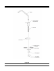
LONG REACH FAUCET Figure 2A 6
B. Feed Water Ball Valve Installation 3. With the Feed Water Ball Valve closed, open the sink faucet and the water supply and allow the water to run for a few minutes to flush any debris caused by the installation. Decide on location. Do NOT connect to a hot water feed line. If you are not sure of the supply, run the hot water and feel the supply piping. Water over 100ºF may cause permanent damage to the Reverse Osmosis Membrane. (Refer to Fig. 3 page 8.) 1. Shut off the water supply and drain the line. 2.
3. Locate the 3/8" Black Drain Tubing connected to the Reverse Osmosis Unit. Route to the tubing to the Drain Clamp and trim to length. C. Drain Clamp Installation Choose the drain outlet location. The following are instructions for discharging in the sink drain pipe. (Refer to Fig. 1, page 3) NOTE: When cutting the polytubing make clean, square cuts, failing to do so could result in poor connections and possible leaks. 1. Position the Drain Clamp on the sink drain pipe above the drain trap.
• Slowly open the Feed Water Ball Valve (turning counter clockwise). D. Position the Drinking Water Holding Tank and Make the Final Hose Connections • As soon as the water begins to come out of the Dispensing Faucet, close the Faucet. 1. Check the tank pre-charge pressure. Make sure it is between 5 to 7 psig. If not, use a bicycle hand pump or other pump to bring the pressure up to the 5 to 7 psig range. • Let stand for 15 minutes. NOTE: During this time, check the system carefully for leaks. 2.
Use a drip pan to catch any water that may spill when the Filter Housings are removed. Refer to Fig. 1, page 3 for component location. OPERATION & MAINTENANCE A. Normal Operation 1. Reverse Osmosis systems produce drinking water at relatively slow rates, it can take up to 3 hours to fill the Holding Tank. Normal operation is to let the Holding Tank fill with water and then draw water as is needed.
3 ml) into the tubing and reconnect it to the Tee. 5. Slowly open the Feed Water Ball Valve. 6. When water begins dripping out of the Faucet, in the following order, close the Faucet and open the Holding Tank Valve. When the Faucet is first opened, expect air and carbon fines (very fine black powder), from the new Post Filter to be rinsed out. This is normal for the first tank of water. NOTE: Now is the convenient time to change the In-Line Activated Carbon Post Filter.
TROUBLE SHOOTING GUIDE Problem Low quantity of Product Water from Holding Tank Possible Cause Feed Water Ball Valve is plugged or closed. Clogged Sediment Pre-filter or Activated Carbon Pre-filter. Low water pressure. Reverse Osmosis. Membrane is fouled. Plugged In-Line Activated Carbon Post Filter. Air pre-charge pressure in Holding Tank is too high. Air pre-charge is too low Low pressure at the Dispensing Faucet Air Bladder in the Holding Tank is ruptured. Holding Tank Valve is closed.
Problem High Total Dissolved Solids (TDS) in the Product Water (continued) Possible Cause The Product Water and Drain Water lines are reversed. No drain flow, Drain Restrictor is clogged. The ASO Valve is not closing. New In-Line or Activated Carbon Pre-filter not rinsed completely. The Feed Water TDS has increased. Tastes and odors in the Product Water Drain Water overflows at the Air Gap Faucet Faucet leaks or drips The In-Line or Activated Carbon Pre-filter is exhausted.
14