A Higher Level of Precision… A Higher Level of Performance Intell-Weigh 10™ Indicator NTEP Approved 10,000 Divisions, COC # 10-010 User Operation Manual
Table of Contents Safety Precaution ....................................................................................................................... 3 Chapter 1 Keypad Instruction ................................................................................................... 3 Chapter 2 Specifications ........................................................................................................... 4 Chapter 3 Front and Rear Panels ........................................................
FM/FMR 2 ZSME300000103
Before using the product Thank you for purchasing EXCELL FM / FMR indicator. In order to operate smoothly, to last the durability, and to reduce the chance of breakdown for this product, please read this User Manual carefully. Safety Precaution Turn off power before installing or disassembling. Keep the product away from sunshine. The temperature range for operation is 0 ~ +40 ℃. To connect the ground is a must for this equipment. The ground impedance is less than 100 .
Function General Function Setting Operation Press and hold and then press , ENTER F1 Refer to External Function Parameter Setting for details Weighing Parameter Setting Adjust calibration switch to ON Setting for decimal point, capacity, division, zero tracking, and unstable detection, etc. Refer to 6-1 Specification Setting for details. Calibration Adjust calibration switch to ON Refer to 6-2 Weight Calibration for details.
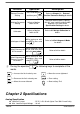
Input Sensitivity Conversion Rate Resolution : 0.15 V/d or more : Approximately 120 times/s (max.) : 20 bits Digital Specification Display Display Frequency Display Range Min. Division Decimal Point Memory : LCD, 6 digits, 25.4 x 10 mm (W x H), LED backlight (Black digits for FM; Red digits for FMR) : 50 times/s (max) : - 999 999 ~ 999 999 : 1, 2, 5, 10, 20, 50 : 0, 0.0, 0.00, 0.000, 0.0000 : Calibration parameter and function setting are all stored in EEPROM.
Chapter 3 Front and Rear Panels 3-1 Front Panel R + - TARE ESC MOTION ZERO + M+ TARE GROSS GROSS NET PT RANGE 1 F2 RANGE2 F1 ENTER Indication: : Battery charged status (only available to charged model) : TARE : MOTION : M+ : GROSS : PT : RANGE1 : RANGE2 : Battery charging status (only available to charged model) Tare mode Unstable weighing indication Accumulation mode indication Gross weight Pre-Tare Dual-range resolution indication (1) Dual-range resolution indication (2) Keypad: ESC 1
3-2 Rear Panel 1 2 5 3 4 MINI INDICATOR後蓋(ABS) ABS RoHS材質限制: ˙ 鎘:100ppm以下 ˙ 鉛、汞、六價鉻、多溴聯苯、多溴二苯醚:1000ppm以下 1. Battery Case 2. RS-232 / RS-485 Input / Output 3. DC 9 V Power Input 4. Calibration Switch 5.
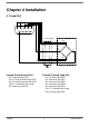
Chapter 4 Installation 4-1 Load Cell 4 5 9 2 3 8 7 1 6 Load cell cable Load cell EXC+ SEN+ SIG+ SIG- EXCSEN- Shield 4-wired (5-wired) Load Cell 6-wired (7-wired) Load Cell Pin 1 connects with SIG+ Pin 2, 3 short to connect with EXCPin 4, 5 short to connect with EXC+ Pin 6, 7, 8 connects with shield Pin 9 connects with SIG- FM/FMR Pin 1 connects with SIG+ Pin 2 connects with EXCPin 3 connects with SENPin 4 connects with SEN+ Pin 5 connects with EXC+ Pin 6, 7, 8 connect with shield Pin 9 c
4-2 Dimensions FM/FMR 9 ZSME300000103
4-3 Battery Assemble 將多餘的電線塞入電池孔中 Stuff the surplus wires into the battery case.
Chapter 5 External Function Parameter Setting Under general weight display status, press F1 ENTER , and the screen will show: ENTER Press ZERO Press TARE key key ENTER ESC Press to escape. Back to weight display status.
5-1 b External Press Function Setting ENTER *Parameter Code Key Disable Select the desired parameter code with ZERO / DSP Update (Display Update) F1 Key Function Setting TARE F2 Key Function Setting Press ENTER+F2 Function Setting ENTER Backlight Function Setting Beeper Setting The screen shows previous parameter setting. Press Press ESC ENTER .
External Function Parameter Setting Parameter Code Function FNC-00 Key disable FNC-01 FNC-02 FNC-03 FNC-04 FNC-05 FNC-06 FM/FMR DSP Update F1 Key Function Setting F2 Key Function Setting ENTER+F2 Function Setting Backlight Setting Beeper Setting 0000 1111 Default Setting Setting Value Description Parameter 0 ON 0000 is corresponding to:(from left to right) ZERO 1 OFF TARE GROSS NET 0000 F2 0 No Limit 1 20 times/s 2 10 times/s 3 5 times/s 4 1 times/s 0 Print (
5-2 RS-232 Setting *Parameter Code Information Pattern ENTER Press Transmission Method Transmission Rate Select the desired parameter code with ZERO / Parity, Bit Length, Stop Bit Unstable or Over Load TARE Auto Transmission Condition Command Address Press ENTER Output Format Transmission Times The screen shows previous parameter setting. ENTER Press to finish your any changes Press ESC Date Setting Time Setting to escape the setting.
OP-01 / RS-232 / RS-485 Interface Function Parameter Code Function RS1-00 Information Pattern (Please refer to page 16) RS1-01 Transmission Method RS1-02 Transmission Rate RS1-03 Parity, Bit Length, Stop Bit RS1-04 Unstable or Over Load RS1-05 Auto Transmission Condition RS1-06 Command Address RS1-07 Output Format FM/FMR Setting Value Default Setting Parameter Description 0 Display Correspondingly 1 Gross Weight 2 Net Weight 3 Tare 0 4 Weight Accumulation Value 5 Times Accumulation Val
FM/FMR RS1-08 Transmission Times RS1-09 RS1-10 Date Setting Time Setting 0 1 2 3 4 5 No Limit 1 times/s 2 times/s 5 times/s 10 times/s 20 times/s YY.MM.DD HH.MM.
Transmission Format RS1-00 0 ~ 3 S , T Header 1 G S , + 1 Header 2 2 3 . 4 5 6 g CR LF Weight Data (8 digits) Unit Terminators Header 1 ST: Stable Weight / US: Unstable Weight / OL: Weight Overload Header 2 GS: Gross Weight / NT: Net Weight / TR: Tare Weight Data (8 digits) The first digit of weight data represents “+ / -“indication for weight value. The other 7 digits, including decimal point, represent the weight value.
Command Mode Command Function Command Function READ / RW Weight Reading CT Tare Clearing ZERO / MZ Weight Re-zeroing Rl Weight Accumulation Rm Times Accumulation TARE / MT Gross Weight Deducting NTGS Gross / Net Switch Rn Date MG Gross Weight Indicating Ro Time MN Net Weight Indicating AT DT Weight and Times Accumulation Weight and Times Accumulation Clearing After setting the commands mentioned above, it’s a must to add the termination code “CR (0DH) and LF (0AH)”.
Chapter 6 Internal Calibration Adjust calibration switch to “ON”, and the screen displays: After 2 seconds ENTER Press ZERO Press TARE ENTER Press ZERO Press TARE ENTER Adjust calibration switch back to “OFF”.
6-1 Specification Calibration *Parameter Code Press ENTER Decimal Point Maximum Weighing Capacity Division 1 Select the desired parameter code with ZERO / Division 2 TARE Zero Tracking Setting Unstable Detection Setting Press ENTER The screen shows previous parameter setting. Press Press ESC ENTER .
Specification Parameter Description Parameter Function Code Parameter CSP-00 Decimal Point CSP-01 Maximum Weighing Capacity 999 999 000 000 Setting Value Description Default Setting Refer to the description on next page 0 Max. value for weight display 999 999 Min. value for weight display 1 Min.
Parameter Display Description CSP-00 Decimal Point Display Decimal Point Digit None CSP-04 . 1 digit . 2 digits . 3 digits . 4 digits Zero Tracking Setting Display Division/Time 0.25 d / 1 s . 0.5 d / 1 s . 0.75 d / 1 s . 1d / 1 s 1.25 d / 2 s . 1.5 d / 2 s . 1.75 d / 2 s . 2 d / 2s No Zero Tracking CSP-05 Unstable Detection Setting Display Division / Time 0.25 d / 1 s . 0.5 d / 1 s . 0.75 d / 1 s . 1d / 1 s 1.25 d / 2 s . 1.5 d / 2 s . 1.75 d / 2 s .
6-2 Weight Calibration Turn on and warm up the machine for 15 to 30 minutes before calibration. Adjust the calibration switch to “ON”, and the screen will show TARE ZERO Press or to select . .
Password Setting Adjust calibration switch to “ON” After 2 seconds ZERO F1 Input new password “0000” means no password. ENTER Confirm new password (re-input again) ENTER After complete password setting, when entering calibration mode or function setting mode, the screen shows for 1 second, and then . It’s necessary to input the correct password to continue each setting. If the input password is not correct, the screen shows FM/FMR 24 .
6-3 Internal Function Setting Press ENTER *Parameter Code Tare or Zero Function under Unstable Status Select the desired parameter code with ZERO Re-zeroing after Turning on ZERO Re-zero Range / Filter Strength Press ENTER Animal Scale Sampling Rate Animal Scale Mode The screen shows previous parameter setting. Animal Scale Stable Range Animal Scale Sampling Frequency ENTER Press to finish your any changes.
Internal Function Parameter Description Setting Value Description Parameter Code Function 0 ON CFN-00 Tare or Zero Function under Unstable Status 1 OFF Re-zeroing after Turning on 0 OFF 1 ON CFN-02 Re-zero Range 0% ~ 30% 0%: Full range re-zero 1% ~ 30%: Capacity setting value% 2 CFN-03 Filter Strength 0~5 Strength increases by number 2 0 1 2 3 0 No limit 20 times/s 10 times/s 5 times/s OFF Mode 1: No weight shows under unstable status Mode 2: Weight shows no matter under stabl
6-4 Error Messages (1) Load Cell or A/D circuit is abnormal (2) Real weighing value is lower than or equal to zero value (3) Internal resolution is lower than 0.15 μV/d range (4) .
Chapter 7 Special Function 7-1 Animal Scale Setting CFN-05 = 1 (Animal Scale Mode1: No weight display under unstable status) When there is nothing on the platter, the screen will show: When an object is on the platter, taking an object of 20 g as an example, the screen will show: .
7-2 Dual Range Resolution Switch Function If the setting of CSP-02 is not the same as CSP-03, the dual range resolution will be available.
7-3 Pre-Tare Function FNC-02 or FNC-03 setting is at parameter 6. (Pre-Tare Function) Under weight display status, press screen will show: F1 or F2 key (according to FNC setting), the Input the desired Pre-Tare value Press ENTER key Back to weight display status (PT indication lights up) Pre-Tare Cancellation When the gross weight column shows “0”, press TARE key to cancel the Pre-Tare value. 7-4 Resolution Switch Function FNC-02 or FNC-03 setting is at parameter 5.
Chapter 8 Interface 8-1 OP-01 RS-232 / RS-485 Serial Output with RTC (Real Time Clock) CN2 CN3 CN2 CN3 123 123 123 123 Short 1 and 2 pins to get RS-485 output. Pin Allocation of Rear Panel 4 5 9 Short 2 and 3 pins to get RS-232 output. 8 1 2 3 7 6 Pin Function 2 RXD 3 TXD 5 SG 6 DA 7 DB RS-485 interface is capable to connect up to 10 mini-indicators.
Connection Description (RS-485) Terminal Resistant Host EX0419 # 1 RS - 06 = 01 EX0419 # 2 RS - 06 = 02 EX0419 # 10 RS - 06 = 10 Notice If the terminal resistant is built-in the host interface, it’s not necessary to connect with another one outside. If the host computer is no signal ground (SG), it’s not necessary to connect with it.
Chapter 9 Maintenance 9-1 Default Recovery for All Parameters (1) Adjust the calibration switch to “ON”, when re-zeroing after turning on, press F1 ENTER and hold them simultaneously. . (2) The screen will show ENTER (3) To confirm, press and hold until showing calibration switch to “OFF”. , and then adjust the 9-2 Default Recovery for General Function Parameters (1) When re-zeroing after turning on, press ENTER ENTER and hold simultaneously. .
9-3-1 Program Version Number 7-Segment display shows program version number XX. 9-3-2 7-segment Display Testing 7-Segment display shows to and “.”. 9-3-3 Keypad & Calibration Switch Testing Adjust calibration switch to “ON”, and press any key, the corresponding bit will be changed from 9-3-4 to . A/D Conversion Value 7-Segment display shows the internal value of the scale. 9-3-5 EEPROM Testing Showing represents in normal condition. Showing represents in abnormal condition.
Appendix 7-SEGMENT DISPLAY CHARACTERS Number Letter Display Letter 0 A N 1 B O 2 C P 3 D Q 4 E R 5 F S 6 G T 7 H U 8 I V 9 J W K X L Y M Z ℃ FM/FMR Display 35 Display ZSME300000103
Intelligent Weighing Technology has more than 50 years experience in the weighing industry,both in the USA and worldwide. With contacts in over 50 countries including the USA, we provide you with the weighing equipment you need. When you invest in weighing equipment from Intelligent Weighing Technology, you’re really buying peace of mind. Quality - Scales and balances solidly built from the ground up with superior engineering and components for exacting results.