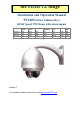
the excelPTZ range Installation and Operation Manual PTZ605 series Iridium Silver HIGH Speed PTZ Dome with alarm inputs Option F Option J Option K Optical Zoom Total Zoom Day/Night IR Sensitive Minimum Lux TVL Nite Plus 22x 22x 27x 352x 352x 270x YES YES YES NO YES YES 0.5 0.5 0.001 480 500 500 NO NO YES Version 7 For updates to these instructions visit www.excelPTZ.
CONTENTS TABLE Description Contents Safety Precautions Key Functions Special Dome Features –4 channel alarm input activation & channel alarm output Getting the dome up & running Overview –introduction to fitting PTZ equipment RS485 Wiring methods & Tips Overcoming RS485 data loss using an RS485 distributor Setting up the Dome Camera RS485 connection –Connecting the Keypad or DVR to the Dome Connecting the video out of the dome If you are using more than one dome on a site Setting up a unique address in a do
Please read this operation manual carefully before installing and using this unit !!!! Please read the following; 1. Please read the operation manual carefully before installing and operating the product. 2. The actual dome requires a 24v AC power supply. The rated input voltage of the camera is 12V!!!! This gets its power from the dome and does not require a separate PSU. Do not connect 24V AC to the camera under any circumstances!! 3.
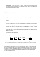
KEY FUNCTIONS Description of Functions This intelligent dome camera is a hi-tech CCTV product, which incorporates a high-clarity colour camera. It has a panoramic variable speed PAN/TILT movement, a multifunctional decoder, a character generator and an on-board processor for logic handling. The dome is easy to connect, install, maintain and operate, and has many features. The dome is compact and has a strong structure with a modern and appealing appearance. 1. Integrated Multi-Protocol Decoder a.
4. Functions of the Camera (icons can be displayed when the OSD option ON) a. Focus Control Mode: the user can adjust the focus of the camera manually. When the appears on the screen; when in the nearest camera is in the near focus state, the icon state, the icon appears and when in the far focus state, the icon appears. b. Backlight Compensation: When the object to be shot is dark and looks dim, the user can increase the backlight compensation accordingly and the icon appears on the screen. c.
Getting the dome up and running! You MUST connect up the dome and your control equipment on a workbench or kitchen table before the actual site installation and CHECK YOU KNOW HOW TO INSTALL IT CORRECTLY!!!!!!!!!!!!!!!!!. By doing this you can set-up any DIP switches, adjust the camera, and learn about how it operates before taking it to site. This will save you hours of time on-site trying to work out why a particular item doesn’t function as you expected it to.
Control Equipment Equipment Cable Needed Dome 1. Data signal CAT5 cable Keypad or You can also send the video signal back along a second pair in a CAT5 cable using baluns. Note you cannot send 24v AC power down CAT5. DVR Display Equipment 2. Video signal RG59 or similar You can combine both the video and power into one cable if you wish using composite cable. Monitor 24V AC Out 3. Power Two core cable capable of carrying at least 1.2Amp @ 24V AC.
24V24VA 24V AC 240V --- CAT5 Carries Video & LOCAL Control Data PSU PTZ RG59+2 Video & Power DOME BALUN CAT5 Carrying Data CCT CAMERA Video & Power RG59+2 Carries DOME CAT 5 CAT5 Carries Video & Power BALUN BALUN PTZ TRADITIONAL CAMERA JUNCTION BOXES 12V PSU DC 240V CO-AX RG59 Free Lead Supplied DVR KEYPAD MONITOR Many installation companies can get the power and video signal correct, but struggle with the control of the dome using the keypad or DVR using the RS485 data.
PLEASE NOTE - Using inferior cables, or installing the dome in an environment with strong electromagnetic interference, or connecting a lot of PTZ domes to the same cable carrying the RS485 signal will reduce the maximum transmitting distance. 3. RS485 Connection methods METHOD 1 –DAISY CHAIN CONNECTION. The general RS485 standard recommends a “daisy chain” connection of equipment that is to be controlled. This means that the control cable is looped out of the one dome to the next dome and so on.
A+ . . . . . B- D A+ B. . . . . 120 Main controller 1# 2# 3# 120 31# Daisy-Chain connection WITH SHORT SPURS for the RS485 PTZ control signal (one main radial with very short spurs to each dome off it, keeping the spurs to less than 10 meters) TIP - The connection of a 120 termination resistor: The termination resistor is ready fitted on the domes pcb, all you have to do set it is move the jumper from Pins 2 &3 to pins 1 & 2.
such as domes 3 and 5 in the following “Star diagram”. Note that all the other domes do not have the 120ohm resistor connected. The resistors are already fitted to the domes PCB but by default are not in circuit. To put them in circuit you must move the small “jumper”as previously indicated. As the star configuration is not in conformity with the requirements of RS485 standards, problems such as signal reflections may arise, especially when there are long cable connections.
method the end dome on each spur needs to have the 120ohm resistor enabled. Although the RS485 distributor is a small additional expense, it takes some of the guess work out of the installation design and gives a more flexible approach to cabling which itself can save time and money on the installation. Not forgetting you get more predictable results! The RS485 distributor (PTZ750) amplifies the RS485 control signal and distributes it evenly to 4 separate spurs, each spur can have up to 4 domes.
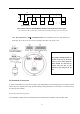
Setting up the Dome Camera 1. Connection of the System There are many ways to wire up a PTZ system. If you have read the introduction at the beginning of these instructions you should have got a good idea what your options are. Below is a general schematic diagram showing you some of these options.
summer but when winter kicks in and the dome’ s current draw jumps from 400ma to 1.25A, an inadequate power supply or a cable with too much voltage drop may stop the dome from working properly.
The PTZ605 convention: series adopts the following RS485 ORANGE = RS485 + or A YELLOW = RS485 –or B You should initially be wiring the dome to the keyboard or DVR on your workshop bench or at least your kitchen table to prove you know how to get everything to work. Once you have done this, it is just a job of extending the cables and physically installing the domes on site.
If you use cores from two different pairs in the CAT5 cable you will not get the benefit of the shielding effect of the cable twists and the dome will function erratically. You must always use a core from a PAIR, not two cores from two different pairs!! Connecting the video out of the dome. The dome has a short BNC lead attached to it, this is the lead that carries the video signal from the built-in camera. You need to extend this lead to the “VIDEO-IN” of the DVR or monitor.
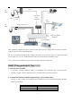
24V AC INPUT RS485 RS485 - ‘B’ CAT5 Data cable RG59 Video Cable Power Cable + ‘A’ RS485 PSU DVR 17 INPUT ON
If you’re using more than one dome on a site Each dome has a unique “address”so that if you are using more than one on a site the keyboard “talks”to the right dome when you want it to PTZ. If you only have the one dome on the site then the default “address”of “1”is okay and you have no reason to change the dome from this. Special Note: With multiple dome sites you need to set up each dome address separately. The following diagram shows the switch options. SW2 sets up the protocol.
Dome Address 1 2 3 4 5 6 7 8 9 10 11 12 13 14 15 16 17 18 DIP-1 ON OFF ON OFF ON OFF ON OFF ON OFF ON OFF ON OFF ON OFF ON OFF DIP-2 OFF ON ON OFF OFF ON ON OFF OFF ON ON OFF OFF ON ON OFF OFF ON DIP-3 OFF OFF OFF ON ON ON ON OFF OFF OFF OFF ON ON ON ON OFF OFF OFF DIP-4 OFF OFF OFF OFF OFF OFF OFF ON ON ON ON ON ON ON ON OFF OFF OFF … 1023 … ON … ON … ON … ON ID-CODE Status DIP-5 DIP-6 DIP-7 OFF OFF OFF OFF OFF OFF OFF OFF OFF OFF OFF OFF OFF OFF OFF OFF OFF OFF OFF OFF OFF OFF OFF OFF OFF OFF OF
Some protocols and the states of the coding switches of normal baud rates of these protocols are shown as follows: ON B01NEO 9600Bps N/ 9600Bps ON 1 2 3 4 5 PANASONI C/ 9600Bps 6 ON PELCO-P/D PELCO- D/2400Bps 2400Bps 2 3 4 5 KALATEL/ 4800Bps 6 OO NN 3 4 5 6 1 2 3 4 5 6 1 2 3 4 5 6 1 2 3 4 5 6 ON 11 22 33 4 4 5 ALEC/ 9600Bps 6 ON PELCO-MK 4800 BPS PELCO- P/ 9600Bps 2 ON 1 PELCO-P/D 4800Bps PELCO- P/ 4800Bps 1 ON 1 2 3 4 5 Ul t r ak/ 9600Bps 6 Setup
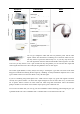
Using the PTZ730 keypad with the excelPTZ series NOTE 1: For more detailed instructions in setting up the keypad or using one of our other keypads, please refer to the instruction manual supplied with the product. PTZ730 keypad NOTE 2: The PTZ730 keypad requires you to press the function key first followed by the value e.g 01 whereas some keypads e.g PTZ700 require the value first, then the function e.
dipswitches on the rear of the unit. Note that all PTZ domes controlled by this keypad must have identical protocol and baud rate settings. The manual supplied with the keypad will show you what these settings should be. Next connect the RS485 connections from the dome/s ensuring that the A and B lines are connected correctly. Finally connect the power supply. Both the PTZ730 and PTZ700 keypads require a 12V DC PSU (500mA minimum). It is recommended to use a POW800 for this purpose.
PRESETS and other functions. The dome has up to 128 presets that once programmed with stay in the domes non-volatile memory so they will be retained even after a power cut. What is a preset? A preset is a particular area or object that the dome was looking at and has been stored into its memory so when the preset is “called-up”the dome will select the area again without the operator using the joystick to do this. Even the zoom at the time is stored into the preset.
Patrols (Tours) –How to set them up and use them A patrol (tour) is simply a collection of at least three preset camera locations that are run in sequence with the dome stopping at each location for a brief period of time and then moving on to the next preset. For example, you could use a patrol so that an outside dome camera points at a gate, then at a side doorway, then zooms out to get an overall shot of a car park and finally zooming in on a delivery bay, before repeating the whole cycle again.
Setting the Patrol (Tour) To setup the patrol/tour you need to enter the Advanced Menu System by selecting 95 on the keypad or 64 . (Call varies according module type) You will see the Main Menu displayed on the screen. Enter the password to enter the menu. The Default is 111111. See Advance Setup menu to change. Using the joystick up/down direction movement, select the MOTION SETUP menu. Use the joystick pan right movement to enter this menu.
Now exit the menu by moving the Joystick down, selecting EXIT and then moving the Joystick to the right to return to the Main Menu. Again use the Joystick to select EXIT and exit the Advanced Menu System by selecting the right pan movement. Calling the Patrol (Tour) There are two methods of initiating the patrol or tour. If you enter 91 via the keypad you can initiate patrol/tour sequence 1 only. You may also initiate a patrol or tour through the Advanced Menu System.
AUTO SCAN- How to set it up Auto-scan scans between two points. These are not presets as per the patrol(tour) facility but auto scan selection points. You may program up to 3 auto scans. STEP 1 – Select the required camera by pressing the button and then entering on the keypad. To setup the Auto Scan you need to enter the Menu System by selecting 95 or 64 on the keypad. Enter the password to enter the menu. The Default password is 111111.
In the AUTO SCAN menu select RUN SCAN. If the start position is the same as the end position it will do a 360° scan. Now press the CLOSE button to save and initiate the Auto Scan. TIP - To stop the scan just move the joystick slightly. RECORD PATTERN- What is a record pattern This dome has an option to store a record pattern. A record pattern consists of a continuous sequence of standard pan and tilt movements or lens commands recorded within a 200 second interval. A record pattern does not use presets.
System by selecting 95 or 64 on the keypad. Enter the password to enter the menu. The Default password is 111111. See Advance Setup menu to change. You will see the Main Menu displayed on the screen. Using the joystick up/down direction movement, select the MOTION SETUP menu. Use the joystick pan right movement to enter this menu. STEP 1 - In the PATTERNS menu select PATTERN NUMBER and enter number from 1 ~3 . Now select RECORD PATTERN.
USING THE DOME’S ADVANCED FUNCTIONS- On Screen Graphics (OSD) – The PTZ605 series boasts six patrol (tour) options, an auto scan option and a record pattern option. All these can be configured using the OSD. To bring up the camera menu press 95 or 64 (varies with module type). Note that entering Preset 01 twice within 4 seconds will also open the menu. Enter the password to enter the menu. The Default password is 111111. See Advance Setup menu to change.
THE MENU SYSTEM Tt Using the Menu System. This menu system allows the user to alter the dome menu instruction options and settings using a control keypad. This first page shows the initial main menu page and only describes the general functions. The following pages show the main menu option selected on the left hand side of the page and a breakdown of that menu page on the right hand side of the page.
To access System Setup press the OPEN button on keypad or move the Joystick to the right. The menu below will be displayed. MAIN MENU 1. 2. 3. 4. 5. 6. 7. 8. SYSTEM SETUP DISPLAY SETUP CAMERA SETUP MOTION SETUP PRIVACY MASK ADVANCE SETUP SYSTEM RESET EXIT 1. 2. 3. 4. 5. 6. SYSTEM SETUP SYSTEM INFORMATION AUTO FLIP OFF PROP PAN SPD OFF RESERVED N/A RETURN SYSTEM INFORMATION This displays system information.
Move the Joystick down to select Display Setup and press the OPEN button or move the Joystick to the right. The menu below will be displayed. MAIN MENU 1. 2. 3. 4. 5. 6. 7. 8.
Move the Joystick down to select Camera Setup and press the OPEN button or move the Joystick to the right. The menu below will be displayed. MAIN MENU 1. 2. 3. 4. 5. 6. 7. 8. SYSTEM SETUP DISPLAY SETUP CAMERA SETUP MOTION SETUP PRIVACY MASK ADVANCE SETUP SYSTEM RESET EXIT CAMERA SETUP D-ZOOM OFF DISPLAY ON FOCUS MODE MANUAL ICR AUTO BLC ON L-SYNC N/A SLOW SHUTTER ON RETURN NOTE: The following camera setup options depend on the camera type installed.
White Balance Mode/Automatic Exposure. WB/AE SETUP AE MODE MANUAL/AUTO/SHUTTER SHUTTER WB MODE AUTO R GAIN B GAIN WDR MODE ON / OFF RETURN AE MODE MANUAL / AUTO / SHUTTER Normally set to AUTO. SHUTTER On available if AE MODE is set to SHUTTER WB MODE ATW / MANUAL / AUTO / INDOOR / OUTDOOR / ONEPUSH This option is used to set White Balance mode. Normally set to AUTO. R GAIN Only available for pulsing red when WB MODE set to MANUAL.
Move the Joystick down to select Motion Setup and press the OPEN button or move the Joystick to the right. The menu below will be displayed. MAIN MENU 1. 2. 3. 4. 5. 6. 7. 8. MOTION SETUP (1) (2) (3) (4) (5) EDIT DOME LABEL RETURN SYSTEM SETUP DISPLAY SETUP CAMERA SETUP MOTION SETUP PRIVACY MASK ADVANCE SETUP SYSTEM RESET EXIT PRESETS PRESET NO. EDIT LABEL CLR LABEL RETURN (1) Enter the preset menu.
SET START LIMIT To set the start position enter this menu item and then move the joystick to position the camera at the starting position and then press CLOSE to save the start position. SET END LIMIT To set the end position select this menu item and then move the joystick to position the camera at the end position and then press CLOSE to save the end position. RUN SCAN To run a scan first set the start and end position. Note that if the start and end position are the same the dome will scan 360 degrees.
RUN PATROL Click on this menu item and then press CLOSE to start patrol. CLEAR PATROL Click to clear a patrol. RETURN Returns to MOTION SETUP menu. (4) Allows recording of a pattern for up to 200 seconds. Up to 3 patterns can be recorded. RECORD PATTERN Click on this menu item to start pattern recording and when complete press CLOSE to save. PATTERNS PATTERN NO. RECORD PATTERN RUN PATTERN CLEAR PATTERN RETURN 001 RUN PATTERN Start the run of a pattern and exit from the menu.
MAIN MENU 1. 2. 3. 4. 5. 6. 7. 8. PRIVACY MASK SYSTEM SETUP DISPLAY SETUP CAMERA SETUP MOTION SETUP PRIVACY MASK ADVANCE SETUP SYSTEM RESET EXIT PRIVACY MASK MASK SHADE DISPLAY EDIT MASK RETURN PRIVACY MASK 01 ~ 04 Up to 4 privacy mask areas to be set according to camera options available. MASK SHADE This allows the colour of the mask area to be set. DISPLAY ON / OFF This option can switch on or off the privacy mask function EDIT MASK This option allows editing of the mask area.
ADVANCE SETUP MAIN MENU 1. 2. 3. 4. 5. 6. 7. 8. SYSTEM SETUP DISPLAY SETUP CAMERA SETUP MOTION SETUP PRIVACY MASK ADVANCE SETUP SYSTEM RESET EXIT (1) This option must not be confused with the Alarm function that can be set with different timing settings. AUTO HOME ON / OFF If the AUTO HOME is set to ON the dome camera will revert to the home position without any action in the PARK TIME.
ADVANCE SETUP MAIN MENU 1. 2. 3. 4. 5. 6. 7. 8. SYSTEM SETUP DISPLAY SETUP CAMERA SETUP MOTION SETUP PRIVACY MASK ADVANCE SETUP SYSTEM RESET EXIT (1) (2) (3) (4) LANGUAGE SET NORTH POSITION RETURN PASSWORD (2) This option allows password protection. ENG PASSWORD PASSWORD ON MODIFY KEY ****** CONFIRM KEY ****** RETURN PASSWORD ON / OFF If this is set to ON password protection is Initiated.
ADVANCE SETUP MAIN MENU 1. 2. 3. 4. 5. 6. 7. 8. SYSTEM SETUP DISPLAY SETUP CAMERA SETUP MOTION SETUP PRIVACY MASK ADVANCE SETUP SYSTEM RESET EXIT (1) (2) (3) (4) LANGUAGE SET NORTH POSITION RETURN CAM ID SETUP (3) This enters the software ID settings menu CAM ID SETUP CAMERA S/N: INPUT S/N: OLD ID NEW ID SAVE & RETURN CANCEL & RETURN CAMERA S/N: Displays the dome series number INPUT S/N: Inputs the dome series number.
ADVANCE SETUP MAIN MENU 1. 2. 3. 4. 5. 6. 7. 8. SYSTEM SETUP DISPLAY SETUP CAMERA SETUP MOTION SETUP PRIVACY MASK ADVANCE SETUP SYSTEM RESET EXIT (1) (2) (3) (4) LANGUAGE SET NORTH POSITION RETURN FAN CONTROL (4) To set the fan control menu settings. ENG FAN CONTROL FAN OPEN TEMP: TEMP DISPLAY RETURN FAN ON / OFF / AUTO The fan working conditions can be set. Setting to ON will set fan running and OFF will switch fan off.
MAIN MENU 1. 2. 3. 4. 5. 6. 7. 8. SYSTEM SETUP DISPLAY SETUP CAMERA SETUP MOTION SETUP PRIVACY MASK ADVANCE SETUP SYSTEM RESET EXIT SYSTEM RESET Selecting this option resets the PTZ menu. The dome will undertake a self test after it undertakes the reset. The following functions are reset: Auto Flip on, PTZ SPD Rate on, ID Display on, Angle Display off, Dome Label Display Off, D-Zoom Off, PT Interlock – AF Auto, BLC off, Auto Home off, Park Time 4 mins, Fan Auto, Temp Display off. EXIT Exit the main menu.
Controlling one camera then another. If you look at the image of the LCD display you can see the CAM=001 indicates that the keyboard is ready to talk to camera with address 1. In the dome the address 1 is set as default in the factory. You need to alter the DIPswitches within the domes to address 2, 3 etc if you have multiple domes on the same site, refer to the previous instructions how to set the DIP Switches. If you have another dome set at camera address 2, press CAM followed by 2.
System Installation Type of Installation a) Wall Installation 128 130 104 103. 4 298 189. 2 190 164 345 347. 6 9 152 205 236 Figure 1 b) Ceiling Installation 470 624 7 152 156 205 236 Figure 2 c) Indoor Ceiling Installation (Figure 3) Indoor Embedded Installation (Figure 4) 156 137 205 125 140 1.
2. Installation Procedure (using wall installation as an example) Preparation before installation --- Dome settings a) Turn the dome cover anti-clockwise (Figure 5) and remove it (Figure 6). open Figure 5 Figure 6 b) Set the dome protocol, baud rate and address as per earlier instructions. c) Refit the dome cover.
Installation of the bracket a) Make four M8 holes in the wall, and put the four M8 bolts into the holes as Figure 8. b) Make a hole at the center of the four holes to connect the cable of the bracket as Figure 8. c) Put the bracket on the wall and tight the four M8 screws as Figure 9. Figure 8 Figure 9 d) Match the “ ”of the bracket A to the “ ”of the dome B as Figure 10. e) Push the dome up and turn anti-clockwise as Figure 11.
f) Lock the housing as Figure 12. g) Fit the dome retaining screws as Figure 13.
Indoor Ceiling Installation a) Install the pedestal on the base plate (as Figure 15). Figure 15 Figure 16 c) Fix the pedestal assembly on the ceiling (Figure 16). d) Match the “MARK”on the ball with the notch on the pedestal, push the ball upward to the end and rotate clockwise until it clicks (as shown in Figure 17). e) Fit the decoration ceiling ring by rotating it clockwise until it is tight (Figure 17). f) Figure 18 shows the unit installed.
Indoor embedded installation Note: To fit this dome into a ceiling, the thickness of the ceiling must be less than 1.65 inches (4.2 cm) but thicker than 0.38 inches (0. 8cm). The ceiling must withstand 4 times the load of the dome weight. a) Cut out the ceiling template supplied as per figure 19 and mark the centre point of the dome position on the ceiling. Figure 19 b) Using the red spot to centre the template draw around the shape as per Figure 20.
c) Cut out the ceiling material using an appropriate cutting tool (Figure 21) Figure 21 d) Fit the “installation pedestal”with the embedded mount (Figure 22) Pedestal Q1A: M4× 12 count er sunk head scr ew ( 3 pcs) Figure 22 e) For easy installation, adjust the three swing mounting clips so that the distance between the clips and the flange is a little longer than ceiling thickness. f) Now swing the three mounting clips flat against the body of the unit and locate the body into the ceiling void.
I ndoor dr op cel i ng i nst al l at i on br acket Swi ng mount i ng Cl i p Cei l i ng Fl ange Decoration Ring Figure 23 Alarm Input cable connections: 1 Figure 24 RED( ORANGE( YELLOW( GREEN( BLAC RED1 : K( WHI TE( ORANGE 2 :BLUE( PI NK( YELLOW 3 GREEN 4 BLACK 5 WHITE 6 BLUE 7 PINK 8 : : : : : : ) 1 ALARM- 1 I N( ) 2 ALARM- 2 I N( ) 3 ALARM- 3 I N( ) 4 ALARM- 4 I N( ) 5ALARM-1 ALM I N C OM( IN ) 6 ALARM OUT COM( )7 ALARM NIN O OUT( ALARM-2 ) 8 ALARM NC OUT( ALARM-3 IN ALARM-4 IN ALARM IN COMMON AL
Note: The alarm input must be a zero volt switch. Any voltage signals will damage the dome. When multiple alarm signals are triggered the dome will respond to them, one by one, and the response time interval will be 2 seconds. When more than one alarm signal is received, the dome will not respond to “line scanning”, “tracking”and “self-learning” functions.
Connecting the Input Alarm devices You will need to decide how many alarm channels will be utilised. For each alarm channel you will need a pair of cable connections and it is recommended that a CAT5 twisted pair be utilised. Connect one core to the selected input alarm channel and the other to the ground (GND) connection. The ground is a common connection for all four alarm channels. At the alarm end connect to the alarm device. This must be a 0 volt switch and maybe for example a door switch.
Connecting the Output Alarm In addition to the alarm inputs, this dome will activate an alarm output if an alarm input is triggered. There are two connections for the alarm output, a common and either a normally open or a normally closed connection. Again this is a 0 volt switch and could be used for example to close a circuit to an audible alarm, lighting or other warning devices. Ensure that the switch line does not carry any voltage.
Appendix A: Lightning Proof and Surge Signal Proof This product adopts TVS lightning proof technology to prevent damage by a lightning strike below 1500 W and surge impulse signals. However it is also necessary to ensure that the following precautions are taken to ensure electrical safety: l Keep the communication cables at least 50 meters away from high voltage equipment or cables. l Where possible locate outdoor cables under eaves to provide best protection.
Appendix B: General Information The Cleaning of Clear Dome Cover To obtain constant clear images, the user should clean the dome cover periodically. l Be very careful when cleaning. Hold the dome cover ring only to avoid touching the acrylic dome cover. The acid from fingerprints will corrode the coating and any scratches on the dome cover may cause distorted or poor images. l Use a soft dry cloth or a similar to clean the inner and outer surfaces. l For more stubborn contamination, use a neutral detergent.