
Manual


1-800-346-6091
11-11-10
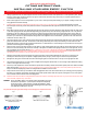
Belled out surface might look
smooth but uneven
Good flat machined surface
How to get it right the rst time...
FITTING INSTRUCTIONS:
INSTALLING YOUR NEW EXEDY CLUTCH
Failure to observe these instructions when tting your Exedy Clutch will void any warranty.
1. Getting it right the rst time. It is vital to diagnose the cause of clutch malfunction before clutch replacement, i.e. check hydraulic system - bearing
free travel - clutch cable, oil leaks and check for any signs of red dust when old clutch is being removed. Any or all of these problems must be
corrected before installing a new clutch.
2. Ensure clutch supplied is correct for the application. If you’re unsure, consult your Exedy Clutch Catalog or your supplier, as tting a clutch to the
wrong application will void the warranty.
3. Flywheel must be replaced or machined as shown below (Fig 2. max 0.03 in.) or warranty will be void and check spigot bearing or the pilot
bush and replace if necessary. Please note pilot bush noises are more apparent when the engine and transmission systems are cold (i.e. in the
mornings).
4. Before tting, check the clutch for any shipping damage. Next clean the gear box main drive shaft splines, then check that clutch disc slides freely
on the shaft. Lightly grease the shaft splines with high melting point grease. Always ensure bell housing is degreased and is free of any dust and
that bers from the worn clutch are removed. If the clutch is a large size pull type clutch check the ID of the bearing head for correct spline size
before installation. Lack of lubrication/dry splines will cause failure to disengage gears and also cause clutch drag. Never over lubricate / grease
the spline of your clutch disc as grease will splatter during rotation of the engine and clutch. Contamination – grease/oil on the clutch disc friction
material will cause the clutch to slip.
5. Check clutch release fork for cracks, check the clutch cable for stretch signs and check the release bearing guide tube for any wear. Always lightly
grease the outside diameter of the tube. This will allow smooth sliding of the bearing carrier. Always check bearing on clutch release fork after
installing the bearing on it. Move the fork forwards and backwards i.e. in both directions, to ensure bearing is secure and does not fall on any part
(clutch fork or bell housing) before retting gear box.
6. Place the clutch cover pressure plate assembly over the clutch disc, after checking that the disc is the right way around and the hub section of the
disc does not fall on the casting of the clutch cover assembly or the ywheel. A suitable clutch aligning tool will ensure correct alignment, assist in
ease of installation and avoid spline damage. (Burrs on splines are a major cause of difcult gear disengagement). Ensure pressure plate dowels
are aligned to the cover. Tighten bolts in a diagonal pattern and never use air tools to install a clutch cover assembly. Torquing down bolts in an
uneven pattern in some instances could cause the lever strut to dislodge itself from the pressure plate casting.
7. When the pressure plate has been torqued down securely to the ywheel, ensure that the diaphragm tips (in the case of a lever type cover
assembly, the release lever tips) are in a parallel or slightly upward position (see Fig 3) and do not go over center of the parallel position.
8. Ret gear box, taking care not to bend the clutch disc. Never hang the gear box off the clutch disc or use any force to align gear box shaft.
9. Check all bell housing dowels are in correct position and tighten bell housing bolts. Ensure there is no dirt or foreign material between the mating
surfaces of the engine and the bell housing.
10. Perform any clutch adjustments to vehicle manufacturer’s specications and always reset the clutch master cylinder push rod to obtain comfortable
pedal release position (clutch taking up as close as possible to the oor prevents clutch shudder and in most cases preferred by vehicle drivers).
Keep in mind that the diaphragm tip position has changed with the installation of the new clutch.
11. Always check the clutch cable if you are unable to obtain disengagement when a new clutch is tted. Start off your checking process by replacing
the cable. If it is a hydraulic clutch start by checking the clutch master cylinder and the clutch slave cylinder, ensuring there is no air in the system.
This is essential to obtain maximum travel for disengagement.
12. Road test vehicle and never abuse a newly tted clutch. Allow 750 mi break in and always adjust free travel on your new clutch at 750 mi and 1500
miles. Thereafter, adjust at every 10,000 miles.
WARNING: Do not use EXEDY clutches in any situation where engine RPM’s may exceed
manufacturer’s specications - a pressure plate could explode unexpectedly
causing serious injury or death to vehicle occupants and bystanders. Clutch
cover and bell housing will not protect against exploding pressure plates. Refer
to the Application Catalogue for correct t.
For performance/sport applications always use an Exedy sports replacement clutch.
Fig 2Fig 1
Fig 3
A = NO GO
B = OK
C = NO GO
OK