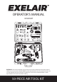
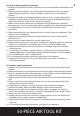
OPERATOR’S MANUAL EX5005KIT SPORTS NEEDLES PLUGS SAFETY NOZZLE TAPERED NOZZLE RUBBER NOZZLE GRINDING STONES WRENCHES TAPE SEAL BITS OIL BOTTLE 50-PSI GAUGE 1/2” 7/16” BITS HOLDER 3/8” TO 1/2” ADAPTOR DUAL TIRE CHUCK EXTENSION BAR CHISELS 1” 7/8” 11/16” 9/16” HAMMER IMPACT BLOW GUN DIE GRINDER RATCHET WARNING! Some dust created by using power tools contains chemicals known to the state of California to cause cancer and birth defects or other reproductive harm.
TABLE OF CONTENTS GENERAL SAFETY RULES.........................................................................................2 AIR SUPPLY..................................................................................................................5 PRODUCT DESCIPTION..............................................................................................7 TECHNICAL SPECIFICATIONS.................................................................................10 ASSEMBLY...........................
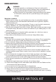
GENERAL SAFETY RULES WARNING! ● Improper operation or maintenance of this tool could result in personal injury and/or property damage. Read and understand all warnings and operation instructions before using this tool. ● When using this tool, these basic safety precautions should always be followed to reduce the risk of personal injury and/or property damage. Workplace conditons 1. Always work in a clean, dry, well-ventilated area free of combustible materials.
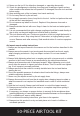
14. Never use the tool if it is defective, damaged, or operating abnormally. 15. Check for misalignment or binding of moving parts, breakage of parts and any other condition that affects the tool operation. If damaged, have the tool serviced before using. 16. Keep working parts of the tool away from hands and body. 17. Do not carry the tool by the air hose. 18. Do not apply excessive force of any kind to the tool. Let the tool perform the work at the rate as it was designed. 19.
Air ratchet wrench safety instructions 1. Always use the ratchet wrench in the manner and for the functions described in this manual. 2. Always ensure the wrench is not moving and disconnected from the air supply when changing sockets etc. Only use impact sockets. Do not use standard sockets. 3. Always finish tightening threaded fasteners, bolts or nuts, or engine parts with a calibrated torque wrench by hand to the correct torque as recommended by the manufacturer where critical torque values are required.
13. Always store this product in a dry and safe place out of reach of children or untrained operators. Air die grinder safety instructions 1. Always use the die grinder in the manner and for the functions described in this manual. 2. Always ensure the grinder is not moving and disconnected from the air supply when changing grinding stones etc. 3. Only use qualified grinding stones. Never use chipped or cracked grinding stones. 4.
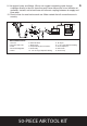
9. Use proper hoses and fittings. We do not suggest connecting quick change couplings directly to the tool since they may cause failure due to tool vibration at operation. Instead, add a lead hose and connect coupling between air supply and hose whip. 10. Check hoses for wear before each use. Make certain that all connections are in security. 12 13 4 1 11 3 2 6 5 10 8 7 AIR SYSTEM LAYOUT: 1. Air Tool 2. Air Hose 3/8" (I.D.) 3. Oiler 4. Pressure Regulator 5. Filter 15 14 9 6. Shut Off Valve 7.
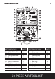
PRODUCT DESCRIPTION 7 V S R T U I J N PLUGS X H P SPORTS NEEDLES W G Q SAFETY NOZZLE TAPERED NOZZLE RUBBER NOZZLE GRINDING STONES WRENCHES TAPE SEAL BITS OIL BOTTLE 50-PSI GAUGE 1/2” 7/16” BITS HOLDER 3/8” TO 1/2” ADAPTOR DUAL TIRE CHUCK EXTENSION BAR CHISELS 1” 7/8” 11/16” 9/16” O Y L M K C F A HAMMER IMPACT E BLOW GUN DIE GRINDER D RATCHET B Z PART A B C D E F G H I J K L M QUANTITY DESCRIPTION 1 1/2" Air Impact Wrench 1 3/8" Air Ratchet Wrench 1 Air Hammer 1 1
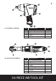
8 A1 B1 D1 C1 E1 1/2" AIR IMPACT WRENCH C2 PART A1 B1 C1 D1 E1 F2 QUANTITY 1 1 1 1 1 DESCRIPTION 1/2" Air Impact Wrench Anvil Trigger Switch Air Inlet A2 H2 G2 E2 D2 B2 3/8" AIR RATCHET WRENCH PART A2 B2 C2 D2 E2 F2 G2 H2 DESCRIPTION 3/8" Air Ratchet Wrench Anvil F/R Knob Trigger Air Regulator Exhaust Deflector Air Inlet Steel Ball Indicator 50-PIECE AIR TOOL KIT QUANTITY 1 1 1 1 1 1 1 1
D3 9 A3 C3 B3 AIR HAMMER PART A3 B3 C3 D3 QUANTITY 1 1 1 1 DESCRIPTION Air Hammer Air Inlet Trigger Cylinder F4 E4 H4 I4 D4 J4 B4 1/4" AIR DIE GRINDER C4 A4 PART A4 B4 C4 D4 E4 F4 G4 H4 I4 J4 G4 DESCRIPTION 1/4" Air Die Grinder Collet Jacket Collet Holder Collet Trigger Lever Air Regulator Exhaust Deflector Steel Ball Indicator Air Inlet 50-PIECE AIR TOOL KIT QUANTITY 1 1 1 1 1 1 1 1 1 1
10 TECHNICAL SPECIFICATIONS 1/2" AIR IMPACT WRENCH COMPONENT Square drive Maximum no load speed Maximum torque Air inlet Air hose (inner diameter) Average air consumption Working pressure SPECIFICATIONS 1/2" 7,200rpm 350Ft-Lb (475Nm) 1/4" NPT 3/8" 6cfm 90psi (6.3bar) 3/8" AIR RATCHET WRENCH COMPONENT Square drive Maximum no load speed Maximum torque Air inlet Air hose (inner diameter) Average air consumption Working pressure SPECIFICATIONS 3/8" 160rpm 60Ft-Lb (85Nm) 1/4" NPT 3/8" 4cfm 90psi (6.
ASSEMBLY 1/2" AIR IMPACT WRENCH 11 1 1. Remove the air inlet protective cap from the air inlet (E1). (See Figure 1) E1 2. Mount a male plug by hand into the air inlet (E1). (See Figure 2) 2 NOTE: Use thread sealant tape on the male plug and tighten it with a wrench for airtight connection. Do not overtighten. 3. Place 2 - 3 drops of air tool oil into the male plug before each use.
4. Choose the correct impact socket (J) as needed and mount it onto the anvil (B1). (See Figure 4) WARNING! Only use impact sockets that have a RPM and Torque rating equal to or greater than the tool itself. 5. If necessary, use the 1/2" extension bar (G) and then mount impact socket onto the bar. (See Figure 5) 12 4 J B1 5 G J 6. Connect air supply hose to the male plug. (See Figure 6) 6 7. Set the working pressure at 90psi/6.3bar for best tool performance.
3/8" AIR RATCHET WRENCH 1. Remove the air inlet protective cap from the air inlet (G2). (See Figure 7) 13 7 G2 2. Mount the male plug by hand into the air inlet (G2). (See Figure 8) 8 NOTE: Use thread sealant tape on the male plug and tighten it with a wrench for airtight connection. Do not overtighten. 3. Place 2 - 3 drops of air tool oil into the male plug before each use.
4. Choose the correct impact socket (J) as needed and mount it onto the anvil (H2). (See Figure 10) WARNING! Only use impact sockets that have a RPM and Torque rating equal to or greater than the tool itself. 5. Connect air supply hose to the male plug. (See Figure 11) 14 10 J B2 11 6. Set the working pressure at 90psi/6.3bar for best tool performance. NOTE: Working pressure refers to the air line pressure set to tool when tool is under working conditions. AIR HAMMER 1.
2. Mount the male plug by hand into the air inlet (B3). (See Figure 13) 15 13 NOTE: Use thread sealant tape on the male plug and tighten it with a wrench for airtight connection. Do not overtighten. 3. Place 2 - 3 drops of air tool oil into the male plug before each use. (See Figure 14) 4. Insert a chisel (K) into the opening of cylinder (D3).
5. Screw the spring retainer (F) onto the cylinder (D3) and firmly secure it. (See Figure 16) 16 16 D3 F 6. Connect air supply hose to the male plug. (See Figure 17) 17 7. Set the working pressure at 90psi/6.3bar for best tool performance. NOTE: Working pressure refers to the air line pressure set to tool when tool is under working conditions. 1/4" AIR DIE GRINDER 1. Remove the air inlet protective cap from the air inlet (J4).
2. Mount a male plug by hand into the air inlet (J4). (See Figure 19) 17 19 NOTE: Use thread sealant tape on the male plug and tighten it with a wrench for airtight connection. Do not overtighten. 3. Place 2 - 3 drops of air tool oil into the male plug before each use. (See Figure 20) 4. Loosen the collet jacket (B4) counterclockwise by hand or with the large wrench while holding the small wrench on the flats of the collet holder (C4).
5. Insert a grinding stone (P) into the collet (D4). (See Figure 22) 22 18 P D4 6. Tighten the collet jacket (B4) clockwise with large wrench while holding the small wrench on the flats of the collet holder (C4). Make sure that the grinding stone is installed securely and tightly. (See Figure 23) 23 B4 I WARNING! Only use grinding accessories that have a RPM and Torque rating equal to or greater than the tool itself. 7. Connect air supply hose to the male plug. (See Figure 24) C4 24 8.
OPERATION 1/2" AIR IMPACT WRENCH 1. How to install/tighten threaded fasteners. Push the switch (D1) forward and have the arrow on the switch (D1) pointing at either of the settings 1, 2, 3 as shown. Press the trigger (C1). The tool anvil (B1) runs clockwise. (See Figure 25) 2. How to remove/loosen threaded fasteners. Push the switch (D1) backward and have the arrow on the switch (D1) pointing at “R” position as shown. Press the trigger (C1). The tool anvil (B1) runs counterclockwise.
3/8" AIR RATCHET WRENCH 1. How to install/tighten threaded fasteners. Turn the F/R knob (C2) counterclockwise to “F” position (F=Forward or Tighten). Press the trigger (D2). The tool anvil (B2) runs clockwise. (See Figure 28) 28 20 C2 B2 D2 2. How to remove/loosen threaded fasteners. Turn the F/R knob (C2) clockwise to “R” position (R=Reverse or Loosen). Press the trigger (D2). The tool anvil (B2) runs counterclockwise.
NOTE: This tool features an exhaust deflector (F2) 9 which can be rotated to any position to direct air away from workpiece or operator. (See Figure 31) 21 31 F2 AIR HAMMER 1. Hold the tool firmly with both hands. Bring the tool towards the workpiece at an angle of 60-70 degrees approximately. 32 2. Press the trigger (C3) slowly with the chisel in light contact with the workpiece. (See Figure 32) 3. Slowly move the chisel across the workpiece surface.
NOTE: This tool features a power regulator valve. Rotate the air regulator (G4) until desired output is achieved. The settings 1, 2, 3, 4 are only for reference and do not denote a specific power output. “Setting 1” (one-line symbol) is the lowest speed while “Setting 4” (four-line symbol) is the highest speed. Rotate the air regulator (G4) until the desired setting is lined up with the small steel ball (I4) on air inlet (J4).
TROUBLESHOOTING PROBLEM Tool runs slowly or will not operate POSSIBLE CAUSE 1. Grit or gum in tool. CORRECTIVE ACTION 1. Flush the tool with air-tool oil or gum solvent. 2. Lubricate the tool. 2. No oil in tool. 3. a. Adjust the regulator on the tool to 3. Low air pressure. maximum setting. b. Adjust the compressor regulator to tool maximum of 90 PSI/6.3 BAR. 4. Tighten and seal hose fittings if leaks are 4. Air hose leaks. found. Use sealing tape. 5. a. Be sure the hose is the proper size. 5.
EXPLODED DIAGRAM AND PARTS LIST 1/2" AIR IMPACT WRENCH 8 9 24 7 10 14 16 20 19 18 7 15 11 1 12 17 13 5 2 3 5 23 4 21 22 24 40 41 6 30 29 34 6 25 37 35 38 36 26 31 28 Part No. 1 2 3 4 5 6 7 8 9 10 11 12 13 14 15 16 17 18 19 20 21 Description Housing* Bushing* Anvil* Hammer cage* Hammer* Hammer pin* Bearing* Oil seal* Front plate* Cylinder * Set pin* Set pin* Rotor* Rotor blade - EX1235IW-14 Rear plate* Gasket* Ring* Rear cover* Washer* Screw* Trigger* 27 32 33 39 Qty.
EXPLODED DIAGRAM AND PARTS LIST 25 33 3/8" AIR RATCHET WRENCH 35 34 6 36 5 37 19 38 27 39 29 40 1 30 41 28 31 42 32 20 3 21 44 24 43 23 22 2 7 4 26 45 46 25 47 48 49 52 16 53 14 50 54 55 51 8 Description Part No.
26 EXPLODED DIAGRAM AND PARTS LIST AIR HAMMER 10 11 28 2 9 8 4 22 1 7 3 5 6 27 17 16 15 14 13 12 18 26 21 19 24 20 25 22 23 Part No. 1 2 3 4 5 6 7 8 9 10 11 12 13 14 Description Housing* Housing cover* Screw* End cover* Valve seat - EX0445AH1-05 Valve - EX0445AH1-06 End cap - EX0445AH1-07 Washer* Piston* Cylinder * Spring retainer* Trigger sleeve* Spring* O-ring - EX0445AH1-14 Qty. 1 1 1 1 1 1 1 1 1 1 1 1 1 1 Part No.
27 EXPLODED DIAGRAM AND PARTS LIST 1/4" AIR DIE GRINDER 41 40 39 38 3 37 28 4 2 36 6 30 34 35 28 33 32 18 31 29 19 20 21 22 1 27 42 5 26 43 23 14 25 15 24 16 17 7 10 17 8 9 11 12 13 Part No.
28 MILTON INDUSTRIES AIR TOOL WARRANTY POLICY 3 YEAR LIMITED WARRANTY Please visit www.miltonindustries.com to register this product for the 3-Year limited warranty offered by Milton. To make any warranty claims or to learn more about the 3 year warranty please visit www.miltonindustries.com For questions about our warranty on this product, contact us at: MILTON INDUSTRIES, INC. 4500 W. CORTLAND STREET, CHICAGO, IL 60639 Phone: 855-G04-MILT (855-464-6458) www.exel-air.