INDOOR TRAINING BIKE OWNER’S MANUAL Item #1230
TABLE OF CONTENTS SERVICE ------------------------------------------------------------------------ 2 WARNING LABEL PLACEMENT ------------------------------------------ 3 PRODUCT SAFETY ---------------------------------------------------------- 4 OVERVIEW DRAWING ------------------------------------------------------ 5 PART LIST ----------------------------------------------------------------------- 6 HARDWARE PACKING LIST & TOOL -----------------------------------ASSEMBLY ----------------------------------
SERVICE IMPORTANT: FOR NORTH AMERICA ONLY To request product service and order replacement parts, please call our customer service department at: 1-866-924-1688 Monday through Friday, 8:00 AM-5:00 PM Pacific Standard Time, or email us at: service@paradigmhw.com Please visit our website at www.paradigmhw.com.
WARNING LABEL PLACEMENT 3
PRODUCT SAFETY Basic precautions should always be followed, including the following safety instructions when using this equipment. Read all instructions before using this equipment. 1. Read all the instructions in this manual and do warm up exercises before using this equipment. 2. Before exercising and to avoid injuring your muscles, perform warm-up exercise for each muscle group is highly recommended. Please refer to Warm Up section of the Owner’s Manual. 3.
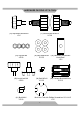
OVERVIEW DRAWING 5
PART LIST No. Description 001 Handlebar End Cap (Ø25.4x2.0) Qty No. Description Qty 6 029 Transport Wheel (Ø64x24) 2 002 Handlebar Foam Grip Ø33xØ23x290 2 030 Nylon Nut M8 2 003 Handlebar Foam Grip Ø33xØ23x220 2 031 Front Stabilizer (80x40x1.
PART LIST No. Description Qty No. Description Qty 057 Nut M5 2 074 Inner Chain Cover 1 058 Brake Plate (140x25x13) 1 075 Axle Ø20x135 1 059 Spring Plate 1 076 Chain 1 060 Bolt M6x12 2 077 Bolt M5x8 1 061 Cap Nut M10x1.0 2 078 Outer Chain Cover 1 062 Spring Washer Ø10 2 079 Flywheel Sleeve (Ø14x1.5x12.5) 1 063 Eyebolt M6 2 080 Nut M10x1.0x5.7mm 3 064 Screw ST4.
HARDWARE PACKING LIST & TOOL (13) Adjustment Knob M10 1 PC (17) Round Knob M16x1.
ASSEMBLY Tool: Multi Hex Tool with Phillips Screwdriver S13-14-15 1. Front and Rear Stabilizers Installation Position the Front Stabilizer (31) in front of the Main Frame (18) and align bolt holes. Attach the Front Stabilizer (31) onto the front curve of the Main Frame (18) with two M8 Cap Nuts (19), two Ø8 Big Washers (20), and two M8x55 mm Carriage Bolts (40). Tighten cap nuts with the Multi Hex Tool with Phillips Screwdriver provided.
ASSEMBLY 2. Seat Post Installation Insert the Seat Post (14) into the Bushing (16) on the tube of the Main Frame (18) and then attach the Round Knob (17) onto the tube of the Main Frame (18) by turning it in a clockwise direction to lock the Seat Post (14) in the suitable position. NOTE: When adjusting the height of seat post, the STOP line cannot be higher than the edge of bushing.
ASSEMBLY Tool: Multi Hex Tool with Phillips Screwdriver S13-14-15 3. Seat Cushion Installation Loosen nuts from underside of the Seat Cushion (9) with the Multi Hex Tool with Phillips Screwdriver provided. Then install the Seat Cushion (9) onto the Seat Sliding Tube (11) and secure with nuts that were loosened. Tighten nuts with the Multi Hex Tool with Phillips Screwdriver provided.
ASSEMBLY 4. Handlebar Post Installation Insert the Handlebar Post (24) into the Bushing (16) on the tube of the Main Frame (18) and then attach the Round Knob (17) onto the tube of the Main Frame (18) by turning it in a clockwise direction to lock the Handlebar Post (24) in the suitable position. NOTE: When adjusting the height of seat post, the STOP line cannot be higher than the edge of bushing.
ASSEMBLY 5. Handlebar Installation Attach the Handlebar (6) onto the Handlebar Post (24) with one Handlebar Adjustment Knob Plate (25) and M10 Adjustment Knob (13). Turn the M10 Adjustment Knob (13) in a clockwise direction to lock the Handlebar (6) in the suitable position.
ASSEMBLY Tool: Multi Hex Tool with Phillips Screwdriver S13-14-15 6. Water Bottle Holder Installation Attach the Water Bottle Holder (33) onto the Main Frame (18) with two M5x16 Bolts (34). Tighten bolts with the Multi Hex Tool with Phillips Screwdriver provided. Install the Water Bottle (32) into the Water Bottle Holder (33).
ASSEMBLY Tool: Multi Hex Tool with Phillips Screwdriver S13-14-15 7. Foot Pedals Installation The Cranks, Pedal Shafts, and Foot Pedals are marked “R” for Right and “L” for Left. Insert the pedal shaft of Left Foot Pedal (15) into threaded hole in the Left Crank (38). Turn the pedal shaft by hand in the counter-clockwise direction until snug. Note: DO NOT turn left foot pedal shaft in the clockwise direction, doing so will strip the threads.
ASSEMBLY Tool: Multi Hex Tool with Phillips Screwdriver S13-14-15 8. Computer Installation Attach the Computer Bracket (43) onto the Handlebar (6) with two M6x6 Bolts (41). Tighten bolts with the Multi Hex Tool with Phillips Screwdriver provided. Remove two M6x15 Bolts (44) from the back of the Computer (42). Remove bolts with the Multi Hex Tool with Phillips Screwdriver provided. Attach the Computer (42) onto the Computer Bracket (43) with two M6x15 Bolts (44) that were removed.
COMPUTER POWER ON 1. Plug in the power supply or press the RESET key for 2 seconds to start the console. LCD will display all segments for 2 seconds (FIGURE 1) with a beep sound. The flywheel dia. “78.0” will display in the DISTANCE column (FIGURE 2) and the LCD will display current temperature, date and time. FIGURE 1 FIGURE 2 2. Use the SET key to adjust TIME, DISTANCE, and CALORIES when setting and press the MODE key after value’s determined. Press the RESET key clear all pre-set values.
COMPUTER 2-2 When a RPM signal is detected, the icon will disappear and the icon will light up (FIGURE 3-4). When a pre-set value reaches to zero, console system will have beep sound as a reminder. 2-3 The icon will show 3 seconds after no RPM signal’s detected. FIGURE 3 FIGURE 4 3. RECOVERY MODE: 3-1 RECOVERY function is only valid when there’s a heart rate input’s detected.
COMPUTER 4. 5. Computer system will wake up if there’s any signal input detected (or press any key). Computer system will switch to power save mode if there’s no signal input detected for more than 4 minutes. Reboot the computer and all pre-set and exercise values will be saved. HOW TO INSTALL THE BATTERIES: 1. Remove the battery cover on the back of the computer. 2. Place two "SIZE-AAA" batteries into the battery housing. 3.
ADJUSTMENTS Adjustable Leveler Adjusting the Adjustable Leveler Turn the Adjustable Leveler on the front and rear stabilizers as needed to level the bike. Brake Knob Adjusting the Brake Knob To increase the load, turn the Brake Knob in a clockwise direction. To decrease the load, turn the Brake Knob in a counterclockwise direction.
ADJUSTMENTS Round Knob Lock Knob Adjusting the Handlebar Height Loosen the Lock Knob and then loosen the Round Knob by turning counterclockwise direction until it can be pulled out. Pull out the Round Knob and then slide the Handlebar Post up or down direction to the suitable position. Lock the Handlebar Post in place by releasing the Round Knob and sliding the Handlebar Post up or down slightly until the Round Knob "pops" down into the locked position.
ADJUSTMENTS Lock Nut Adjusting the Left/Right Elbow Protective Pads Loosen the Lock Nut by turning counterclockwise direction. Slide the Left/Right Elbow Protective Pad right or left direction to the suitable position. Lock the Elbow Protective Pad in place by turning clockwise direction. Lock Knob Round Knob Adjusting the Seat Height Loosen the Lock Knob and then loosen the Round Knob by turning counterclockwise direction until it can be pulled out.
EMERGENCY STOP Adjustment Knob Adjusting the Seat Forward or Back Loosen the Adjustment Knob by turning counterclockwise direction. Slide the Seat Sliding Tube forth or back direction to the suitable position. Lock the Seat Sliding Tube in place by turning clockwise direction. EMERGENCY STOP To emergency stop, press firmly down onto the BRAKE KNOB. Continue holding the BRAKE KNOB down until the flywheel comes to a complete stop.
MOVING THE BIKE Start by carefully pushing down on the handlebar until the rear end of the bike lifts in the air. Carefully push the bike to the desired location.
TROUBLE SHOOTING & MAINTENCE TROUBLE SHOOTING PROBLEM: The training bike wobbles when in use. SOLUTION: Turn the adjustable leveler on the front and rear stabilizers as needed to level the training bike. PROBLEM: There is no display on the computer console. SOLUTION: Verify the extension sensor wire is properly connected to the wire that comes from the computer. SOLUTION: Check if the batteries are correctly positioned and battery springs are in proper contact with batteries.
WARM UP Quadriceps Stretch With one hand against a wall for balance, reach behind you and pull your right foot up. Bring your heel as close to your buttocks as possible. Hold for 15 counts and repeat with left foot up. Inner Thigh Stretch Sit with the soles of your feet together with your knees pointing outward. Pull your feet as close to your groin as possible. Gently push your knees towards the floor and hold for 15 counts.
WARRANTY Paradigm Health & Wellness, Inc. warrants to the original purchaser that this product is free from defects in material and workmanship when used for the purpose intended, under the conditions that it has been installed and operated in according to Paradigm Health & Wellness, Inc.’s Owner’s Manual. Paradigm Health & Wellness, Inc.’s obligation under this warranty is limited to replacing free of charge, any parts which may prove to be defective under normal home use.
FAX FORM Paradigm Health & Wellness, Inc. PARTS REQUEST FAX FORM Please fax this form to (1-626-810-2166) OR YOU CAN EMAIL CUSTOMER SERVICE REQUESTS TO service@paradigmhw.