User Guide AXS-100 Series OTDR
Copyright © 2007–2010 EXFO Inc. All rights reserved. No part of this publication may be reproduced, stored in a retrieval system or transmitted in any form, be it electronically, mechanically, or by any other means such as photocopying, recording or otherwise, without the prior written permission of EXFO Inc. (EXFO). Information provided by EXFO is believed to be accurate and reliable.
Contents Contents Certification Information ...................................................................................................... vii 1 Introducing the AXS-100 Series OTDR ......................................................... 1 Main Features .........................................................................................................................1 Power Sources ..............................................................................................................
Contents 6 Testing Fibers ..............................................................................................37 Testing in Auto Mode ...........................................................................................................38 Testing in Fault Finder Mode ................................................................................................42 Testing in Manual (Advanced) Mode .....................................................................................
Contents 12 Testing Network Connections ................................................................... 95 Performing a Ping Test ..........................................................................................................95 Performing a Trace Route Test ...............................................................................................97 Setting Storage Parameters for Ping Tests .............................................................................
Contents B Description of Event Types ......................................................................127 Span Start ..........................................................................................................................127 Span End ...........................................................................................................................127 Continuous Fiber .............................................................................................................
Certification Information Certification Information F.C.C. Information Electronic test equipment is exempt from Part 15 compliance (FCC) in the United States. However, compliance verification tests are systematically performed on most EXFO equipment. Information Electronic test equipment is subject to the EMC Directive in the European Union. The EN61326 standard prescribes both emission and immunity requirements for laboratory, measurement, and control equipment.
Certification Information DECLARATION OF CONFORMITY Application of Council Directives: Manufacturer’s Name: Manufacturer’s Address: Equipment Type/Environment: Trade Name/Model No.: 2006/95/EC - The Low Voltage Directive 2004/108/EC - The EMC Directive 2006/66/EC - The Battery Directive 93/68/EEC - CE Marking And their amendments EXFO Inc.
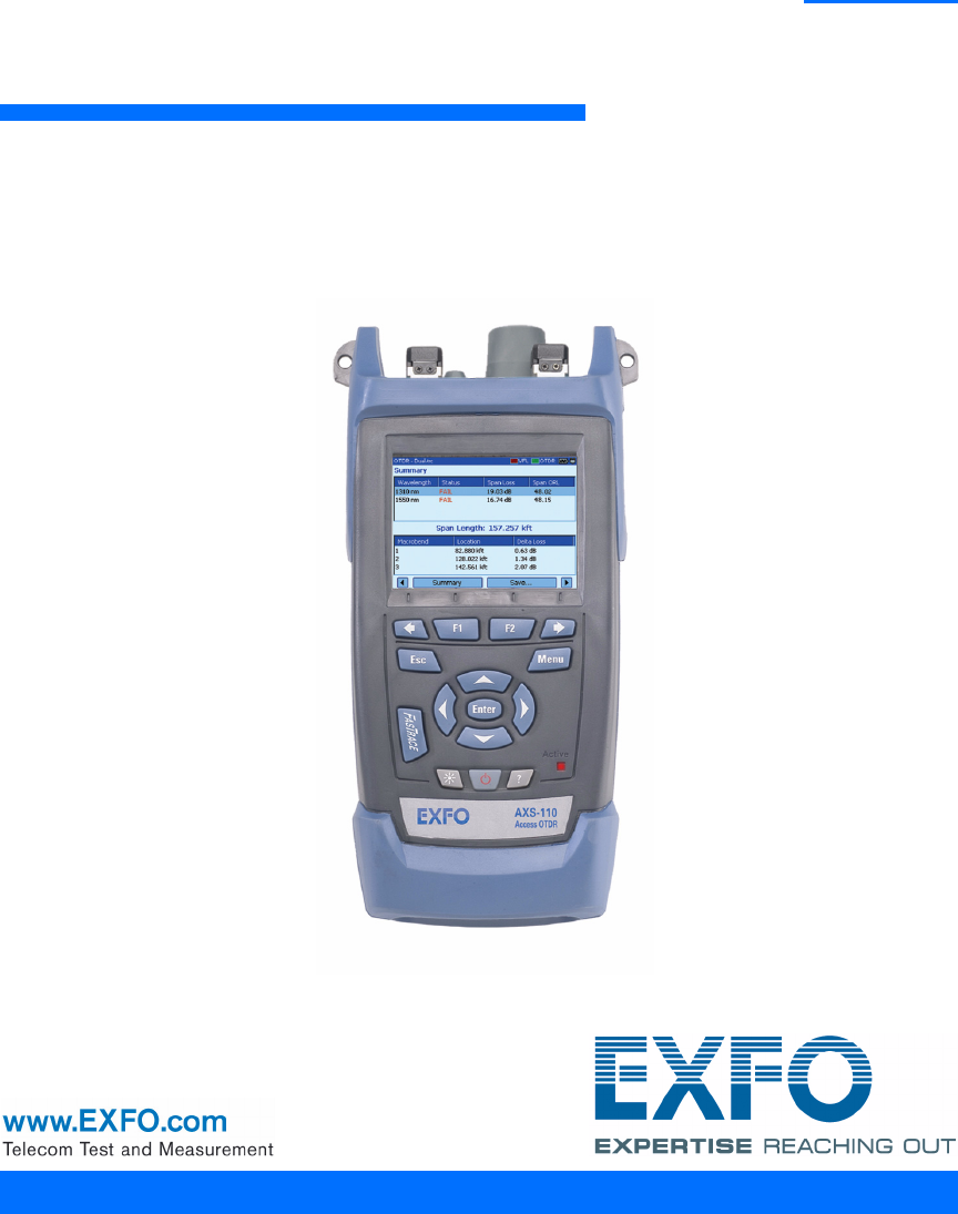
1 Introducing the AXS-100 Series OTDR The AXS-100 Series OTDR is a compact handheld OTDR optimized for access/FTTx network testing. The unit can be equipped with optional power meter, visual fault locator (VFL), and fiber inspection probe.
Introducing the AXS-100 Series OTDR Main Features Visual fault locator port and soft cap Power meter detector port Singlemode OTDR port Infrared port (for printer) On some models only: Singlemode live port for in-service testing OR Multimode OTDR port Inspection probe connector USB host port (for data transfer using memory drive) USB client port (for data transfer via ActiveSync) Note: Ports and connectors on your unit may differ from the illustration.
Introducing the AXS-100 Series OTDR Main Features Other test utilities: ³ Visual fault locator to inspect or identify fibers (optional) ³ Video fiber inspection probe (optional) ³ Power meter (optional) Safety label and serial number (under the stand) Quick reference labels Battery compartment (two rechargeable batteries) OTDR 3
Introducing the AXS-100 Series OTDR Main Features Other useful characteristics: 4 ³ Customizable test thresholds with visual pass/fail analysis ³ Memory for 500 OTDR traces and possible data transfer to a computer ³ Energy-saving features: automatic backlight or unit shutdown ³ Multilingual graphical user interface ³ Comprehensive online help available from each function and Quick Reference labels affixed to back of unit ³ Data post-processing: You can install the OTDR Viewer software (provide
Introducing the AXS-100 Series OTDR Power Sources Power Sources The unit operates with the following power sources: ³ AC adapter/charger (connected to standard power outlet—indoor use only). Compatible car outlet adapter available upon request. ³ Two lithium-ion rechargeable batteries (automatically take over if you disconnect the AC adapter/charger). Battery recharge is automatic when the AC adapter/charger is connected.
Introducing the AXS-100 Series OTDR OTDR Basic Principles OTDR Basic Principles An OTDR sends short pulses of light into a fiber. Light scattering occurs in the fiber due to discontinuities such as connectors, splices, bends, and faults. An OTDR then detects and analyzes the backscattered signals. The signal strength is measured for specific intervals of time and is used to characterize events.
Introducing the AXS-100 Series OTDR OTDR Basic Principles An OTDR uses the effects of Rayleigh scattering and Fresnel reflection to measure the fiber condition, but the Fresnel reflection is tens of thousands of times greater in power level than the backscatter. ³ Rayleigh scattering occurs when a pulse travels down the fiber and small variations in the material, such as variations and discontinuities in the index of refraction, cause light to be scattered in all directions.
Introducing the AXS-100 Series OTDR Conventions Conventions Before using the product described in this manual, you should understand the following conventions: WARNING Indicates a potentially hazardous situation which, if not avoided, could result in death or serious injury. Do not proceed unless you understand and meet the required conditions. CAUTION Indicates a potentially hazardous situation which, if not avoided, may result in minor or moderate injury.
2 Safety Information WARNING Do not install or terminate fibers while a light source is active. Never look directly into a live fiber and ensure that your eyes are protected at all times. WARNING Use of controls, adjustments and procedures for operation and maintenance other than those specified herein may result in hazardous radiation exposure or impair the protection provided by this unit.
Safety Information Laser Safety Information (Units with VFL) Laser Safety Information (Units with VFL) Your instrument is a Class 3R laser product in compliance with standards IEC 60825-1 and 21 CFR 1040.10. It is potentially harmful in direct intrabeam viewing. The following label(s) indicate that the product contains a Class 3R source: Affixed to back (under the stand) Indicated on connector panel Electrical Safety Information The AC adapter/charger provided with this unit (14.
3 Getting Started with Your OTDR Turning the Unit On and Off When you turn the unit on, you may use it immediately under normal conditions. When the unit is turned off, it keeps the following parameters in its internal memory: ³ Test parameters ³ User-defined thresholds ³ Regional, LCD, and energy-saving settings ³ Saved test results IMPORTANT If you remove batteries (and the AC adapter/charger is disconnected), the unit will turn off without saving the above elements.
Getting Started with Your OTDR Turning the Unit On and Off There are two ways to turn off the AXS-100 Series OTDR ³ Suspend: the next time you turn your unit on, you will quickly return to your work environment. ³ Shutdown: completely cuts power to the unit; the unit will perform a complete restart routine the next time you use it. You should perform a shutdown if you do not intend to use your unit for a week or more. To turn the unit on: Press .
Getting Started with Your OTDR Using Menus and Keypad Using Menus and Keypad You can access optical tools from the keypad or menu. Menu options may differ depending on your unit configuration. Status Bar Utility name (OTDR, File Manager, VFL, etc.
Getting Started with Your OTDR Using Menus and Keypad Keypad To activate the function displayed directly above To scroll through available functions To cancel/exit current function To access the main menu To move around, select items, and change parameters To start (or stop) an acquisition To adjust brightness (four levels) To turn unit on/off To access help about current function To access main features: 1. Press the Menu key. 2. Use the arrows to select a feature and press Enter.
4 Customizing Your OTDR Selecting the Distance Units There are three distance units available: meters, miles, and kilofeet. Note: The attenuation values are always expressed in dBs per kilometer. To select distance units: 1. Press Menu, select Setup > Unit, and then press Enter. 2. Use the left/right function arrows until you see Regional Settings, and then press F2 to display the pane. 3. Press Enter to open the Distance unit list. 4.
Customizing Your OTDR Selecting the Language of Operation Selecting the Language of Operation You may display the user interface in one of the available languages (default is English). If other languages become available in the future, you could access them by replacing the unit software (see Upgrading the AXS-100 Series OTDR Software on page 108). Values are kept in memory when you turn the unit off. To select a new interface language: 1. Press Menu, select Setup > Unit, and then press Enter. 2.
Customizing Your OTDR Setting the Date and Time Setting the Date and Time When saving results, the unit also saves the corresponding date and time. You must enter the date according to the year-month-day format and the time according to the 24-hour format. You can also modify the time zone. To set the date and time: 1. Press Menu, select Setup > Unit, and then press Enter. 2. Use the left/right function arrows until you see Regional Settings, and then display the pane (F1/F2 key). 3.
Customizing Your OTDR Adjusting the Brightness Adjusting the Brightness To fit your work environment, you may adjust the LCD brightness. Values are kept in memory when you turn the unit off. To adjust the display brightness: Press the key repeatedly to switch between brightness levels (0-3-6-9). OR 1. Press Menu, select Setup > Unit, and then press Enter. 2. If necessary, use the left/right function arrows until you see General, and then display the pane (F1/F2 key).
Customizing Your OTDR Selecting a Printer Selecting a Printer To print reports, you must configure the printer first. Your unit supports the Printek 2” printer only and communicates with it via the infrared port located on the top panel. If you want to print on a network printer or if you want to print other type of reports, you must transfer the desired files on a computer on which ToolBox 6 (or later), FastReporter or OTDR Viewer is installed. To select a printer: 1.
Customizing Your OTDR Configuring the Power Management Settings Configuring the Power Management Settings When you do not use the unit for a while, the display may be dimmed to save power. You can set idle durations for AC adapter/charger and battery operation. The unit goes in suspend mode after the specified duration has expired (see Turning the Unit On and Off on page 11). Values are kept in memory when you turn the unit off. Note: When the backlight is dimmed, the unit operation is not interrupted.
5 Setting Up Your OTDR Installing the EXFO Universal Interface (EUI) The EUIfixed baseplate is available for connectors with angled (APC) or non-angled (UPC) polishing. A green border around the baseplate indicates that it is for APC-type connectors. Green border indicates APC option Bare metal (or blue border) indicates UPC option To install an EUI connector adapter onto the EUI baseplate: 1. Hold the EUI connector adapter so the dust cap opens downwards. 2 3 4 2.
Setting Up Your OTDR Cleaning and Connecting Optical Fibers Cleaning and Connecting Optical Fibers IMPORTANT To ensure maximum power and to avoid erroneous readings: ³ Always inspect fiber ends and make sure that they are clean as explained below before inserting them into the port. EXFO is not responsible for damage or errors caused by bad fiber cleaning or handling. ³ Ensure that your patchcord has appropriate connectors. Joining mismatched connectors will damage the ferrules.
Setting Up Your OTDR Cleaning and Connecting Optical Fibers 3. Carefully align the connector and port to prevent the fiber end from touching the outside of the port or rubbing against other surfaces. If your connector features a key, ensure that it is fully fitted into the port’s corresponding notch. 4. Push the connector in so that the fiber-optic cable is firmly in place, thus ensuring adequate contact.
Setting General OTDR Parameters Setting General OTDR Parameters You can set preferences such as: ³ Grid: You can display or hide the grid appearing on the graph’s background. By default, the grid is displayed. ³ Zoom and markers: You can display or hide the zoom controls as well as the markers appearing on the graph. ³ Automatic zoom on fiber span: You can set the trace display to show only the portion of the trace that is located between the span start and the span end, in full-trace view.
Setting General OTDR Parameters To set the general OTDR parameters: 1. Press Menu, select Setup > OTDR, and then press Enter. 2. Display the General pane (F1/F2 key). 3. Use the up/down arrows to highlight the desired item, and then press Enter to select it. You can press Enter one more time to clear the boxes. To revert to the factory-default settings: 1. Press Menu, select Setup > OTDR, and then press Enter. 2. From the General pane, use the arrows to select Default, and then press Enter to confirm.
Setting the Acquisition Parameters Setting the Acquisition Parameters You can set parameters such as IOR (group index), backscatter, and helix factor. You can also enable or disable the first connector check. Setting the IOR, Backscatter, and Helix Factor Your unit contains default IOR (group index), backscatter, and helix factor values that you can modify if they do not suit your testing needs.
Setting the Acquisition Parameters To set the IOR, backscatter, and helix factor parameters: 1. Press Menu, select Setup > OTDR, and then press Enter. 2. Display the Acquisition pane (F1/F2 key). 3. Use the up/down arrows to select the wavelength box, and then press Enter to open it. 4. Select the wavelength for which you want to modify parameters. Press Enter to confirm your choice. 5.
Setting the Acquisition Parameters Enabling or Disabling the First Connector Check The first connector check feature is used to verify that the fibers are properly connected to the OTDR. It verifies the injection level and the reflectance of the first connector. It displays a message when a unusually high loss or reflectance occur at the first connection. You enable or disable this feature for all wavelengths at a time. To enable or disable the first connector check: 1.
Setting Analysis Parameters Setting Analysis Parameters ³ To define the actual fiber span start, you can set the launch fiber length. When you perform tests with your unit, you connect a launch fiber between your unit and the fiber under test. This is why, by default, the fiber span includes the launch fiber. When you define the length of the launch fiber, the application sets the fiber span start at the beginning of the fiber under test.
Setting Analysis Parameters To set analysis parameters: 1. Press Menu, select Setup > OTDR, and then press Enter. 2. Display the Analysis pane (F1/F2 key). 3. Use the arrows to select any of the settings, and then press Enter to display the on-screen keyboard (for details about using keyboards, see Using Menus and Keypad on page 13). 4. Enter the new value and press OK (F1/F2 key). As you enter the value, the application indicates the minimum or maximum value allowed.
Setting Pass/Fail Thresholds Setting Pass/Fail Thresholds Note: This function is available only with the optional FTTx software package. You can enable and set pass/fail threshold parameters for your tests. You can define thresholds to specify acceptable values (in dB) for splice loss, connector loss, reflectance, span loss and span ORL, and this, for each wavelength.
Setting Pass/Fail Thresholds To set pass/fail thresholds: 1. Press Menu, select Setup > OTDR, and then press Enter. 2. Use the left/right function arrows until you see Pass/Fail Thresholds, and then display the pane (F1/F2 key). 3. Press Enter to open the wavelength list. 4. Use the up/down arrows to select the desired wavelength. Press Enter to confirm your choice. 5. Use the up/down arrows to highlight the desired threshold name. If necessary, press Enter to select the check box.
Setting Macrobend Parameters Setting Macrobend Parameters Note: This function is available only with the optional FTTx software package. Your unit can locate macrobends by comparing the loss values measured at a certain location, for a certain wavelength (for example, 1310 nm) with the loss values measured at the corresponding location, but for a greater wavelength (for example, 1550 nm).
Setting Macrobend Parameters To set macrobend parameters: 1. Press Menu, select Setup > OTDR, and then press Enter. 2. Display the Macrobend pane (F1/F2 key). 3. If necessary, press Enter to select the Display macrobend check box. If you clear the check box, the application will not detect macrobends. 4. Press Enter to open the Wavelengths list. 5. Use the up/down arrows to select the desired wavelengths. Press Enter to confirm your choice. 6.
Setting Storage Parameters Setting Storage Parameters Each time you save a trace, the unit suggests a file name based on autonaming settings. After saving a result, the unit prepares the next file name by incrementing the suffix. File names: maximum of 20 characters for prefix and 3 digits for suffix. By default, traces are saved in native (.trc) format, but you can configure your unit to save them in Bellcore (.sor) format. Note: If you select the Bellcore (.
Setting Storage Parameters To set the file format: 1. Press Menu, select Setup > OTDR, and then press Enter. 2. Use the left/right function arrows until you see Storage, and then display the pane (F1/F2 key). 3. Use the arrows to select Default file format, and then press Enter to open the list. 4. Use the up/down arrows to select the desired format, and then press Enter to confirm. To revert to the factory-default for file format and autonaming scheme: 1.
6 Testing Fibers The OTDR offers different test modes: ³ Auto: sets all test parameters, performs tests at the specified wavelengths, and provides complete results. ³ Fault finder: rapidly locates fiber ends and displays length of the fiber under test. This function is available only with the optional FTTx software package. ³ Manual (advanced): offers all the tools you need to perform complete OTDR tests and measurements manually and gives you control over all test parameters.
Testing Fibers Testing in Auto Mode Testing in Auto Mode The application will automatically evaluate the best settings according to the fiber link currently connected to the unit (in less than 5 seconds). By default, fiber characteristics are evaluated each time you start a test. This is particularly useful if you often have to test fiber links of different lengths. If you prefer, you can set your unit to keep the same settings (range and pulse) for all acquisitions.
Testing Fibers Testing in Auto Mode To acquire traces in Auto mode: 1. Clean the connectors properly (see Cleaning and Connecting Optical Fibers on page 22). 2. Connect a launch fiber between the device under test and the OTDR port. If necessary, set the launch fiber length (see Setting Analysis Parameters on page 29).
Testing Fibers Testing in Auto Mode 4. Use the left/right function arrows until you see Parameters, and then display the pane (F1/F2 key). 5. Select the test mode as follows: 5a. Use the arrows to select the OTDR mode list, and then press Enter to open the list. 5b. Use the up/down arrows to select Auto, and then press Enter to confirm. 6. Select test wavelengths as follows: 6a.
Testing Fibers Testing in Auto Mode 8. Specify whether the unit must keep the fiber settings for all acquisitions or not, as follows: 8a. Use the arrows to select the Keep parameters list, and then press Enter to open it. 8b. If you want the unit to reset the settings for each acquisition, select No. OR If you want the unit to always use the same parameters, select Yes. 8c. Press Enter to confirm.
Testing Fibers Testing in Fault Finder Mode Testing in Fault Finder Mode Note: This function is available only with the optional FTTx software package. The application offers you a special testing feature to rapidly locate fiber ends. It also displays the length of the fiber under test. The unit will determine the more appropriate wavelength (singlemode or multimode, depending on your test configuration). Duration of the acquisition is 45 seconds.
Testing Fibers Testing in Fault Finder Mode 4. Use the left/right function arrows until you see Parameters, and then display the pane (F1/F2 key). 5. Select the test mode as follows: 5a. Use the arrows to select the OTDR mode list, and then press Enter to open it. 5b. Use the up/down arrows to select Fault finder, and then press Enter to confirm. 6.
Testing Fibers Testing in Manual (Advanced) Mode Testing in Manual (Advanced) Mode You can set distance range, pulse, and duration of the acquisition in this mode. Note: Not all pulse widths are compatible with all wavelengths. If you intend to test at multimode wavelengths, carefully read Launch Conditions for Multimode Measurements on page 50. To acquire traces in Manual (Advanced) mode: 1. Clean the connectors properly (see Cleaning and Connecting Optical Fibers on page 22). 2.
Testing Fibers Testing in Manual (Advanced) Mode 4. Use the left/right function arrows until you see Parameters, and then display the pane (F1/F2 key). 5. Select the test mode as follows: 5a. Use the arrows to select the OTDR mode list, and then press Enter to open it. 5b. Use the up/down arrows to select Manual, and then press Enter to confirm. 6. Select test wavelengths as follows: 6a.
Testing Fibers Testing in Manual (Advanced) Mode 8. Select pulse as follows: 8a. Use the arrows to select the Pulse list and press Enter to open the list. 8b. Use the up/down arrows to select the desired pulse, and then press Enter. 9. Select duration of the acquisition as follows: 9a. Use the arrows to select the Duration list, and then press Enter to open the list. 9b. Use the up/down arrows to select the desired duration for the acquisition, and then press Enter to confirm. 10.
Testing Fibers Monitoring Fiber in Real Time Mode Monitoring Fiber in Real Time Mode You can monitor fiber at one wavelength at a time. You can also switch from Real time mode to Manual mode at any time. If you intend to test at multimode wavelengths, carefully read Launch Conditions for Multimode Measurements on page 50. To monitor fiber in Real time mode: 1. Clean the connectors properly (see Cleaning and Connecting Optical Fibers on page 22). 2.
Testing Fibers Monitoring Fiber in Real Time Mode 5. Select the test mode as follows: 5a. Use the arrows to select the OTDR mode list and press Enter to open the list. 5b. Use the up/down arrows to select Real time, and then press Enter to confirm. 6. Select test wavelengths as follows: 6a.
Testing Fibers Monitoring Fiber in Real Time Mode 7. Select range as follows: 7a. Use the arrows to select the Range list, and then press Enter to open the list. 7b. Use the up/down arrows to select the desired distance range, and then press Enter to confirm. 8. Select pulse as follows: 8a. Use the arrows to select the Pulse list, and then press Enter to open the list. 8b. Use the up/down arrows to select the desired pulse, and then press Enter to confirm. 9. Press FASTRACE to start the acquisition.
Testing Fibers Launch Conditions for Multimode Measurements Launch Conditions for Multimode Measurements In a multimode fiber network, the attenuation of a signal is highly dependent on the mode distribution (or launch condition) of the source that emits this signal. In the same way, the attenuation reading performed by any test instrument will also depend on the mode distribution of its light source. A single light source cannot be conditioned for both 50 μm (50 MMF) and 62.5 μm (62.
Testing Fibers Launch Conditions for Multimode Measurements The table on fiber types gives information about tests with the 50 μm and 62.5 μm fibers. Fiber type 50 μm Recommended mode filter Perform a five-turn mandrel-wrap (wrapping the patchcord a minimum of five turns around the mandrel tool) on the patchcord connecting the OTDR to the fiber under test. As per FOTP-34: Remarks Nominal launch conditions are overfilled.
7 Managing Test Results There are many ways to view the results: ³ Summary pane ³ Events pane ³ Trace pane ³ Trace Info. (trace information) pane Summary Pane This pane is displayed once the test is complete if you selected the corresponding feature (see Setting General OTDR Parameters on page 24). You can also select Summary (F1/F2 keys).
Managing Test Results Events Pane Events Pane This pane shows the list of events found during the test. You can select Events (F1/F2 keys) to display the pane. Values appearing in white on a red background exceed the defined thresholds. Wavelength of the displayed trace Use left/right arrows to switch between the different wavelengths Event type (see Description of Event Types on page 127) 54 You can select an item with up/down arrows and press Enter to switch to Trace pane.
Managing Test Results Trace Pane Trace Pane You can select Trace (F1/F2 keys) to display the pane. Reflectance and loss values appear in white on a red background when they exceed the defined thresholds.
Managing Test Results Trace Info. Pane Trace Info. Pane After acquiring a trace, you might want to view details about the acquisition. You can also include information about the tested fiber and job or add comments. This information is saved along with the trace. Some of the information is common to all wavelengths (location A and B, cable ID and fiber ID). Some other is specific to the current wavelength (job ID, customer and comments). If you add or delete information from the Trace Info.
Managing Test Results Trace Info. Pane To document results: 1. Once a trace has been acquired or reopened, press Menu, select OTDR, and then press Enter. 2. Use the left/right function arrows until you see Trace Info., then display the pane (F1/F2 key). 3. Use the arrows to select the item to modify. Modifiable items are followed by a keyboard icon. 4. Press Enter to display the on-screen keyboard (for details about using keyboards, see Using Menus and Keypad on page 13). 5.
Managing Test Results Using Markers Using Markers You can use markers (A and B) to view the position and level of an event on a trace. Note: If you do not see the markers on your unit, they are probably hidden (see Setting General OTDR Parameters on page 24). To move a marker: 1. Press Menu, select OTDR, and then press Enter. 2. Use the left/right function arrows until you see Trace, and then display the pane (F1/F2 key). 3. Use Next Marker (F1/F2 key) to select the marker to move. 4.
Managing Test Results Using Zoom Controls Using Zoom Controls As soon as you select one of the zoom controls to change the scale of the graph, a magnifying glass icon appears. When the scale changes, the trace is always centered on the area surrounding the magnifying glass icon. You can let the unit automatically adjust the zoom on the currently selected event or zoom in on or out of the graph using manual zoom. You can also return to the original graph scale.
Managing Test Results Using Zoom Controls To view specific portions of the graph: 1. Press Menu, select OTDR, and then press Enter. 2. Use the left/right function arrows until you see Trace, and then display the pane (F1/F2 key). 3. Display the Manual Zoom pane (F1/F2 key). 4. Use the arrows to move the magnifying glass icon to the area where you want to adjust the zoom. 5. Select the zoom parameters. ³ Press Zoom Mode (F1/F2 key) as many times as needed to select the desired type of zoom.
Managing Test Results Using Zoom Controls To revert to the complete graph view: 1. From the Trace pane, use the left/right function arrows until you see Full Trace. 2. Press Full Trace (F1/F2 key) to revert to complete graph view. Note: If the Automatic zoom on fiber span feature is selected in the OTDR setup, the application will zoom in between span start and span end.
Managing Test Results Printing Test Results Printing Test Results With a Printek 2” printer, you can print results directly from the AXS-100 Series OTDR. Note: You cannot print ping or trace route test results from the AXS-100 Series OTDR. The unit communicates with the printer through its infrared port. To print test results: 1. Select the printer (see Selecting a Printer on page 19). 2. Once a trace has been acquired or reopened, press Menu, select OTDR, and then press Enter. 3. Select Print (F1/F2 key).
Managing Test Results Opening Trace Files Opening Trace Files You can open a maximum of two files at a time: a main trace and a reference trace (if the corresponding feature is selected). Your unit can display traces saved in native (.trc) and Bellcore (.sor) formats. To open trace files: 1. Press Menu, select OTDR, and then press Enter. 2. Use the left/right function arrows until you see Open, then display the pane (F1/F2 key). 3.
Managing Test Results Saving Files Saving Files Each time you save a new file, the unit suggests a file name based on autonaming settings. ³ Trace files: By default, traces are saved in native (.trc) format, but you can configure your unit to save them in Bellcore (.sor) format. For more information on storage settings, see Setting Storage Parameters on page 35. ³ Image files: By default, images are saved in .jpg format, but you can configure your unit to save them in .bmp format.
Managing Test Results Checking Available Memory To save files: 1. Use the left/right function arrows until you see Save, and then display the pane (F1/F2 key). 2. If desired, press New Folder to create folders (for more information, see Creating Folders on page 66). 3. If you want to modify the storage location, proceed as follows: 3a. Press the up arrow to access the file list. 3b. Use the up/down arrows to highlight the desired folder. 3c.
Managing Test Results Creating Folders Creating Folders For easier data management, you can create folders from several panes in the application. If you prefer, you can copy folders instead, see Copying, Renaming, or Deleting Files and Folders on page 67. To create folders: 1. From the current window, select the location where you want to create a folder as follows: 1a. Find the folder or disk: Use the up/down arrows to navigate in the list and the right arrow to open a folder or explore a disk. 1b.
Managing Test Results Copying, Renaming, or Deleting Files and Folders Copying, Renaming, or Deleting Files and Folders You can copy, rename, or delete folders or single files directly from your unit. To copy files: 1. Press Menu, select File Manager/Info. > File Manager, and then press Enter. 2. Select the desired file or folder as follows: 2a. Find the file or folder using the up/down arrows to navigate in the list and the right arrow to open a folder. 2b.
Managing Test Results Copying, Renaming, or Deleting Files and Folders To rename files or folders: 1. Press Menu, select File Manager/Info. > File Manager, and then press Enter. 2. Select the desired file or folder as follows: 2a. Find the file or folder using the up/down arrows to navigate in the list and the right arrow to open a folder. 2b. Highlight the desired file or folder, but do not select it (by pressing Enter). 3. Select Rename (F1/F2 key).
Managing Test Results Copying, Renaming, or Deleting Files and Folders To delete files: 1. Press Menu, select File Manager/Info. > File Manager, and press Enter. 2. Select the file or folder as follows: 2a. Find the file or folder using the up/down arrows to navigate in the list and the right arrow to open a folder. 2b. Highlight the desired file or folder and press Enter to select it. 3. Select Delete Files (F1/F2 key).
Managing Test Results Transferring Results to a Computer Transferring Results to a Computer You can transfer files from your OTDR to a USB memory drive, or a computer. You can also transfer data from a storage device or from a computer to your OTDR. Your OTDR is equipped with two types of USB ports: ³ USB host port (type A connector) to connect USB memory drives ³ USB secondary port (type B connector) to transfer data directly between your OTDR and a computer using a USB cable.
Managing Test Results Transferring Results to a Computer To transfer files or folders between your unit and a USB memory drive: 1. Connect the USB memory drive to the USB host port. 2. Press Menu, select File Manager/Info. > File Manager, and then press Enter. The list of drives and folders should include the memory drive (Removable Disk). You can now manage your files and folders as you wish. Note: You can connect a memory drive even while File Manager is open.
Managing Test Results Transferring Results to a Computer To transfer files or folders between your unit and a computer: IMPORTANT You must install Microsoft ActiveSync on the computer you want to use with your OTDR. Otherwise, you will not be able to transfer data. Before connecting your unit to a computer, you must install the required software on the computer. For more information on the installation, refer to the Release Notes on the installation CD. 1.
Managing Test Results Transferring Results to a Computer 3. Once ActiveSync indicates that the computer and the OTDR are connected, right-click the ActiveSync icon then select Explore to access the files and folders stored on your OTDR. OR On the computer desktop, double-click My Computer. Double-click Mobile Device to access the files and folders stored on your unit. You can now manage your files and folders as you wish. 4.
8 Using Your OTDR as a Light Source You can use your OTDR as a light source. The source signal uses the OTDR ports. This signal can be: ³ continuous (constant power over the temperature range, but about 3 dB lower than maximum) or ³ modulated (270 Hz, 1 kHz or 2 kHz, 270 Hz blink, 1 kHz blink or 2 kHz blink). Note: When you switch wavelengths, the modulation remains the same. WARNING When a source is active, its port emits invisible laser radiation.
Using Your OTDR as a Light Source Activating/Deactivating a Light Source Activating/Deactivating a Light Source The Power Meter pane remains displayed when you use the source. The source status is indicated with a LED in the status bar and with the Active indicator under the keypad. Note: The Active indicator always shows the source, VFL, or OTDR port status (even in FIP or idle mode). To activate the light source: 1.
Using Your OTDR as a Light Source Modulating the Source Signal Modulating the Source Signal When you turn the unit on, the signal is continuous (unmodulated) by default. When you switch wavelengths, the modulation remains the same. Modulation is indicated in the Source pane. Available values are: Continuous, 270 Hz, 1 kHz, 2 kHz, 270 Hz blink, 1 kHz blink, or 2 kHz blink. To change the signal modulation: 1. Activate the source if you want. 2.
9 Measuring Power or Loss The AXS-100 Series OTDR can be equipped with an optional optical power meter to measure absolute power (in dBm or W) or insertion loss (in dB). The power meter port is independent of the OTDR port(s). Power meter port Measured power/loss Open list or press Wavelength to switch between favorite wavelengths. Open list or press W/dBm/dB to display power (W or dBm) or loss (dB). Press Setup to modify the list of favorite wavelengths.
Measuring Power or Loss Defining the List of Favorite Wavelengths Defining the List of Favorite Wavelengths You can put the wavelengths you want to use on a list of favorite wavelengths. Only wavelengths selected from this list are available for measurements. By default, the list contains all the calibrated wavelengths: 850 nm, 1300 nm, 1310 nm, 1490 nm, 1550 nm, 1625 nm, 1650 nm. Note: The list must always contain at least one selected wavelength.
Measuring Power or Loss Setting a Power Correction Factor Setting a Power Correction Factor You may apply a correction factor (CF) to the measured power to compensate for inaccuracies or drifts. You should change the CF after performing an offset nulling.
Measuring Power or Loss Reverting to Factory Settings Reverting to Factory Settings You can revert to factory settings at any time. The following items will be reset: ³ Reference values ³ Nulling values ³ List of favorite wavelengths ³ Correction factors (reset to 1) To revert to the factory-default settings: 1. Press Menu and select Setup > Power Meter, and then press Enter. OR From the Power Meter pane, press Setup (F1/F2 key). 2. Press Factory Settings (F1/F2 key). 3. Answer Yes to confirm.
Measuring Power or Loss Nulling Offsets Nulling Offsets Temperature and humidity variations affect the performance of electronic circuits and optical detectors, which can offset measurement results. To compensate for this offset, the unit is equipped with an offset nulling function. Your unit is designed not to require offset nulling under normal operation, but you should perform it whenever environmental conditions change significantly or when measuring very low power values.
Measuring Power or Loss Referencing Your Power Meter to a Source Referencing Your Power Meter to a Source In reference mode, your unit displays the loss created by the fiber under test only, since it subtracts a reference value from the measured power. In the figure, the reference value (-43.98 dBm) is subtracted from the actual power measured (-37.64 dBm).
Measuring Power or Loss Referencing Your Power Meter to a Source 4. Activate the source at the desired wavelength. 5. Match the power meter wavelength with the source wavelength. Press Wavelength (F1/F2 key) to switch between favorite wavelengths of your power meter (see Defining the List of Favorite Wavelengths on page 80). 6. Press W/dBm/dB (F1/F2 key) until you get dB units to retrieve the last saved reference. OR Press Reference (F1/F2 key) to save the current power as the new reference.
Measuring Power or Loss Measuring Power or Loss Measuring Power or Loss To measure power or loss: 1. If necessary, perform an offset nulling operation (see Nulling Offsets on page 83). 2. Press Menu, select Power Meter, and then press Enter. 3. Clean the connectors properly (see Cleaning and Connecting Optical Fibers on page 22). 4. For loss measurements, reference your power meter to a light source (see Referencing Your Power Meter to a Source on page 84), and then deactivate the light source. 5.
Measuring Power or Loss Measuring Power or Loss 6. Using bulkhead adapters, connect the fiber under test between the reference patchcords (one patchcord is already connected to source and the other is connected to power meter). Adapter Reference patchcord Reference patchcord Bulkhead adapter OUT Fiber under test Light source Bulkhead adapter Power meter 7. Activate the source at the desired wavelength. 8. Match the power meter wavelength with the source wavelength.
10 Identifying Fiber Faults Visually Note: This feature is available only if your unit is equipped with a VFL port. The visual fault locator (VFL) helps you identify bends, faulty connectors, splices and other causes of signal loss. From its dedicated port, the VFL emits a red signal which becomes visible at the location of a fault on the fiber. This signal can be continuous (the default) or blinking (1 Hz). WARNING When the VFL is active, the VFL port emits visible laser radiation.
Identifying Fiber Faults Visually To activate the VFL and inspect a fiber: 1. Connect the fiber under test to the VFL port (see Cleaning and Connecting Optical Fibers on page 22). 2. Press Menu, select VFL, and then press Enter. 3. Press VFL On/Off (F1/F2 key) to activate the VFL (list displays On). OR Use the arrows to open the VFL status list and select On. 4. To switch between blinking (1 Hz) and continuous signals, press Modulation (F1/F2 key).
11 Inspecting Fibers with the FIP The fiber inspection probe (FIP) allows you to find dirty or damaged connectors by displaying an enlarged view of the connector surface. The following common features of video fiber inspection probes are compatible with your unit: ³ Magnification control: supports 200x, 400x, or other zoom factors. ³ Focus control: allows you to fine-tune the display quality. ³ You can save images (in .jpg or .bmp format).
Inspecting Fibers with the FIP Adjusting Brightness and Contrast for the FIP Adjusting Brightness and Contrast for the FIP You can adjust brightness and contrast of the image displayed on screen. 1. Press Menu, select Probe, and press Enter. 2. Select Display Settings (F1/F2 key). 3. Use the up/down arrows to switch between brightness and contrast controls. 4. Use the left/right arrows to adjust level. 5. Confirm new settings with OK (F1 key).
Inspecting Fibers with the FIP Setting Storage Parameters for Images Setting Storage Parameters for Images Each time you save an image, the unit suggests a file name based on autonaming settings. After saving a file, the unit prepares the next file name by incrementing the suffix. File names: maximum 20 characters for prefix, 3 digits for number. By default, traces are saved in .jpg format, but you can configure your unit to save them in .bmp format. To set the probe image autonaming scheme: 1.
12 Testing Network Connections The two most common basic tests widely used in networking are the ping test and the trace route test. With these tests, you can ensure that IP packets travel as expected from a local host to a remote host and vice versa. Performing a Ping Test The ping test is a basic test that measures the average time it takes for a packet to reach the remote host. With this test, you can quickly verify that the remote host functions properly. You can set the URL (IP address).
Testing Network Connections Performing a Ping Test To perform a ping test: 1. Connect the network cable to the RJ-45 port located on the left panel of your unit. 2. Press Menu, select Network Tests > Ping, and then press Enter. 3. Enter the URL or IP address to reach as follows: 3a. Press Enter to open the Address list. 3b. Select an existing URL or IP address.
Testing Network Connections Performing a Trace Route Test Performing a Trace Route Test The trace route test is used to evaluate the average number of nodes that are required to reach the final host. It is often use to troubleshoot networks (identify routing problems or accesses blocked by firewalls). You can enter a remote host address. Other parameters are predefined. To perform a trace route test: 1. Connect the network cable to the RJ-45 port located on the left panel of your unit. 2.
Testing Network Connections Setting Storage Parameters for Ping Tests Setting Storage Parameters for Ping Tests Each time you save ping results, the unit suggests a file name based on autonaming settings. After saving a result, the unit prepares the next file name by incrementing the suffix. File names: maximum 20 characters for prefix, 3 digits for number. Ping results are saved in text (.txt) format. To set the ping autonaming scheme: 1. Press Menu, select Setup > Ping, and then press Enter. 2.
Testing Network Connections Setting Storage Parameters for Trace Route Tests Setting Storage Parameters for Trace Route Tests Each time you save trace route results, the unit suggests a file name based on autonaming settings. After saving a result, the unit prepares the next file name by incrementing the suffix. File names: maximum 20 characters for prefix, 3 digits for number. Trace route results are saved in text (.txt) format. To set the trace route autonaming scheme: 1.
13 Maintenance To help ensure long, trouble-free operation: ³ Always inspect fiber-optic connectors before using them and clean them if necessary. ³ Keep the unit free of dust. ³ Clean the unit casing and front panel with a cloth slightly dampened with water. ³ Store unit at room temperature in a clean and dry area. Keep the unit out of direct sunlight. ³ Avoid high humidity or significant temperature fluctuations. ³ Avoid unnecessary shocks and vibrations.
Maintenance Cleaning EUI Connectors Cleaning EUI Connectors Regular cleaning of EUI connectors will help maintain optimum performance. There is no need to disassemble the unit. IMPORTANT If any damage occurs to internal connectors, the module casing will have to be opened and a new calibration will be required. To clean EUI connectors: 1. Remove the EUI from the instrument to expose the connector baseplate and ferrule. Turn Pull Push 2. Moisten a 2.
Maintenance Cleaning EUI Connectors 5. Repeat steps 3 to 4 with a dry cleaning tip. Note: Make sure you don’t touch the soft end of the cleaning tip. 6. Clean the ferrule in the connector port as follows: 6a. Deposit one drop of isopropyl alcohol on a lint-free wiping cloth. IMPORTANT Isopropyl alcohol may leave residues if used abundantly or left to evaporate (about 10 seconds). Avoid contact between the tip of the bottle and the wiping cloth, and dry the surface quickly. 6b.
Maintenance Cleaning Detector Ports Cleaning Detector Ports Regular cleaning of detectors will help maintain measurement accuracy. IMPORTANT Always cover detectors with protective caps when unit is not in use. To clean detector ports: 1. Remove the protective cap and adapter (FOA) from the detector. 2. If the detector is dusty, blow dry with compressed air. 3. Being careful not to touch the soft end of the swab, moisten a cleaning tip with only one drop of isopropyl alcohol.
Maintenance Recharging Main Batteries Recharging Main Batteries ³ The charge status of both batteries is shown on the Unit Information pane (press Menu, select File Manager/Info. > Information, and then press Enter). ³ The charge status is also indicated by the LEDs on the left side of the unit: Status LED Battery Charge Status Green Fully charged Red Charging Yellow Error IMPORTANT ³ Batteries are not charged at the factory.
Maintenance Replacing Batteries Replacing Batteries As soon as you remove the battery compartment door, the unit will turn itself off. WARNING Do not throw batteries into fire or water and do not short-circuit the batteries’ electrical contact. Do not disassemble. To replace main batteries: 1. Open the battery compartment door located at the back of the unit. 2. Lift the mobile part of the battery lock and turn it 90o clockwise.
Maintenance Recalibrating the Unit Recalibrating the Unit Manufacturing and service center calibrations are based on the ISO/IEC 17025 Standard, which states that calibration documents must not contain a recommended calibration interval, unless this has been previously agreed upon with the customer. Validity of specifications depends on operating conditions.
Maintenance Upgrading the AXS-100 Series OTDR Software Upgrading the AXS-100 Series OTDR Software The necessary software has been preinstalled and configured at the factory. However, you may have to upgrade the software when new versions become available. For the upgrade, you will need: ³ the installation CD (includes ActiveSync installation kit) ³ a computer equipped with a USB port; Windows 2000 or Windows XP must be installed on the computer.
Maintenance Upgrading the AXS-100 Series OTDR Software To upgrade the software: 1. Turn on the computer and insert the installation CD in the CD-ROM drive. 2. Follow the on-screen instructions. All the necessary components, including ActiveSync, will be installed on your computer. 3. Once the installation is complete, turn on the OTDR. 4. Connect the provided USB cable to the computer (type A end) and your OTDR (type B end). ActiveSync automatically opens and establishes the connection. 5.
Maintenance Recycling and Disposal (Applies to European Union Only) Recycling and Disposal (Applies to European Union Only) Recycle or dispose of your product (including electric and electronic accessories) properly, in accordance with local regulations. Do not dispose of it in ordinary garbage receptacles. This equipment was sold after August 13, 2005 (as identified by the black rectangle).
14 Troubleshooting Solving Common Problems The table below presents common problems and their solution. Problem Possible Cause Impossible to turn on unit. ³ You did not press long enough. ³ Main batteries discharged. ³ Battery compartment door is open. Solution ³ Press for 2 seconds. ³ Charge batteries by connecting the AC adapter/charger. ³ Close battery compartment door. ³ One of the two batteries ³ Insert 2 batteries and is missing. replace battery compartment door. ³ Weather too cold.
Troubleshooting Solving Common Problems Problem Possible Cause Solution Light reaches power meter Ensure protective caps are During offset nulling, you tightly screwed on power get the following message: detector. meter port and perform the “Light detected during nulling again. nulling.” Do not use rubber cover. The unit is not responding. Shut down the unit by pressing and holding it down. You will hear a first beep; release the key after you hear a second beep. Turn the unit on again to reset it.
Troubleshooting Solving Common Problems Problem You can no longer view the OTDR application. Possible Cause Solution Shut down the unit by pressing and holding it down. You will hear a first beep; release the key after you hear a second beep. Press simultaneously , Esc, and Menu and hold them a few seconds until you see Maintenance Mode on the screen. It may take a few seconds before the maintenance menu appears. Use the up/down arrows to highlight Restore System Disk, and then press Enter.
Troubleshooting Solving Common Problems Problem Possible Cause The application displays a Light has been detected on message indicating that a the OTDR port during the “live fiber error” occurred. acquisition or while you were monitoring a fiber in real-time mode. Solution Disconnect the fiber from the OTDR port. Press OK to close the message. Start another acquisition without any fiber connected to the OTDR. The message about live fiber error should not appear and the OTDR trace should look “normal”.
Troubleshooting Obtaining Online Help Obtaining Online Help Context-sensitive help is conveniently available at all times to guide you through the use of your unit. To obtain online help about the current function: On the unit keypad, press the ? key. To navigate in the online help: OTDR ³ Use up/down arrows to scroll through help page. ³ Use left/right arrows to switch between hyperlinks (underlined items) and press Enter to link to selected help page.
Troubleshooting Contacting the Technical Support Group Contacting the Technical Support Group To obtain after-sales service or technical support for this product, contact EXFO at one of the following numbers. The Technical Support Group is available to take your calls from Monday to Friday, 8:00 a.m. to 7:00 p.m. (Eastern Time in North America). For detailed information about technical support, visit the EXFO Web site at www.exfo.com.
Troubleshooting Transportation You may also be requested to provide the firmware or software version numbers. To find out the firmware or software version numbers: 1. Press Menu, select File Manager/Info. > Information, and press Enter. 2. Press About (F1/F2 key). Transportation Maintain a temperature range within specifications when transporting the unit. Transportation damage can occur from improper handling.
15 Warranty General Information EXFO Inc. (EXFO) warrants this equipment against defects in material and workmanship for a period of one year from the date of original shipment. EXFO also warrants that this equipment will meet applicable specifications under normal use.
Warranty Liability Liability EXFO shall not be liable for damages resulting from the use of the product, nor shall be responsible for any failure in the performance of other items to which the product is connected or the operation of any system of which the product may be a part. EXFO shall not be liable for damages resulting from improper usage or unauthorized modification of the product, its accompanying accessories and software.
Warranty Exclusions Exclusions EXFO reserves the right to make changes in the design or construction of any of its products at any time without incurring obligation to make any changes whatsoever on units purchased. Accessories, including but not limited to fuses, pilot lamps, batteries and universal interfaces (EUI) used with EXFO products are not covered by this warranty.
Warranty Service and Repairs Service and Repairs EXFO commits to providing product service and repair for five years following the date of purchase. To send any equipment for service or repair: 1. Call one of EXFO’s authorized service centers (see EXFO Service Centers Worldwide on page 123). Support personnel will determine if the equipment requires service, repair, or calibration. 2.
Warranty EXFO Service Centers Worldwide EXFO Service Centers Worldwide If your product requires servicing, contact your nearest authorized service center. EXFO Headquarters Service Center 400 Godin Avenue Quebec (Quebec) G1M 2K2 CANADA EXFO Europe Service Center Omega Enterprise Park, Electron Way Chandlers Ford, Hampshire S053 4SE ENGLAND EXFO Telecom Equipment (Shenzhen) Ltd. 3rd Floor, Building 10, Yu Sheng Industrial Park (Gu Shu Crossing), No.
A Technical Specifications IMPORTANT The following technical specifications can change without notice. The information presented in this section is provided as a reference only. To obtain this product’s most recent technical specifications, visit the EXFO Web site at www.exfo.com.
Technical Specifications 126 AXS-100 Series
B Description of Event Types This section describes all types of events that may appear in the events table generated by the application. Here is a guide to the descriptions: ³ Each type of event has its own symbol. ³ Each type of event is represented by a graph of a fiber trace, which illustrates the power reflected back toward the source as a function of distance. ³ An arrow points to the location of the event type in the trace.
Description of Event Types Continuous Fiber Continuous Fiber Reflected power (dB) Continuous fiber Distance (km) This event indicates that the selected acquisition range was shorter than the fiber length. 128 ³ The fiber end was not detected because the analysis process ended before reaching the end of the fiber. ³ The acquisition distance range should therefore be increased to a value greater than the fiber length. ³ There is no loss or reflectance specified for continuous fiber events.
Description of Event Types End of Analysis End of Analysis Reflected power (dB) Distance (km) This event indicates that the pulse width used did not provide enough dynamic range to get to the end of the fiber. OTDR ³ The analysis ended before reaching the end of the fiber because the signal-to-noise ratio was too low. ³ The pulse width should therefore be increased so the signal reaches the end of the fiber with a sufficient signal-to-noise ratio.
Description of Event Types Non-Reflective Event Non-Reflective Event Reflected power (dB) Non-reflective event Linear downward slope due to Rayleigh backscatter Distance (km) This event is characterized by a sudden decrease in the Rayleigh backscatter signal level. It appears as a discontinuity in the downward slope of the trace signal. 130 ³ This event is often caused by splices, macrobends, or microbends in the fiber. ³ A loss value is specified for non-reflective events.
Description of Event Types Positive Event Positive Event Reflected power (dB) Positive event Distance (km) This event indicates a splice with an apparent gain, due to the junction of two fiber sections having different fiber backscatter characteristics (backscatter and backscatter capture coefficients). OTDR ³ A loss value is specified for positive events. The loss specified does not indicate the true loss of the event.
Description of Event Types Launch Level Launch Level Reflected power (dB) Launch level event position Second event Launch level Linear area Distance (km) This event indicates the level of the signal launched into the fiber. ³ The figure above shows how the launch level is measured. A straight line is plotted using least-square approximation to fit all trace points in the linear area between the first and second detected events.
Description of Event Types Fiber Section Fiber Section Reflected power (dB) Fiber section Fiber section Distance (km) This symbol denotes a fiber section with no event. OTDR ³ The sum of all fiber sections contained in an entire fiber trace equals the total fiber length. Detected events are distinct—even if they cover more than one point on the trace. ³ A loss value is specified for fiber section events. No reflectance is specified for this type of event.
Description of Event Types Reflective Event (Possible Echo) Reflective Event (Possible Echo) Reflected power (dB) OTDR connector Second connector Third connector Reflective event (possible echo) Distance (km) This symbol indicates a reflective event that can be a real reflection or an echo produced by another stronger reflection located closer to the source. ³ In the example above, the launched pulse hits the third connector, is reflected back to the OTDR and reflected again into the fiber.
Description of Event Types Echo Echo Reflected power (dB) OTDR connector Second connector End connector Echo Lightwave travel Distance (km) This symbol indicates that an echo has been detected after the end of the fiber. OTDR ³ In the example above, the launched pulse travels up to the end connector and is reflected back toward the OTDR. Then, it reaches the second connector and is reflected again toward the end connector. It is then reflected back to the OTDR.
Description of Event Types Merged Reflective Event Merged Reflective Event Reflected power (dB) Reflective events Point A Point B Total loss (Δ dB) Merged Reflective event position Distance (km) This symbol denotes a reflective event combined with one or more other reflective events. It also indicates the total loss produced by the merged reflective events following it in the events table. 136 ³ A Merged Reflective Event is composed of reflective events.
Description of Event Types Merged Reflective Event ³ OTDR The total loss (Δ dB) produced by the events is measured by plotting two straight lines. ³ The first line is plotted by fitting, through least-square approximation, trace points in the linear area preceding the first event. ³ The second line is plotted by fitting, through least-square approximation, trace points in the linear area following the second event.
Description of Event Types Reflective Event Reflective Event Reflected power (dB) Clipped level Reflective events Distance (km) Reflective faults appear as spikes in the fiber trace. They are caused by an abrupt discontinuity in the index of refraction. 138 ³ Reflective events cause a significant portion of the energy initially launched into the fiber to be reflected back toward the source.
Index Index A AC adapter/charger ................................. 5, 10 acquisition Auto mode ............................................ 39 Fault finder mode .................................. 42 Manual mode ........................................ 44 Real time mode...................................... 47 starting .................................................. 14 viewing details....................................... 56 adding folders .............................................
Index deleting files................................................ 67 description event types .......................................... 127 power meter.......................................... 79 detection thresholds end of fiber............................................ 29 reflectance............................................. 29 reverting to default ............................... 30 splice loss .............................................. 29 detector performance ...............................
Index H hazard, laser radiation..............................9–10 helix factor definition ............................................... 26 reverting to default................................ 28 help. see online help high loss, identifying ................................... 28 high reflectance, identifying........................ 28 I identification fibers and cables.................................... 35 firmware and software versions........... 117 identification label ...............................
Index N naming image files automatically................ 93 network testing........................................... 95 O offset nulling............................................... 83 on and off, turning unit .............................. 11 online help key for ................................................... 14 obtaining............................................. 115 opening trace files....................................... 63 ORL thresholds ............................................
Index probe autonaming image files ......................... 93 brightness and contrast, adjusting ........ 92 connector ................................................ 2 optional ................................................... 3 using...................................................... 91 product features ................................................... 1 identification label............................... 116 specifications ....................................... 125 protective cap ............
Index Summary pane ...................................... 24, 53 suspend mode............................................. 20 symbols, safety.............................................. 8 system disk, restore................................... 113 T technical specifications ............................. 125 technical support ...................................... 116 temperature for storage............................ 101 test parameters ...........................................
NOTICE 抩⛙ CHINESE REGULATION ON RESTRICTION OF HAZARDOUS SUBSTANCES ₼⦌␂ℝ☀⹂䓸德棟Ⓟ䤓屓⸩ NAMES AND CONTENTS OF THE TOXIC OR HAZARDOUS SUBSTANCES OR ELEMENTS CONTAINED IN THIS EXFO PRODUCT ▔⚺⦷㦻 EXFO ℶ❐₼䤓㦘㹡㦘⹂䓸德㒥⏒侯䤓⚜䱿✛⚺摞 O X Indicates that this toxic or hazardous substance contained in all of the homogeneous materials for this part is below the limit requirement in SJ/T11363-2006 嫷䯉年㦘㹡㦘⹂䓸德⦷年捷ↅ㓏㦘⧖德㧟㠨₼䤓⚺摞⧖⦷ SJ/T11363-2006 㪖屓⸩䤓 棟摞尐㻑ⅴₚᇭ Indicates that this toxic or hazardous substance contained in at least one of the
MARKING REQUIREMENTS 㪖㽷尐㻑 Product Environmental protection use period (years) Logo ℶ❐ 䘾⬒≬㔳∎䞷㦮棟 ( ) 㪖㉦ This Exfo product 㦻 EXFO ℶ❐ Batterya 䟄㻯 a a. If applicable.
P/N: 1059121 www.EXFO.com · info@exfo.com CORPORATE HEADQUARTERS 400 Godin Avenue Quebec (Quebec) G1M 2K2 CANADA Tel.: 1 418 683-0211 · Fax: 1 418 683-2170 EXFO AMERICA 3701 Plano Parkway, Suite 160 Plano TX, 75075 USA Tel.: 1 972 907-1505 · Fax: 1 972 836-0164 EXFO EUROPE Omega Enterprise Park, Electron Way Chandlers Ford, Hampshire S053 4SE ENGLAND Tel.: +44 2380 246810 · Fax: +44 2380 246801 EXFO ASIA-PACIFIC 151 Chin Swee Road #03-29, Manhattan House SINGAPORE 169876 Tel.