
Manual


Table Of Contents
- Certification Information
- 1 Introducing the AXS-100 Series OTDR
- 2 Safety Information
- 3 Getting Started with Your OTDR
- 4 Customizing Your OTDR
- 5 Setting Up Your OTDR
- 6 Testing Fibers
- 7 Managing Test Results
- 8 Using Your OTDR as a Light Source
- 9 Measuring Power or Loss
- 10 Identifying Fiber Faults Visually
- 11 Inspecting Fibers with the FIP
- 12 Testing Network Connections
- 13 Maintenance
- 14 Troubleshooting
- 15 Warranty
- A Technical Specifications
- B Description of Event Types
- Index
Description of Event Types
132 AXS-100 Series
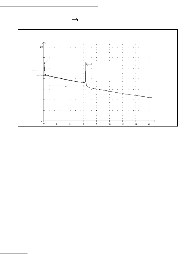
Launch Level
Launch Level
This event indicates the level of the signal launched into the fiber.
³ The figure above shows how the launch level is measured.
A straight line is plotted using least-square approximation to fit all trace
points in the linear area between the first and second detected events.
The straight line is projected toward the Y-axis (dB) until it crosses the
axis.
The crossing point indicates the launch level.
³ <<<< in the events table indicates that the launch level is too low.
Reflected power
(dB)
Distance
(km)
Launch level
event position
Second event
Launch
level
Linear area