
Manual


Table Of Contents
- Certification Information
- 1 Introducing the AXS-100 Series OTDR
- 2 Safety Information
- 3 Getting Started with Your OTDR
- 4 Customizing Your OTDR
- 5 Setting Up Your OTDR
- 6 Testing Fibers
- 7 Managing Test Results
- 8 Using Your OTDR as a Light Source
- 9 Measuring Power or Loss
- 10 Identifying Fiber Faults Visually
- 11 Inspecting Fibers with the FIP
- 12 Testing Network Connections
- 13 Maintenance
- 14 Troubleshooting
- 15 Warranty
- A Technical Specifications
- B Description of Event Types
- Index
Description of Event Types
OTDR 135
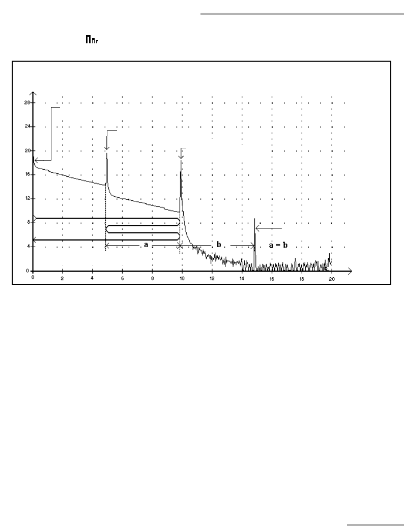
Echo
Echo
This symbol indicates that an echo has been detected after the end of the
fiber.
³ In the example above, the launched pulse travels up to the end
connector and is reflected back toward the OTDR. Then, it reaches the
second connector and is reflected again toward the end connector. It is
then reflected back to the OTDR.
³ The application interprets this new reflection as an echo because of its
characteristics (reflectance and particular position with respect to
other reflections).
³ The distance between the second connector reflection and the end
connector reflection is equal to the distance between the end
connector reflection and the echo.
³ There is no loss specified for echo events.
Reflected power
(dB)
Distance
(km)
OTDR connector
Second connector
End connector
Echo
Lightwave travel