Instruction Manual EX20 SMK Combination Alarm • • • • Photoelectric Smoke Sensing Rate of Rise Temperature Sensing Fixed Temperature Sensing with multiLINX Wireless Connectivity SIGNALING MADE IN THE U.S.A.
Table of Contents About Your New Dual Sensor Photoelectric Smoke Alarm General Information About Your New Dual Detector Smoke Alarm ............ page 3 Thank you for purchasing the Exigent EX20 SMK Smoke Alarm. Smoke alarms play an important role in protecting your family and home from the dangers of fire. Please carefully read and follow the information in this booklet to ensure that your alarms operate properly and are located in the areas best suited for activation. Contents of your Kit .............
Contents of Your Kit Recommended Locations for your Smoke Alarm Please make sure the following is included in your kit: Bedrooms. A major threat from fire occurs at night when people are sleeping. Smoke alarms are required protection in all sleeping rooms. Alarm Plastic Anchors (2) Battery Version 1” Screws (2) Only Instruction Manual Mounting Bracket Hallways. A principal threat to people sleeping in bedrooms comes from fires elsewhere in the home.
Areas Not Appropriate for Smoke Alarms Kitchens. Do not install near kitchen appliances. Steam and by-products of cooking might cause nuisance alarms. National Fire Protection Association Standards This equipment should be installed in accordance with the National Fire Protection Association’s Standard 72 (National Fire Protection Association, Batterymarch Park, Quincy, MA 02269). For your information, the National Fire Protection Association’s Standard 72, 2013 Edition, Section 29.5.
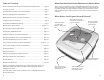
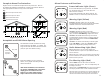
Complete Home Fire Protection Alarm Features and Functions Exigent Sensors recommends complete home fire protection. This can be achieved by installing a combination of smoke, CO and heat alarms in their appropriate locations in every room of the house. Power Indicator Light (Green) On the EX20 SMK (battery-only powered), the POWER icon will briefly flash every 30 seconds when the alarm has been activated.
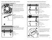
Alarm Features and Functions Deactivating the EX20 SMK Alarm Testing the Alarm When the alarm’s End-of-Life signal occurs, the alarm must be deactivated and disposed of properly. Be sure and have a replacement alarm available. Every alarm should be tested weekly to ensure proper operation. To test the alarm, press and release the button on the front face. lock-out hole slide switch With the pin still pressed firmly in place, slide the switch in the direction indicated by the arrow in the drawing.
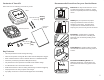
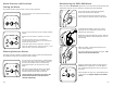
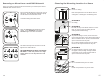
Creating Your multiLINX Network Adding an Alarm to Your multiLINX Network The EX20 SMK Alarm communicates on its own private multiLINX network. This network is created simply by powering up new alarms one at a time. To add an alarm(s) to an existing multiLINX network, perform the following steps. Activate your first alarm by moving the slide switch located on the back side of the alarm in the direction indicated by the arrow. The slide switch will lock into place when fully positioned.
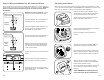
Removing an Alarm from a multiLINX Network Choosing the Mounting Location in a Room In the event that an alarm must be removed from your network, the alarm’s multiLINX data must be erased. BEST Center on ceiling. Press and hold the button on the front cover of the alarm. The red FIRE light will flash rapidly and the alarm will sound three tones. Note: Avoid placement of the alarms close to ceiling fans or heating/air conditioning vents. Continue holding the button down.
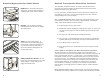
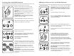
How to Mount the Battery Powered Alarm How to Mount the Battery Powered Alarm 1 Mark Situation B: No Wood If no wood is present, use a Phillips screwdriver to screw the two plastic wall anchors into the pre-drilled holes until fully seated. Then secure the mounting bracket to the wall anchors using the two 1” screws. Place the mounting bracket against the ceiling or wall, and using the mounting bracket as a template, mark the top and bottom holes with a pencil.
How to Wire and Mount the AC Powered Alarm Cleaning Your Alarm When installing an AC powered alarm (Model EX20AC SMK), the mounting location is determined by the position of the electrical box that will power the alarm. Electrical power to the box must be disconnected prior to alarm connection and installation! Over time dust might collect inside your alarm, altering its performance. If this occurs, the unit can false alarm or the WARNING icon will flash and the horn will chirp every 30 seconds.
Alarm Specifications Important Fire/Emergency Safety Information Operating Voltage EX20 SMK EX20-AC SMK Standby Current EX20 SMK EX20-AC SMK Alarm Current EX20 SMK EX20-AC SMK Battery Type Sensitivity Operating Ambient Temperature Operating Humidity Alarm Dimensions Mounting Base Dimensions Weight Heat Sensing Fixed Temperature Rate of Rise 120mA (max.) 25mA (max.) Non-replaceable Lithium Manganese 2.1±1.1% Obscuration 40°F - 100°F 0 - 95% Non-condensing 5.1” x 5.1” x 2.125” 5.0” x 5.0” 0.
Warning! Limitations of Smoke Alarms Limited Warranty Wireless smoke alarms have been proven to be both effective and reliable, but they may not be effective under all conditions. No alarm design can offer total protection of life and property. A smoke alarm is not a substitute for an adequate homeowner’s fire insurance or life insurance policy.
25 Year Product Replacement Guarantee After the above Limited Warranty has expired, commencing on the first day of the 25th month and extending through the last day of the 324th month following the date of purchase, the manufacturer of the Exigent Smoke Alarm guarantees to repair or replace the smoke alarm at a preferred owner discounted price which includes shipping and handling and is adjusted annually.