LAZER Z ADVANTAGE SERIES MODELS ® For Serial Nos. 790,000 & Higher Part No. 4500-466 Rev.
WARNING CALIFORNIA Proposition 65 Warning The engine exhaust from this product contains chemicals known to the State of California to cause cancer, birth defects, or other reproductive harm. Important: When the mower is used or operated on any California forest, brush or grass covered land, a working spark arrester must be attached to the muffler. If not, the operator is violating state law, Section 4442 Public Resource Code. To acquire a spark arrester for your unit, see your Engine Service Dealer.
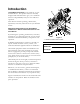
Introduction CONGRATULATIONS on the purchase of your Exmark Mower. This product has been carefully designed and manufactured to give you a maximum amount of dependability and years of trouble-free operation. This manual contains operating, maintenance, adjustment, and safety instructions for your Exmark mower. BEFORE OPERATING YOUR MOWER, CAREFULLY READ THIS MANUAL IN ITS ENTIRETY.
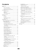
Contents Deck Removal ............................................... 41 Pump Drive Belt Tension............................... 41 Deck Belt Tension ........................................ 41 Adjusting the Parking Brake........................... 41 Electric Clutch Adjustment............................ 42 Motion Control Linkage Adjustment ............. 42 Motion Control Damper Adjustment............. 43 Motion Control Neutral Lock Pivot Adjustment ...............................................
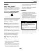
Safety Safety • Never let children or untrained people operate or service the equipment. Local regulations may restrict the age of the operator. Safety Alert Symbol • The owner/user can prevent and is responsible for accidents or injuries occurring to himself or herself, other people or property.
Safety DANGER DANGER In certain conditions gasoline is extremely flammable and vapors are explosive. A fire or explosion from gasoline can burn you, others, and cause property damage. In certain conditions during fueling, static electricity can be released causing a spark which can ignite gasoline vapors. A fire or explosion from gasoline can burn you and others and cause property damage. • Fill the fuel tank outdoors in an open area, when the engine is cold. Wipe up any gasoline that spills.
Safety • Never operate the mower with damaged guards, shields, or covers. Always have safety shields, guards, switches and other devices in place and in proper working condition. • Never mow with the discharge deflector raised, removed or altered unless there is a grass collection system or mulch kit in place and working properly. • Do Not change the engine governor setting or overspeed the engine.
Safety • Be aware of the mower discharge path and direct discharge away from others. • Do Not operate the mower under the influence of alcohol or drugs. • Use extreme care when loading or unloading the machine into a trailer or truck. • Use care when approaching blind corners, shrubs, trees, or other objects that may obscure vision. Slope Operation Use Extreme caution when mowing and/or turning on slopes as loss of traction and/or tip-over could occur.
Safety • Disconnect battery or remove spark plug wire before making any repairs. Disconnect the negative terminal first and the positive last. Reconnect positive first and negative last. WARNING There is no rollover protection when the roll bar is down. Wheels dropping over edges, ditches, steep banks, or water can cause rollovers, which may result in serious injury, death or drowning. • Use care when checking blades. Wrap the blade(s) or wear gloves, and use caution when servicing them.
Safety Safety and Instructional Decals • Keep all safety signs legible. Remove all grease, dirt and debris from safety signs and instructional labels. • Replace all worn, damaged, or missing safety signs. • When replacement components are installed, be sure that current safety signs are affixed to the replaced components. • If an attachment or accessory has been installed, make sure current safety signs are visible.
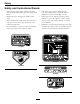
Safety 109-3148 109-7232 1. Fast 2. Slow 3. Neutral 4.
Safety 116-0090 109-8483 1. Throttle–fast 2. Throttle–slow 3. Choke–on 4. Choke–off 116-0157 1.
Safety 116-0906 For Kawasaki Liquid-Cooled Only 116-0211 Message Display 1. 2. 3. 4. 5. Fuel Empty Half Full Battery 6. 7. 8. 9. 10. Hour meter PTO Parking brake Neutral Operator presence switch 116-0752 1. Latch 2. Unlatch PTO Switch Symbols 1. PTO–disengage 109-7069 13 2.
Specifications Specifications Model Numbers Serial Nos: 790,000 and Higher LZAS20BV484; LZAS20KC484; LZAS23KC524; LZAS25KC604; LZAS26LKA604; LZAS27KC524; LZAS27KC604; LZAS29KA724 Systems – Kawasaki Liquid-Cooled: 20 amps • Battery Type: BCI Group U1 Engine • Recommended Minimum Battery CCA: 260 CCA • Engine Specifications: See your Engine Owner’s Manual • RPM: – All units except LZAS20BV484 and LZAS20KC484: Full Speed: 3750 ±50 RPM (PTO not engaged) Idle: 1500 ±100 RPM – LZAS20BV484 and LZAS20KC484: F
Specifications Operator Controls • Armrests: – Standard seat: foam padded adjustable flip-up armrests. – Suspension seat: molded adjustable flip-up armrests. • Seat Safety Switch: • Steering and Motion Control: • • • • • • Note: Motion control levers are adjustable to two heights. – Separate levers, on each side of the console, control speed and direction of travel of the respective drive wheels. – Steering is controlled by varying the position of the levers relative to each other.
Specifications Dimensions • Blade Size: (3 ea.) – 48 inch Deck: 16.25 inches (41.3 cm) Overall Width: – 52 inch Deck: 18.00 inches (45.7 cm) 48 inch Deck 52 inch Deck Without Deck 45.7 inches (116.1 cm) 45.7 inches (116.1 cm) • Blade Spindles: Solid steel spindles with 1.00 inch (25 mm) I.D. bearings. Deflector Up 51.8 inches (131.6 cm) 56.3 inches (143.0 cm) • Deck Drive: Deflector Down 59.6 inches (151.4 cm) 64.8 inches (164.6 cm) 60 inch Deck 72 inch Deck – 60 inch Deck: 20.
Specifications Accessory Weight Table Worksheet: Tread Width: (Center to Center of Tires, Widthwise) Use the table below to determine if extra weight is required for the unit. Identify the accessories and correct deck size and place the corresponding values in the Accessory Score column. If the Total Accessory Score meets the following, add the recommended weight kit. 48 inch Deck 52 inch Deck Drive Wheels 36.2 inches (91.9 cm) 36.2 inches (91.9 cm) Caster Wheels 32.8 inches (83.3 cm) 32.
Product Overview Product Overview *60 inch units which already have an under toe board mount weight as standard requires 116-1238 front toe board top mount kit instead of 116-1173.
Operation Choke Control Operation Located on right console (black lever) (see Figure 6). Note: Determine the left and right sides of the machine from the normal operating position. The choke is used to aid in starting a cold engine. Moving the choke lever forward will put the choke in the “ON” position and moving the choke lever to the rear, to the detent, will put the choke in the “OFF” position. Do Not run a warm engine with choke in the “ON” position.
Operation Note: The LCD indicator appears in the message display on the RH console when the park brake is engaged (see Figure 9). disengaged to start engine. (It is not necessary for the operator to be in the seat to start the engine.) Pull the lever up and rearward to engage the brake. Hour Meter Depress the release button and push downward to disengage the brake. Located on the right console in the message display (see Figure 6 and Figure 9).
Operation Fuel Shut-Off Valve Located behind and below the seat. The fuel shut-off valve is used to shut off the fuel when the machine will not be used for a few days, during transport to and from the jobsite, and when parked inside a building. Align valve handle with the fuel line to open. Rotate 90° to close. Fuel Gauge Figure 10 1. Handle in “released” position 2. Handle in “operating” position Located on the right console in the message display (see Figure 6 and Figure 9).
Operation Coolant Temperature Gauge (Kawasaki Liquid-Cooled Only) In the non-latching position, the deck will automatically return to the cutting height when the pedal is lowered (see item 3 in Figure 12). Located on the right console (see Figure 6). The coolant temperature gauge monitors the temperature of the engine coolant. During normal operating conditions the gauge should be in the green range.
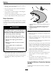
Operation 2. Apply forward pressure to the upper hoop of the roll bar. 3. Pull the knob and rotate 90° to hold in the unlatched position to lower the roll bar. 4. To return to the operate position, raise the roll bar, and then rotate knobs 90° so that the tabs interlock partially. Apply forward pressure to the roll bar upper hoop and observe that the knobs return to the completely latched position. Figure 14 1. Engaged 2. Partially engaged — Do Not operate with ROPS in this condition.
Operation Stopping the Engine attempts. Failure to follow these guidelines can burn out the starter motor. 1. Bring the unit to a full stop. 7. If the choke is in the “ON” position, gradually return choke to the “OFF” position as the engine warms up. 2. Disengage the PTO. 3. Move the motion control levers out to the neutral lock position. Engaging the PTO 4. Engage the parking brake. 5. Place the throttle midway between the “SLOW” and “FAST” positions.
Operation Figure 16 1. Front of Unit 2. Forward 3. Neutral 4. Reverse Driving in Reverse 1. Move the motion control levers inward to the neutral operate position. 2. To move rearward in a straight line, move both levers rearward with equal pressure. Figure 15 1. Neutral lock position (handles out) 2. Neutral operate position (handles in) 3. Front of Unit 4. Forward To turn left or right, release pressure on the motion control lever toward the desired turn direction. 5. Neutral (operate) 6.
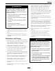
Operation Figure 18 For cutting heights above 3.5 inches (90 mm) use the bottom hole. The rollers will still be effective against scalping. 1. Anti-scalp roller mounting bracket 2. Cutting height Figure 17 1. Deck foot pedal 2. Height adjustment pin 3. Cut of height decal 4. Transport lock control For Maximum Deck Flotation, place the rollers one hole position lower. Rollers should maintain 1/4 inch (6.4 mm) clearance to the ground. Do Not adjust the rollers to support the deck. 5.
Operation Transporting WARNING Loading a unit on a trailer or truck increases the possibility of backward tip-over. Backward tip-over could cause serious injury or death. Transporting a Unit Use a heavy-duty trailer or truck to transport the machine. Lock brake and block wheels. Securely fasten the machine to the trailer or truck with straps, chains, cable, or ropes. Be sure that the trailer or truck has all necessary lighting and marking as required by law. Secure a trailer with a safety chain.
Operation Important: Do Not attempt to turn the unit while on the ramp, you may lose control and drive off the side. Avoid sudden acceleration when driving up a ramp and sudden deceleration when backing down a ramp. Both maneuvers can cause the unit to tip backward.
Maintenance Maintenance Note: Determine the left and right sides of the machine from the normal operating position. WARNING WARNING While maintenance or adjustments are being made, someone could start the engine. Accidental starting of the engine could seriously injure you or other bystanders. The engine can become very hot. Touching a hot engine can cause severe burns. Allow the engine to cool completely before service or making repairs around the engine area.
Maintenance Maintenance Service Interval Every 500 hours Every 4,000 hours Yearly Maintenance Procedure • • • • Change the hydraulic filter and fluid. Check the wheel hub slotted nut torque specifications. Check the wheel lug nuts. Check the park brake adjustment. • Change engine coolant. Dex-Cool© extended life coolant (orange color) • Grease the deck and pump idler pivots. • Grease the front caster pivots.
Maintenance Voltage Reading Percent Charge Maximum Charger Settings 11.7–12.0 0–25% 14.4 volts/4 3 Hours amps 11.7 or less 0% 14.4 volts/2 6 Hours or More amps Charging Interval Check Mower Blades Service Interval: Before each use or daily 1. Stop engine, wait for all moving parts to stop, and remove key. Engage parking brake. Figure 21 1. Use wrench here for blade installation. This nut has been torqued to 140–145 ft-lb (190–197 N-m) 2.
Maintenance Check Rollover Protections Systems (Roll Bar) Knobs lock position. The operator does not need to be in the seat to start the engine. Try to start with operator in seat, parking brake disengaged, PTO disengaged and motion control levers in the neutral lock position - starter must not crank. Service Interval: Before each use or daily Check that both the mounting hardware and the knobs are in good working condition. Make sure the knobs are fully engaged with the ROPS in the raised position.
Maintenance Manual for additional information.) 6. Use oil recommended in engine owner’s manual. Do Not overfill. Start the engine and check for leaks. 1. Stop engine, wait for all moving parts to stop, and remove key. Engage parking brake. 7. Wipe up any spilled oil from engine deck mounting surfaces. 2. Loosen retaining clips and remove air cleaner compartment cover. Check Hydraulic Oil Level 3. Remove paper element. Check the condition of the paper element. Replace if dirty, bent or damaged.
Maintenance Check Tire Pressures * See step 3 for special lubrication instructions on the front caster pivots. Service Interval: Every 50 hours 1. Stop engine, wait for all moving parts to stop, and remove key. Engage parking brake. 2. Check tire pressure in drive tires. 3. Inflate drive tires to 13 psi (90 kPa). 4. Semi-pneumatic caster tires Do Not need to be inflated. Note: Do Not add any type of tire liner or foam fill material to the tires.
Maintenance Lubricate Deck Lift Pivot 6. Pack the bearings with a NGLI grade #1 multi-purpose grease. Service Interval: Every 100 hours 7. Insert one bearing, one new seal into the wheel. 1. Stop engine, wait for all moving parts to stop, and remove key. Engage parking brake. Note: Seals (Exmark P/N 103-0063) must be replaced. 2. Lubricate deck lift pivot with a spray type lubricant or light oil. 8.
Maintenance unless it is felt the oil has been contaminated or been extremely hot. Changing oil unnecessarily could damage hydraulic system by introducing contaminants into the system. CAUTION Raising the mower deck for service or maintenance relying solely on mechanical or hydraulic jacks could be dangerous. The mechanical or hydraulic jacks may not be enough support or may malfunction allowing the unit to fall, which could cause injury.
Maintenance Check Engine Coolant Level (Kawasaki Liquid-Cooled Only) Change Engine Coolant (Kawasaki Liquid-Cooled Only) Service Interval: Before each use or daily Service Interval: Every 4,000 hours/Every 4 years (whichever comes © extended first) Dex-Cool© life coolant (orange color) 1. Stop engine and wait for all moving parts to stop. Make sure unit is on a level surface. 2. Check with engine cold. 1. Stop engine, wait for all moving parts to stop, and remove key. Engage parking brake.
Maintenance 2. Wait for muffler to cool. WARNING 3. If any breaks in the screen or welds are observed, replace arrester. Engine compartment contains open belt drives, fans, and other rotating components that can cause injury. Fingers, hands, loose clothing, or jewelry can get caught by the rotating fan and drive shaft. 4. If plugging of the screen is observed, remove arrester and shake loose particles out of the arrester and clean screen with a wire brush (soak in solvent if necessary).
Maintenance Adjustments Note: Disengage PTO, shut off engine, wait for all moving parts to stop, engage parking brake, and remove key before servicing, cleaning, or making any adjustments to the unit. CAUTION Raising the mower deck for service or maintenance relying solely on mechanical or hydraulic jacks could be dangerous. The mechanical or hydraulic jacks may not be enough support or may malfunction allowing the unit to fall, which could cause injury.
Maintenance 12. Re-measure until all four sides are the correct height. Tighten all the nuts on the deck lift arm assemblies. 13. Lower discharge deflector. 14. If the four deck links do not have enough adjustment to achieve accurate cut height with the desired rake, the single point adjustment can be utilized to gain more adjustment (see Figure 30). Figure 28 1. 3 1/4 inches (8.3 cm) 2. Back blade tip 3. Front blade tip 4. 3 inches (7.6 cm) 5. Level surface 10.
Maintenance Deck Removal 7. Disconnect the deck strut and panhard from the deck. Before servicing or removing the deck, the spring loaded deck arms must be locked out. 8. Raise the front of the machine and slide the deck left or right to remove. 9. Lower the front of the machine. WARNING Deck lift arm assemblies have stored energy. Removing the deck with out releasing the stored energy can cause serious injury or death.
Maintenance 16. Install the rear tires and torque lug nuts to 90-95 ft-lb (122-129 N-m). 17. Remove jack stands. Electric Clutch Adjustment No adjustment necessary. Motion Control Linkage Adjustment Located on either side of the fuel tank, below the seat are the pump control linkages. Rotating the pump linkage with a 1/2 inch wrench allows fine tuning adjustments so that the machine does not move in neutral. Any adjustments should be made for neutral positioning only. Figure 32 Left Hand Brake Shown 1.
Maintenance Note: The motion control lever needs to be in neutral while making any necessary adjustments. 7. Bring the motion control levers into the neutral position. Adjust pump control rod lengths by rotating the double nuts on the rod in the appropriate direction until the wheels slightly creep in reverse (Figure 33). Move the motion control levers to the reverse position and while applying slight pressure to the lever allow the reverse indicator springs to bring the levers back to neutral.
Maintenance Motion Control Handle Adjustment 1. Loosen the screws on a cover plate (see Figure 37). Adjusting the height: 2. Slide the cover plate backward or forward to adjust the travel of the lever and tighten the screws. The motion control levers can be adjusted higher or lower for maximum operator comfort. 3. Drive the machine and check the full forward tracking. 1. Remove the two bolts holding the control lever to the control arm shaft (Figure 36). 4.
Maintenance Cleaning Clean Engine and Exhaust System Area Service Interval: Before each use or daily (May be required more often in dry or dirty conditions.) CAUTION Excessive debris around engine cooling air intake and exhaust system area can cause engine, exhaust area, and hydraulic system to overheat which can create a fire hazard. Figure 38 1. Spring disc washers Clean all debris from engine and exhaust system area. 1. Stop engine, wait for all moving parts to stop, and remove key.
Maintenance Waste Disposal Removing debris from the hydro fan cooling guards will allow the hydro system to run cooler and improve the life of the hydro system. Motor Oil Disposal 1. Stop engine, wait for all moving parts to stop, and remove key. Engage parking brake. 2. Slide seat all the way back, then lift the seat to access the LH and RH hydro drive area. Engine oil and hydraulic oil are both pollutants to the environment.
Troubleshooting Troubleshooting Important: It is essential that all operator safety mechanisms be connected and in proper operating condition prior to mower use. When a problem occurs, do not overlook the simple causes. For example: starting problems could be caused by an empty fuel tank. The following table lists some of the common causes of trouble. Do not attempt to service or replace major items or any items that call for special timing of adjustment procedures (such as valves, governor, etc.).
Troubleshooting Problem Engine loses power Engine overheats. (Coolant temperature gauge is approaching the red zone or warning buzzer emits beep.) Possible Cause Corrective Action 1. Engine load is excessive 1. Reduce the ground speed. 2. Air cleaner is dirty. 3. Oil level in the crankcase is low. 4. Cooling fins and air passages for the engine are plugged. 5. Dirt in fuel filter. 6. Dirt, water, or stale fuel is in the fuel system. 2. Clean or replace the air cleaner element. 3.
RECTIFIER START TERMINAL R TERMINAL S 49 NONE B+R+I+A B+R+I+S 2. RUN 3. START CIRCUIT "MAKE" TERMINAL S TERMINAL B TERMINAL R TERMINAL A 1. OFF POSITION IGNITION TERMINAL I TERMINAL I BATTERY TERMINAL B CONNECTIONS ACCESSORY TERMINAL TERMINAL A A B 2 1 2 1 2 1 2 1 1 2 1 2 B A PINK LT.
NONE B+R+I+A B+R+I+S 2. RUN 3. START CIRCUIT "MAKE" TERMINAL S TERMINAL B TERMINAL R TERMINAL A 1.
A BK BK - GND S B BU SW2 (PTO SWITCH) C FUEL SENDER PK + 2 BK BN BN 3 5 BN 8 F3 B PK 1 BN V 4 A PTO CLUTCH 4 10A BK BN 7 U2 TVS DIODE 5 SW5 BK 8 3 (NEUT_L) SW4 (NEUT_R) PTO PK ACCESSORIES FUEL GROUND PK 6 2 Y LTGR PK BRAKE 4 W 7 9 (BRAKE) SW6 GND 15A F4 HOUR METER 11 BK 8 10 T PK 7 1 12 OR B+ KEY_S GN (SEAT) SW7 BN PK OR GY R R OR PK 5 I SW1 (IGNITION) 2 B GN GY GY 1 S V 3 R PK 4 OPTIONAL NEUTRAL FUEL_SOLENOID SEAT
GN (+) (s) (P) S 3 BK 2 - 1 O 4 TEMP GAUGE PK OR PK OR ALARM 2 TONE + - BK BK A GND S B BU SW2 C FUEL SENDER PK + 2 PK 3 BN BN BK BN B BN V A PTO CLUTCH 4 PK 1 4 BK BN 7 U2 SW4 8 3 (NEUT_L) TVS DIODE BK 5 SW5 PTO (PTO SWITCH) F3 (NEUT_R) FUEL GROUND 5 8 10A 2 Y PK 6 11 F4 SW6 GND 15A W 7 9 (BRAKE) 4 8 HOUR METER LTGR BK SEAT PK NEUTRAL FUEL_SOLENOID BRAKE 10 T PK 12 1 OR SW7 GN (SEAT) BN PK OR GY R OR R 2 B 4 A V 3 R
Schematics Hydraulic Diagram 53
Exmark Lazer Z and Lazer Z AS Turf Equipment 3 Year Limited Commercial Warranty 5 Year or 750 Hours Limited Consumer Warranty General Warranty Conditions and Products Covered Exmark Mfg. Co. Inc. and its affiliate, Exmark Warranty Company, pursuant to an agreement between them, jointly warrant on the terms and conditions herein, that we will repair, replace or adjust any part on these products and found by us (in the exercise of our reasonable discretion) to be defective in factory materials or workmanship.
Notes: 55
Notes: 56
Service Record Date: Description of Work Done: 57 Service Done By:
SEE EXMARK’S COMPLETE LINE OF ACCESSORIES AND OPTIONS MID-MOUNT RIDING ACCESSORIES AND OPTIONS CUSTOM RIDE SEAT SUSPENSION SYSTEM OPERATOR CONTROLLED DISCHARGE FULL SUSPENSION SEAT ROLL OVER PROTECTION SYSTEM (ROPS) DECK LIFT ASSIST KIT SUN SHADE HITCH KIT TRASH CONTAINER LIGHT KIT TURF STRIPER 12V POWER PORT ULTRA VAC COLLECTION SYSTEM MICRO-MULCH SYSTEM ULTRA VAC QUICK DISPOSAL SYSTEM OUT-FRONT RIDING ACCESSORIES AND OPTIONS CUSTOM RIDE SEAT SUSPENSION SYSTEM SNOW BLADE DUAL-TAIL WHEEL SN