VANTAGE ™ For Serial Nos. 850,000 & Higher Part No. 4500-648 Rev.
WARNING CALIFORNIA Proposition 65 Warning The engine exhaust from this product contains chemicals known to the State of California to cause cancer, birth defects, or other reproductive harm. Important: The engine in this product is not equipped with a spark arrester muffler. It is a violation of California Public Resource Code (CPRC) Section 4442 to use or operate this engine on any forest-covered, brush-covered, or grass-covered land as defined in CPRC 4126.
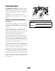
Introduction CONGRATULATIONS on the purchase of your Exmark Mower. This product has been carefully designed and manufactured to give you a maximum amount of dependability and years of trouble-free operation. This manual contains operating, maintenance, adjustment, and safety instructions for your Exmark mower. Figure 1 1. Model and serial number location BEFORE OPERATING YOUR MOWER, CAREFULLY READ THIS MANUAL IN ITS ENTIRETY. Model No.
Contents Electric Clutch Adjustment............................ 38 Motion Control Neutral Adjustment .............. 39 Motion Control Tracking Adjustment ............ 40 Check the Neutral Switch Alignment ................................................................. 40 Adjust RH Motion Control Handle Position..................................................... 41 Caster Pivot Bearings Pre-Load Adjustment ............................................... 42 Cleaning ......................................
Safety Safety • Never let children or untrained people operate or service the equipment. Local regulations may restrict the age of the operator. Safety Alert Symbol • Only adults and mature teenagers should operate a mower, and even mature teenagers should have adult supervision. Be sure a teenager: This Safety Alert Symbol (Figure 2) is used both in this manual and on the machine to identify important safety messages which must be followed to avoid accidents. 1.
Safety DANGER DANGER In certain conditions gasoline is extremely flammable and vapors are explosive. A fire or explosion from gasoline can burn you, others, and cause property damage. In certain conditions during fueling, static electricity can be released causing a spark which can ignite gasoline vapors. A fire or explosion from gasoline can burn you and others and cause property damage. • Fill the fuel tank outdoors on level ground, in an open area, when the engine is cold.
Safety Operation – After striking a foreign object or abnormal vibration occurs (inspect the mower for damage and make repairs before restarting and operating the mower). – Before clearing blockages. – Whenever you leave the mower. • Stop engine, wait for all moving parts to stop, and engage parking brake: – Before refueling. – Before dumping the grass catcher. – Before making height adjustments. WARNING Operating engine parts, especially the muffler, become extremely hot.
Safety Maintenance and Storage occur. The operator is responsible for safe operation on slopes. • Disengage drives, lower implement, set parking brake, stop engine and remove key or disconnect spark plug wire. Wait for all movement to stop before adjusting, cleaning or repairing. DANGER Operating on wet grass or steep slopes can cause sliding and loss of control.
Safety DANGER WARNING Charging or jump starting the battery may produce explosive gases. Battery gases can explode causing serious injury. Removing standard original equipment parts, or using non-Exmark replacement parts and accessories may alter the warranty, traction, and safety of the machine. Failure to use original Exmark parts could cause serious injury or death. • Keep sparks, flames, or cigarettes away from battery. • Ventilate when charging or using battery in an enclosed space.
Safety Safety and Instructional Decals • Keep all safety signs legible. Remove all grease, dirt and debris from safety signs and instructional labels. • Replace all worn, damaged, or missing safety signs. • When replacement components are installed, be sure that current safety signs are affixed to the replaced components. • If an attachment or accessory has been installed, make sure current safety signs are visible.
Safety 116-0404 116-3260 1. Forward position - faster 2.
Safety 116-3290 116-1886 116-1887 1. Fast 2. Slow 3. Neutral 4. Reverse 116-3067 1. PTO-on 2. PTO-off 3. Fast 4. Slow 5. Choke-on 6.
Specifications Specifications Model Numbers Serial Nos: 850,000 and Higher VT20KAS484; VT20KAS524; VT24KAS484; VT24KAS524; VT24KAS484CA; VT24KAS524CA Systems necessary for the operator to be on the platform to start the engine.) Engine • Mower blades will stop if the right side motion control lever is moved or released into the PTO disengage position.
Specifications Dimensions Tires & Wheels Drive Front Caster Pneumatic (Air-Filled) SemiPneumatic Quantity 2 2 Tread Turf Master Smooth Size 20 x 10.00–8 11 x 4.00-5 Ply Rating 4 Pressure 14 psi (97 kPa) Overall Width: 48 inch Deck 52 inch Deck Deflector Up 51.8 inches (131.6 cm) 56.3 inches (143.0 cm) Deflector Down 59.6 inches (151.4 cm) 64.8 inches (164.6 cm) Overall Length: Cutting Deck • Cutting Width: – 48 inch Deck: 48 inches (121.
Product Overview Torque Requirements Bolt Location Torque Cutter Housing Spindle Nut 140-145 ft-lb (190-197 N-m) Blade Mounting Bolt (lubricate with anti-seize) 55-60 ft-lb (75-81 N-m) Engine Deck/Mower Deck Support Mount Bolts 30-35 ft-lb (41-47 N-m) Engine Mounting Bolts 15-20 ft-lb (20-27 N-m) Wheel Lug Nuts 90-95 ft-lb (122-129 N-m) Wheel Hub Nuts 175-225 ft-lb (237-305 N-m) Wheel Motor Mounting Bolts 30-35 ft-lb (41-47 N-m) Product Overview Figure 3 1. Platform 2. Fuel Cap 3.
Operation Operation rear, to the detent, will put the choke in the “OFF” position. Do Not run a warm engine with choke in the “ON” position. Note: Determine the left and right sides of the machine from the normal operating position. Controls Motion Control Levers The motion control levers, located on each side of the top console, control the forward and reverse motion of the machine. Moving the levers forward or backward turns the wheel on the same side forward or reverse respectively.
Operation Hour Meter The brake lever engages a parking brake on the drive wheels. Located on the LH side of the front control console in the message display (see Figure 5 and Figure 7). Note: The LCD indicator appears in the message display on the front console when the park brake is engaged (see Figure 5 and Figure 7). The hour meter records the number of hours that the engine has run. To engage the brake, pull the lever rearward and to the right to position into the engaged position.
Operation Pre-Start The fuel gauge monitors the amount of fuel in the tank. Fill fuel tank on level ground. For best results use only clean, fresh regular grade unleaded gasoline with an octane rating of 87 or higher. Drive Wheel Release Valves Located on the left rear corner of the hydrostatic pumps. Important: Never use methanol, gasoline containing methanol, gasohol containing more than 10% ethanol, premium gasoline, or white gas because the fuel system could be damaged.
Operation Disengaging the PTO Important: Do Not crank the engine continuously for more than ten seconds at a time. If the engine does not start, allow a 60 second cool-down period between starting attempts. Failure to follow these guidelines can burn out the starter motor. 1. Set the throttle midway between the “SLOW” and “FAST” positions. 2. Push down on the PTO switch to disengage the blades.
Operation Important: To begin movement (forward or backward), the brake lever must be disengaged (pushed forward) before the motion control levers can be moved or the engine will stop. When the RH motion control lever is positioned fully outward (apart), the drive system is in the PTO disengage position (Figure 8). Note: The “N” LCD indicator appears when the RH lever is in the PTO disengage position.
Operation Figure 11 Figure 10 1. Front of the machine 2. Control tower To turn left or right, release pressure on the motion control lever toward the desired turn direction. 3. Unlock 3. To stop, position both motion control levers in the neutral operate position. 4. Forward position — faster 5. Backward position — slower 6. Lock 4. Move the bar forward to obtain the fastest speed. Move the bar backward to obtain the slowest speed. 5.
Operation WARNING The operator platform is heavy and may cause injury when lowering and raising the operator platform. The platform may suddenly drop if not supported when the latch pin is pulled out. • Do Not put your hands or fingers in the platform pivot area when lowering or raising the operator platform. • Make sure the platform is supported when the latch pin is pulled out. Figure 12 1. Platform 2. Raise upward 3.
Operation Adjusting the Cutting Height The cutting height of the mower deck is adjusted from 1 to 5 inches (2.5 cm to 12.7 cm) in 1/4 inch (6.4 mm) increments. 1. Stop the machine and move the motion control levers to the neutral position. 2. Disengage the PTO. 3. Raise and lock the deck to the 5 inch (12.7 cm) transport position. The deck is raised by pulling the deck lift handle rearward and to the right to place it into the transport lock position. Figure 15 1. Height adjustment pin 2.
Operation Avoid sudden acceleration when driving up a ramp and sudden deceleration when backing down a ramp. Both maneuvers can cause the unit to tip backward. WARNING Loading a unit on a trailer or truck increases the possibility of backward tip-over. Backward tip-over could cause serious injury or death. • Use extreme caution when operating a unit on a ramp. • Use only a single, full width ramp; Do Not use individual ramps for each side of the unit.
Maintenance Maintenance Note: Determine the left and right sides of the machine from the normal operating position. WARNING WARNING While maintenance or adjustments are being made, someone could start the engine. Accidental starting of the engine could seriously injure you or other bystanders. The engine can become very hot. Touching a hot engine can cause severe burns. Allow the engine to cool completely before service or making repairs around the engine area.
Maintenance Maintenance Service Interval Every 500 hours Maintenance Procedure • Replace the secondary air cleaner element (May need more often under severe conditions. See the Engine Owner’s Manual for additional information.) • Change the hydraulic filter and fluid (Every 250 hours/yearly if using Mobil 1 15W50) • Check the wheel hub torque specification. • Check the wheel lug nuts. • Check the battery charge. Monthly • Grease the front caster pivots. • Grease the deck belt idler pivot.
Maintenance Voltage Reading Percent Charge Maximum Charger Settings 11.7–12.0 0–25% 14.4 volts/4 3 Hours amps 11.7 or less 0% 14.4 volts/2 6 Hours or More amps Charging Interval CAUTION Connecting the jumper cables incorrectly (wrong polarity) can immediately damage the electrical system. Be certain of battery terminal polarity and jumper cable polarity when hooking up batteries. Recommended Jump Starting Procedure Note: The following instructions are adapted from the SAE J1494 Rev. Dec.
Maintenance 6. Raise the cushion and slide it onto the pins on both sides of the machine (Figure 17). 7. Push the plastic slides into the cushion bracket and secure them with a hairpin. Figure 16 1. 2. 3. 4. 5. 6. 7. Positive (+) cable on discharged battery Positive (+) cable on booster battery Negative (–) cable on the booster battery Negative (–) cable on the engine block Booster battery Discharged battery Engine block 4.
Maintenance A. Install bushing through blade with bushing flange on bottom (grass) side of blade. WARNING Incorrect installation of the blade or components used to retain the blade can be dangerous. Failure to use all original components and assembled as shown could allow a blade or blade component to be thrown out from under the deck resulting in serious personal injury or death. Always install the original Exmark blades, blade bushings, and blade bolts as shown. Figure 18 1.
Maintenance Manual for additional information.) Every 500 hours—Replace the secondary air cleaner element (May need more often under severe conditions. See the Engine Owner’s Manual for additional information.) 1. Stop engine, wait for all moving parts to stop, and remove key. Engage parking brake. 2. See the Engine Owner’s Manual for maintenance instructions. 3. Move the motion control levers forward. The engine should initiate shutdown after momentary pause. 4.
Maintenance 2. Lubricate fittings with NGLI grade #2 multi-purpose gun grease. 1. Stop engine and wait for all moving parts to stop. Engage parking brake. Refer to the following chart for fitting locations and lubrication schedule. 2. Clean area around hydraulic reservoir cap and remove cap. Oil level should be to the top of the baffle inside the tank. If not, add oil. Use Exmark Premium Hydro oil. Replace hydraulic reservoir cap and tighten until snug. Do Not overtighten.
Maintenance 13. Torque the nut to 75-80 in-lb (8-9 N-m), loosen, then re-torque to 20-25 in-lb (2-3 N-m). Make sure axle does not extend beyond either nut. 14. Reinstall the seal guards over the wheel hub and insert wheel into caster fork. Reinstall caster bolt and tighten nut fully. Important: To prevent seal and bearing damage, check the bearing adjustment often. Spin the caster tire. The tire should not spin freely (more than 1 or 2 revolutions) or have any side play.
Maintenance Note: Do Not change hydraulic system oil (except for what can be drained when changing filter), unless it is felt the oil has been contaminated or been extremely hot. Changing oil unnecessarily could damage hydraulic system by introducing contaminates into the system. 2. Carefully clean area around filter. It is important that no dirt or contamination enter hydraulic system. 3. Unscrew filter to remove and allow oil to drain from reservoir.
Maintenance Note: It is necessary to lightly touch the charge pump cap with your hand to check the pump temperature. If the cap is too hot to touch, turn off engine. The pumps may be damaged if the pump becomes too hot. WARNING Hot exhaust system components may ignite gasoline vapors even after the engine is stopped. Hot particles exhausted during engine operation may ignite flammable materials. Fire may result in personal injury or property damage.
Maintenance Adjustments • On clutch arm assembly between bearings and shaft and between lower sheave and shaft. Note: Disengage PTO, shut off engine, wait for all moving parts to stop, engage parking brake, and remove key before servicing, cleaning, or making any adjustments to the unit. • Between pump shafts and sheaves. Dielectric Grease Dielectric grease is used on all blade type electrical connections to prevent corrosion and loss of contact.
Maintenance 4. Check and adjust the side to side blade level if you have not checked the setting; refer to Deck Leveling. 5. Carefully rotate the blades front to rear (Figure 24). Measure from the tip of the front blade to the level surface and the tip of the rear blade to the level surface on all blades. The blades should be 1/4 inch (6.4 mm) lower in the front than in the rear. Figure 22 1. Blades front to rear 2. Measure here 7.
Maintenance Figure 27 1. Adjustment screw Figure 26 1. Rear lift points 7. Turn the adjustment screw until the blade tips match 3 inches (7.6 cm). 2. Engine deck brackets 7. To raise the front of the mowing deck, tighten the front locking nuts by the same amount on both front adjusting rods. Tighten both rear locking nuts. Check the side to side level of the mower again; refer to Deck Leveling. Pump Drive Belt Tension Self-tensioning - No adjustment necessary.
Maintenance 4. To adjust the brake, remove the hairpin, washer, and clevis pin from the lower brake lever and yoke as shown in Figure 28. Figure 29 Figure 28 1. Jam nut 2. Yoke 3. Clevis pin 1. Switch 2. 1/8 inch (3mm) gap needed between switch and brake lever 4. Lower brake lever 5. Washer 6. Hairpin 3. Brake lever 5. Loosen the jam nut. 12. If needed, loosen the screws holding the switch and adjust the switch. 6. Rotate the yoke. To tighten the brake, rotate the yoke up.
Maintenance 6. Loosen the lock nuts on the turnbuckle on the RH motion control (as viewed from the rear of the machine — see Figure 32). With the right motion control in the PTO disengage position, hold the LH motion control in the position determined in step 4 or 5. Rotate the turnbuckle until the LCD indicator comes on. Figure 30 1. Adjusting nut 2. Slot 3. Feeler gauge Motion Control Neutral Adjustment Figure 32 Check to see if an adjustment is required: 1. Lock nut 2. Turnbuckle 1.
Maintenance Check the Neutral Switch Alignment 1. Park the machine on a level surface and disengage the blade control switch. 2. Stop engine, wait for all moving parts to stop, and remove the key or spark plug wire(s). 3. Set the height of cut to the 3 inch (7.6 cm) position. 4. Perform the Motion Control Neutral Adjustment and Motion Control Tracking Adjustment as stated in the Maintenance section. Figure 33 1. Rotate to increase speed 2. Turnbuckle 3. Rotate to decrease speed 5.
Maintenance close together as possible without touching (approximately .06 inch (1.5 mm) gap is desirable). The switch mounting plate can be moved up or down to adjust the position of the lower neutral switch. 8. Check the function of the neutral switches by temporarily replacing the key. With the engine off, turn the ignition switch to the “ON” position. Locate the LCD indicator in the message display. Raise and lower the deck. A.
Maintenance Figure 38 Figure 37 1. 2. 3. 4. 1. Spring disc washers Switch Cam Right motion control lever in the neutral operate position 1/8 inch (3mm) 10. If needed, loosen the screws holding the switch and adjust the switch. 11. Tighten the switch screws. Caster Pivot Bearings Pre-Load Adjustment Remove dust cap from caster and tighten nyloc nut until washers are flat and back off 1/4 of a turn to properly set the pre-load on the bearings.
Maintenance Clean Debris From Machine Cleaning Service Interval: Before each use or daily Clean Engine and Exhaust System Area 1. Stop engine, wait for all moving parts to stop, and remove key. Engage parking brake. 2. Clean off any oil, debris, or grass build-up on the machine and cutting deck, especially under deck belt shields, around the fuel tank, around engine and exhaust area. Service Interval: Before each use or daily (May be required more often in dry or dirty conditions.
Maintenance Battery Disposal DANGER Battery electrolyte contains sulfuric acid, which is poisonous and can cause severe burns. Swallowing electrolyte can be fatal or if it touches skin can cause severe burns. • Wear safety glasses to shield eyes, and rubber gloves to protect skin and clothing when handling electrolyte. • Do Not swallow electrolyte. • In the event of an accident, flush with water and call a doctor immediately. Federal law states that batteries should not be placed in the garbage.
Troubleshooting Troubleshooting Important: It is essential that all operator safety mechanisms be connected and in proper operating condition prior to mower use. When a problem occurs, do not overlook the simple causes. For example: starting problems could be caused by an empty fuel tank. The following table lists some of the common causes of trouble. Do Not attempt to service or replace major items or any items that call for special timing of adjustments procedures (such as valves, governor, etc.).
Troubleshooting Problem Engine overheats. Possible Cause Corrective Action 1. Engine load is excessive. 1. Reduce the ground speed. 2. Oil level in the crankcase is low. 3. Cooling fins and air passages for the engine are plugged. 2. Add oil to the crankcase. 3. Remove the obstructions from the cooling fins and air passages. Mower pulls left or right (with levers fully forward). 1. Tire pressure in drive tires not correct. 1. Adjust tire pressure in the drive tires. 2. Tracking needs adjustment.
PTO SWITCH HOUR METER TAN WHITE 8 7 47 GREEN BLACK BROWN 4 3 2 1 PINK PINK 3 2 1 BROWN 4 5 6 7 8 GRAY YELLOW 5 (N/C) VIOLET 9 6 RED ORANGE 10 (N/C) 11 12 VIEWED FROM BACK OF SWITCH OFF = NO CONNNECTION ON = B I A AND X Y START = B I S S B KEY SW A Y X I 1 OPERATOR PRESENT SW 2 1 2 1 2 I 1 BLUE PTO CLUTCH 2 1 A B S 3 4 5 1 2 RED VIOLET RED PINK PINK PINK 3 4 5 6 FUSE BLOCK VIOLET KEY SWITCH X Y 1 2 BROWN PARK BRAKE SWITCH 1 A 8 ENGINE GROUN
Schematics Electrical Schematic 48
Schematics Hydraulic Diagram 49
Exmark Lazer Z, Lazer Z Advantage Series X, and Vantage Turf Equipment 3 Year Limited Commercial Warranty 5 Year or 750 Hours Limited Consumer Warranty General Warranty Conditions and Products Covered Exmark Mfg. Co. Inc.
Notes: 51
Notes: 52
Service Record Date: Description of Work Done: 53 Service Done By:
G011841 Figure 39 This page may be copied for personal use. 1. The maximum slope you can safely operate the machine on is 20 degrees. Use the slope indicator to determine the degree of slope of hills before operating. Do Not operate this machine on a slope greater than 20 degrees. Fold along the appropriate line to match the recommended slope. 2. Align this edge with a vertical surface, a tree, building, fence pole, etc. 3. Example of how to compare slope with folded edge.
SEE EXMARK’S COMPLETE LINE OF ACCESSORIES AND OPTIONS MID-MOUNT RIDING ACCESSORIES AND OPTIONS CUSTOM RIDE SEAT SUSPENSION SYSTEM OPERATOR CONTROLLED DISCHARGE FULL SUSPENSION SEAT ROLL OVER PROTECTION SYSTEM (ROPS) DECK LIFT ASSIST KIT SUN SHADE HITCH KIT TRASH CONTAINER LIGHT KIT TURF STRIPER 12V POWER PORT ULTRA VAC COLLECTION SYSTEM MICRO-MULCH SYSTEM ULTRA VAC QUICK DISPOSAL SYSTEM OUT-FRONT RIDING ACCESSORIES AND OPTIONS CUSTOM RIDE SEAT SUSPENSION SYSTEM SNOW BLADE DUAL-TAIL WHEEL SN