i
WARNING The engine exhaust from this product contains chemicals known to the State of California to cause cancer, birth defects, or other reproductive harm. IMPORTANT When the mower is used or operated on any California forest, brush or grass covered land, a working spark arrester must be attached to the muffler. If not, the operator is violating state law, Section 442 Public Resource Code. To acquire a spark arrester for your unit, see your Engine Service Dealer.
EXMARK PARTS PLUS PROGRAM EFFECTIVE DATE: September 1, 1995 Program If your Exmark dealer does not have the Exmark part in stock, Exmark will get the parts to the dealer the next business day or the part will be FREE* Guaranteed!! How the Program Works 1. If dealer does not have part in stock for a "down" unit at the time of request by customer, the dealer contacts his distributor by 1:00 p.m., local time, and requests Exmark Parts Plus shipment of six (6) line items or less. 2.
CONGRATULATIONS on the purchase of your Exmark Mower. This product has been carefully designed and manufactured to give you a maximum amount of dependability and years of troublefree operation. OPERATOR'S MANUAL This manual contains assembly, operating, maintenance, adjustment and safety instructions for your Exmark mower. BEFORE OPERATING YOUR MOWER, CAREFULLY READ THIS MANUAL IN ITS ENTIRETY.
TABLE OF CONTENTS 1. SAFETY .............................................................................................PAGE 1.1 Safety Alert Symbol...................................................................................... 1 1.2 Training ........................................................................................................ 1 1.3 Preparation................................................................................................ 1-3 1.4 Operation ........................
1. SAFETY 1.1 SAFETY ALERT SYMBOL THIS SAFETY ALERT SYMBOL IS USED BOTH IN THIS MANUAL AND ON THE MACHINE TO IDENTIFY IMPORTANT SAFETY MESSAGES WHICH MUST BE FOLLOWED TO AVOID ACCIDENTS. THIS SYMBOL MEANS: ATTENTION! BECOME ALERT! YOUR SAFETY IS INVOLVED! The safety alert symbol appears above information which alerts you of unsafe actions or situations and will be followed by the word DANGER, WARNING, or CAUTION.
WARNING POTENTIAL HAZARD ♦ Engine exhaust contains carbon monoxide, which is an odorless deadly poison. WHAT CAN HAPPEN ♦ Carbon monoxide can kill you and is also known to the State of California to cause birth defects. HOW TO AVOID THE HAZARD ♦ Do not run engine indoors or in a small confined area where dangerous carbon monoxide fumes can collect. DANGER POTENTIAL HAZARD ♦ In certain conditions gasoline is extremely flammable and highly explosive.
DANGER POTENTIAL HAZARD ♦ In certain conditions gasoline is extremely flammable and highly explosive. WHAT CAN HAPPEN ♦ A static charge can ignite gasoline vapors. A fire or explosion from gasoline can burn you, others, and cause property damage. HOW TO AVOID THE HAZARD ♦ Purchase and store gasoline only in an approved container. ♦ Always place gasoline containers on the ground away from your vehicle before filling.
1.4.5 Stop the blades when crossing surfaces other than grass; and when transporting the mower to and from the area to be mowed. 1.4.6 Never operate the mower with defective guards, shields, or covers. Always have safety shields, guards, switches, and other devices in place and in proper working condition. 1.4.7 Do Not change the engine governor settings or over-speed the engine. Operating an engine at excessive speed may increase the hazard of personal injury. 1.4.
1.5.5 Keep the mower and fuel container in locked storage to prevent children from playing or tampering with them. 1.5.6 Gasoline powered equipment or fuel containers should not be stored in a basement or any enclosed area, where open pilot lights or heat appliances are present. 1.5.7 Maximum mowing results and safety can only be achieved if the mower is properly maintained and operated correctly. 1.5.8. Check all bolts frequently to maintain proper tightness. 1.5.9.
14 HP Kawasaki,Briggs & Stratton, & 15HP Kohler – All Serial Nos. (Serial Nos. 150,000-189,999: 17 HP Kawasaki PART NO. 323688 LOCATION: Console Serial Nos. 190,000 & Higher 15 & 17 HP Kawasaki PART NO. 323699 LOCATION: Console 14 HP Kawasaki & 15HP Kohler PART NO. 323689 LOCATION: RH Side of Console 15 & 17 HP Kawasaki PART NO. 323691 LOCATION: RH Side of Console PART NO. 303508 LOCATION: Front of Mower Deck, Top Surface 17HP Kawasaki & 16HP B&S Serial Nos. 150,000-189,999 PART NO.
PART NO. 403143 LOCATION: RH Side of Rear Surface of Engine Deck PART NO. 303517 LOCATION: LH Side of Rear Surface of Mower Deck PART NO. 553049 LOCATION: Front of Mower Deck Top Surface 16 HP Briggs & Stratton PART NO. 543631 LOCATION: RH Side Console PART NO. 413421 LOCATION: Left Rear on Top of Engine Deck PART NO. 323540 LOCATION: Front of Mower Deck Top Surface PART NO. 323550 LOCATION:Upper Handle PART NO. 513746 LOCATION: On Engine Blower Housing next to Muffler & on Center Belt Cover PART NO.
PART NO. 413206 LOCATION: Top of Cutter Deck, Under Center Belt Shield (36”) PART NO. 413327 LOCATION: Top of Cutter Deck, Under Belt Shield (48” & 52” Decks) 2. SPECIFICATIONS 2.1 MODEL NUMBER: Serial Nos. 150,000 – 189,999: MHP4816BV; MHP5216BV Serial Nos. 150,000 – 219,999: MHP3614KA; MHP4814KA Serial Nos. 150,000 & Higher: MHP3615KC; MHP4815KC Serial Nos. 160,000 & Higher: MHP4817KA; MHP5217KA Serial Nos. 190,000 & Higher: MHP4815KA Serial Nos. 220,000 & Higher: MHP3615KA 2.2 ENGINE 2.2.
2.7 WHEEL DRIVE SYSTEM: Banded double A-Section V-Belts, single top side idlers and replaceable bolton drive sheaves and brake drums. 2.8 TIRES Drive Front Caster Size16 x 6.50-8 ......9 x 3.50-4 Quantity............................. 2.........................................2 Tread................ Turf Saver/Turf Master .................. Smooth Ply Rating.......................... 4.........................................4 Pressure............... 14 psi(97 kPa).................. 22 psi(152 kPa) 2.
2.11 TORQUE REQUIREMENTS BOLT LOCATION TORQUE Blade Mounting Bolt ......................................................... 75-80 ft-lbs. Cutter Housing Spindle Nut .............................................. 75-80 ft-lbs. Anti-Scalp Roller Bolts...................................................... 40-45 ft-lbs. Mower Deck Support/Engine Deck Mount ........................ 30-35 ft-lbs. Engine Mounting Bolts Briggs & Stratton & 15 & 17 HP Kawasaki .......... 15-20 ft-lbs. Kohler & 14 HP Kawasaki .......
a) Position the throttle control lever (on console) in the full throttle (but not choke) position. You will feel a detent when the throttle lever is approximately 3/4” from the upper end of the slot (this is full throttle position). b) Loosen clamp on engine control plate (See Figures 2, 3 & 4). Attach inner wire of the throttle cable to the control plate lever and position cable clamp, do not tighten clamp.
c) Pull cable upward (pull the cable to the right when facing the control plate on 15 & 17 HP Kawasaki units) until alignment holes in control plate lever and control plate line up. For Kawasaki 15/64” (6mm) drill bit can be inserted through these two holes to align them. For Kohler use a 19/64” drill bit. Once the holes are aligned, tighten clamp onto throttle cable. d) Be sure the choke adjusting screw just contacts the choke lever when the throttle control is in the full throttle position.
FIG 5 BLADE ENGAGEMENT LINKAGE 3.10 Install and adjust shifter lever. a) Remove the 3/8” nyloc nut and spring disc washer from the stud on top of the transmission. Install the shifter lever through slot in shifter lever plate and onto the stud on top of transmission. Be sure the square-hole washer remains between the lever and transmission. Replace the spring disc washer and nyloc nut(see figure 6). Torque the 3/8” nut to 35ft. lbs. (47N.M).
FIG. 8 THIS CLEARANCE SHOULD BE EQUAL 3.11 Install and adjust wheel drive linkages. a) Screw threaded end of drive linkages into swivels in wheel drive idler arms. b) Insert clevis pin from bolt bag through drive linkage, lever and slot in the neutral lock/park brake latches (See Figure 9). Make proper adjustments before adding hairpins. Neutral Lock/Park Brake Latch Clevis Pin Drive Linkage Drive Lever FIG.
Drive Linkage Clevis Pin Drive Lever Left Side Shown Reference for Position Only Neutral Lock/Park Brake Latch Hairpin FIG.
The sharpness of the turn varies by how much the lever is squeezed. If both levers are squeezed all the way back, both brakes will engage and the machine will stop. For straight ahead motion, smoothly release both drive levers to engage both drive wheels simultaneously. 4.1.3 Neutral Lock/Parking Brake Latch: Located directly above the drive levers.
4.1.7 “Off-Run” Switch (B&S and 15 & 17 HP Kawasaki only): Located on the console (Serial No.s 190,000 and higher) or front, left corner of the fuel tank support (Serial No.s 150,000-189,999). Turn key to the “Run” position to allow the engine to be started. Turn key to the “Off” position to shut engine off. 4.1.8 Fuel Shut-Off Valve: Installed in the fuel line midway between the tank and the engine.
DANGER POTENTIAL HAZARD ♦ In certain conditions gasoline is extremely flammable and highly explosive. WHAT CAN HAPPEN ♦ A static charge can ignite gasoline vapors. A fire or explosion from gasoline can burn you, others, and cause property damage. HOW TO AVOID THE HAZARD ♦ Purchase and store gasoline only in an approved container. ♦ Always place gasoline containers on the ground away from your vehicle before filling.
WARNING POTENTIAL HAZARD ♦ Engine exhaust contains carbon monoxide, which is an odorless deadly poison. WHAT CAN HAPPEN ♦ Carbon monoxide can kill you and is also known to the State of California to cause birth defects. HOW TO AVOID THE HAZARD ♦ Do not run engine indoors or in a small confined area where dangerous carbon monoxide fumes can collect. For Kohler and Kawasaki engines: On a cold engine, place the throttle in the full forward “Choke” position.
CAUTION POTENTIAL HAZARD ♦ If the nuetral lock latches are not completely engaged the drive levers could unexpectedly slip into the forward drive position. WHAT CAN HAPPEN ♦ If the drive levers slip into the drive position, the unit could lurch forward and cause injury or property damage. HOW TO AVOID THE HAZARD ♦ Be sure the pins protruding through the slots of each neutral lock latch are completely engaged in the rear slot of each latch.
4.3.9 Changing Gears When changing gears, always squeeze drive levers and/or engage neutral lock latches or park brakes. The shift lever may be moved with a knee or by hand. NOTE: Reverse gear is reverse assist only, the operator must pull the unit backwards. 4.3 TRANSPORTING WARNING POTENTIAL HAZARD ♦ Loading the mower onto a trailer without strong enough or properly supported ramps could be dangerous. WHAT CAN HAPPEN ♦ The ramps could collapse causing the unit to fall, which could cause injury.
WARNING POTENTIAL HAZARD ♦ The engine can become very hot. WHAT CAN HAPPEN ♦ Touching a hot engine can cause severe burns. HOW TO AVOID THE HAZARD ♦ Allow the engine to cool completely before service or making repairs around the engine area. 5.1.1 Check engine oil level. Service Interval: See Engine Owner's Manual a) Make sure engine is stopped and on a level surface. b) Check with engine cool. c) Clean area around dipstick. Remove dipstick and wipe oil off.
a) Disengage blade clutch. b) Stop engine and remove spark plug wire(s). c) Raise deck and block up using proper safety precautions. d) Clean out any grass build-up from underside of deck and in deck discharge chute. e) Inspect blades and sharpen or replace as required. f) If blade removal is necessary, be careful for the sharp cutting edges of the blades. g) Re-install the blades (if they were removed) and torque blade bolts to 7580 ft. lbs.
5.1.6 Check Brake and Wheel Drive Linkage Adjustment Service Interval: Daily Refer to Section 3.11. Note any bent linkage or hardware which may need servicing or replacing. 5.1.7 Service pre-cleaner element and air cleaner. Service Interval: See Engine Owner's Manual 5.1.8 Change engine oil. Service Interval: See Engine Owner's Manual NOTE: Change oil after first five (5) hours of operation. Follow engine manufacturers recommendations for future oil changes. 5.1.9 a) Disengage blade clutch.
5.1.10 Check tire pressures. Service Interval: 40 hrs. a) Stop engine and remove spark plug wire(s). Check air pressure in tires; recommended tire pressure is: rear, 12 to 16 psi; pneumatic casters, 22 psi. b) Inflate tires to pressures stated above. Measure circumference of each drive tire. Adjust tire pressures within the above range to try to make tire circumferences match as closely as possible. NOTE: Front caster tires have permanent tire sealant installed. 5.1.11 Inspect Belt wear.
No. 5 (Clutch Arm Pivot) Located Under Engine Deck No. 7 (Trans. Coupler) Located Below Fuel Tank Support No. 4 & 7 (Idler Arm Pivots) Disassemble and grease once a Month under a “No Load” condition c) Lubricate pivot points with a spray penetrating lubricant as directed below. SPRAY LUBRICANT CHART PIVOT POINT 1. Blade Engagement Lever NO. OF PLACES 1 SERVICE INTERVAL Weekly d) Lubricate drive wheel hubs once a year. First remove wheel, then remove hub cap.
e) Lower Sheave retaining bolt on clutch arm. Adhesives such as “Loctite RC/609 or RC/680”or“Fel-Pro Pro-Lock Retaining I or Retaining II” are used on the following: a) OPC lever hubs and cross-shaft NOTE: Care must be used not to bond the bearing, next to each OPC hub, to the cross shaft which could cause binding of the OPC levers and erratic operation. 5.1.19 An anti-seize compound is used on the following locations: a) Between engine crankshaft and transmission and blade drive sheaves.
clearance to ground. Do Not adjust rollers to support the deck. Be sure roller bolts and nuts are installed with the spring disc washer between head of bolt and mounting bracket. Torque to 40-45 ft-lbs., or loss of roller may result. c) When operating in extremely rough conditions it may be necessary to position the anti-scalp rollers one or two holes higher than described in "b" to prevent damage to the rollers and/or bolt failure(See Figure 14).
b) Be sure mud and grass scraper, on each side, is adjusted properly and centered in the pulley grooves. The pointed part of the scraper should be centered and as deep in the pulley groove as possible without rubbing at any point. 5.2.7 Brake Adjustment: See 3.11 5.2.8 Wheel drive linkage adjustment: See 3.11 5.2.9 Shifter lever adjustment: See 3.10 5.2.
5.2.12 Adjust Throttle Lever Tension (B&S Engines only): a) Stop engine and remove spark plug. b) Tension in throttle levers can be increased or decreased by adjusting the tightness of the lever pivot bolt which is located under the console. 6. TROUBLE SHOOTING 6.1 MOWER PULLING LEFT OR RIGHT. a) Check idler arm pulleys and drive sheaves for mud and/or grass buildup. Check for proper scraper position. See 5.2.6. b) Check to be sure idler arms pivot freely, if not lubricate idler pivots.
ENGINE TROUBLESHOOTING When a problem occurs, do not overlook the simple causes. For example, starting problems could be caused by an empty fuel tank. The following table lists some of the common causes of trouble. Do not attempt to service or replace major items or any items that call for special timing or adjustment procedures (such as valves, governor, etc.). Have this work done by your Engine Service Dealer.
7.
- 33 -
8. WARRANTY Limited Warranty Exmark Commercial Turf Equipment Exmark Mfg. Co. Inc. ("Exmark") warrants on the terms and conditions herein, that it will repair, replace or adjust any part manufactured by Exmark and found by Exmark(in the exercise of its reasonable discretion)to be defective in factory material or workmanship.
The sole liability of Exmark with respect to this warranty shall be repair and replacement as set forth herein. Exmark shall have no liability for any other cost, loss or damage, including but not limited to, any incidental or consequential loss or damage.
SERVICE RECORD Date Description of Work Done - 36 - Service Done By
NOTES - 37 -
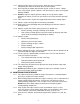
ALIGN THIS EDGE WITH A VERTICAL SURFACE (TREE, BUILDING, FENCE POST, POLE ETC.) THI S IS A THIS IS 20 ° S LOP E 10° SL OPE A 1 5 ° SL OPE THIS IS A THIS IS A 5° SLOPE FOLD ALONG APPROPRIATE LINE EXAMPLE: COMPARE SLOPE WITH FOLDED EDGE.
SEE EXMARK’S COMPLETE LINE OF PRODUCTS FOR TURF CARE LAZER Z™ LAZER Z™ HP TURF RANGER® TURF TRACER® TURF TRACER® HP VIKING HYDRO METRO™ METRO™ HP SELF STEERING SULKY GRASS CATCHER MICRO-MULCH ™ ACCESSORY ©1997,1998, 1999 EXMARK MFG. CO. INC. INDUSTRIAL PARK BOX 808 BEATRICE, NE 68310 ALL RIGHTS RESERVED PART NO. 850662 (402) 223-6300 FAX (402) 223-5489 PRINTED IN U.S.A. ® M F G . C O . IN C .