QUEST SP MODELS ® For Serial Nos. 850,000 & Higher Part No. 4500-582 Rev.
WARNING CALIFORNIA Proposition 65 Warning The engine exhaust from this product contains chemicals known to the State of California to cause cancer, birth defects, or other reproductive harm. Important: The engine in this product is not equipped with a spark arrester muffler. It is a violation of California Public Resource Code (CPRC) Section 4442 to use or operate this engine on any forest-covered, brush-covered, or grass-covered land as defined in CPRC 4126.
Introduction CONGRATULATIONS on the purchase of your Exmark Mower. This product has been carefully designed and manufactured to give you a maximum amount of dependability and years of trouble-free operation. This manual contains operating, maintenance, adjustment, and safety instructions for your Exmark mower. BEFORE OPERATING YOUR MOWER, CAREFULLY READ THIS MANUAL IN ITS ENTIRETY.
Contents Electric Clutch Adjustment............................ 39 Cleaning ........................................................... 41 Clean Engine and Exhaust System Area .......................................................... 41 Remove Engine Shrouds and Clean Cooling Fins........................................................... 41 Clean Hydro Fan Cooling Fins ....................... 41 Clean Debris From Machine .......................... 41 Clean Grass Build-Up Under Deck ................
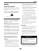
Safety Safety • Never let children or untrained people operate or service the equipment. Local regulations may restrict the age of the operator. Safety Alert Symbol • Only adults and mature teenagers should operate a mower, and even mature teenagers should have adult supervision. Be sure a teenager: This Safety Alert Symbol (Figure 2) is used both in this manual and on the machine to identify important safety messages which must be followed to avoid accidents. 1.
Safety thrown by the machine and may cause personal injury to the operator or bystanders. DANGER In certain conditions during fueling, static electricity can be released causing a spark which can ignite gasoline vapors. A fire or explosion from gasoline can burn you and others and cause property damage. DANGER In certain conditions gasoline is extremely flammable and vapors are explosive. A fire or explosion from gasoline can burn you, others, and cause property damage.
Safety functioning properly. Do Not operate unless they are functioning properly. – Before checking, cleaning or working on the mower. – After striking a foreign object or abnormal vibration occurs (inspect the mower for damage and make repairs before restarting and operating the mower). – Before clearing blockages. – Whenever you leave the mower. • Stop engine, wait for all moving parts to stop, and engage parking brake: – Before refueling. – Before dumping the grass catcher.
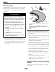
Safety Slope Operation Use Extreme caution when mowing and/or turning on slopes as loss of traction and/or tip-over could occur. The operator is responsible for safe operation on slopes. DANGER Operating on wet grass or steep slopes can cause sliding and loss of control. Wheels dropping over edges, ditches, steep banks, or water can cause rollovers, which may result in serious injury, death or drowning. Figure 3 • Do Not mow slopes when grass is wet. 1.
Safety Towing WARNING • Use for towing only if equipped with an Exmark hitch kit. Do Not attach towed equipment except at the hitch point. • Follow Exmark’s recommendation for weight limits for towed equipment and towing on slopes. This information can be found in the hitch kit instruction sheet and on the decal. • Never allow children or others in or on towed equipment. • On slopes, the weight of the towed equipment may cause loss of traction and loss of control.
Safety • Check for proper brake operation frequently. Adjust and service as required. WARNING Removing standard original equipment parts, or using non-Exmark replacement parts and accessories may alter the warranty, traction, and safety of the machine. Failure to use original Exmark parts could cause serious injury or death. • Charge batteries in an open well ventilated area, away from spark and flames. Unplug charger before connecting or disconnecting from battery.
Safety Safety and Instructional Decals • Keep all safety signs legible. Remove all grease, dirt and debris from safety signs and instructional labels. • Replace all worn, damaged, or missing safety signs. • When replacement components are installed, be sure that current safety signs are affixed to the replaced components. • If an attachment or accessory has been installed, make sure current safety signs are visible.
Safety 103-3270 109-6014 109-9173 1. Parking brake 2. Fast 3. Slow 4. Neutral 5. Reverse 6. Machine speed 107-2102 109-9182 1. Machine speed 2. Fast 3. Slow 109-3148 12 4. Neutral 5.
Safety 112-8651 1. 2. 3. 4. 5. 6. Interval Power Take-off (PTO) Parking brake Neutral Operator presence switch Battery 116-1121 1. Rotate the drive release knob to loosen, slide the knob, and tighten 2. Push the machine 116-1496 116-1118 1. Height of cut 116-2577 1. Fast 2. Continuous variable setting 3. Slow 116-1119 4. Choke-on 5.
Safety PTO Switch Symbols 1. PTO–disengage 2. PTO–engage 109-6016 1. Read the instructions before servicing or performing maintenance 2. Time interval 4. Refer to the Operator’s manual for grease instructions 5. Check hydraulic oil level and refer to the Operator’s manual for further instructions 6. Check tire pressure 3.
Safety 116-2834 15
Specifications Specifications Model Numbers Serial Nos: 850,000 and Higher QSP20BV443; QSP20KAS443; QSP20KAS483; QSP20KAX443; QSP22KAS523 Systems Safety Interlock System • LCD indicators appear for the PTO, park brake, drive levers, and operator presence in the message display on the RH control panel. • PTO must be disengaged, brake engaged, and motion control levers out (neutral lock) to start engine. (It is not necessary for the operator to be in the seat to start the engine.
Specifications • Mounting: Hinged to tilt up for access to hydraulic pumps, battery and other components. Held in tilted position with lanyard. Adjustable fore and aft. • Armrests: Standard–foam padded flip-up adjustable height armrests. • Seat Safety Switch: Incorporated into the Safety Interlock System. – 52 inch Deck: 18.00 inches (45.7 cm) – (3 ea.) • Blade Spindles: Solid steel spindles with no maintenance bearings. • Deck Drive: Electric clutch mounted on vertical engine shaft.
Product Overview Tread Width: (Center to Center of Tires, Widthwise) 44 inch Deck 48 inch Deck 52 inch Deck Drive Wheels 36.0 inches (91 cm) 36.0 inches (91 cm) 37.2 inches (96 cm) Caster Wheels 26.7 inches (68 cm) 33.5 inches (85 cm) 33.5 inches (85 cm) Product Overview Wheel Base: (Center of Caster Tire to Center of Drive Tire) 44 inch 48 & 52 inch 49.6 inches (126 cm) 48.
Operation Operation position. Do Not run a warm engine with choke in the “ON” position. Note: Determine the left and right sides of the machine from the normal operating position. Controls Motion Control Levers The motion control levers located on each side of the console control the forward and reverse motion of the machine. Moving the levers forward or backward turns the wheel on the same side forward or reverse respectively. Wheel speed is proportional to the amount the lever is moved.
Operation The ignition switch is used to start and stop the engine. The switch has three positions “OFF”, “ON” and “START”. Insert key into switch and rotate clockwise to the “ON” position. Rotate clockwise to the next position to engage the starter (key must be held against spring pressure in this position). Allow the key to return to the “on” position immediately after the engine starts.
Operation The LCD indicator will appear when the PTO switch is disengaged (see Figure 8). Deck Lift Pedal Located at the right front corner of the floor pan (see Figure 10). Push the pedal forward with your foot to raise the cutting deck. Allow the pedal to move rearward to lower the cutting deck to the cut height that has been set. Figure 9 1. 2. 3. 4. 5. 6. 7.
Operation than 10% ethanol, premium gasoline, or white gas because the fuel system could be damaged. Do Not add oil to gasoline. Do Not overfill fuel tank. Fill the fuel tank to the bottom of the filler neck. The empty space in the tank allows gasoline to expand. Overfilling may result in fuel leakage or damage to the engine or emission system (if equipped). Make sure you understand the controls, their locations, their functions, and their safety requirements.
Operation Open the Fuel Shut-Off Valve DANGER The fuel shut off valve is located behind and below the seat. Rotate the valve and align with the fuel line to open. An uncovered discharge opening will allow objects to be thrown in an operator’s or bystander’s direction. Also, contact with the blade could occur. Thrown objects or blade contact can cause serious injury or death. Starting the Engine 1. Move the motion control levers out to the neutral lock position.
Operation Driving the Machine Driving Forward 1. Release the parking brake. 2. Move the motion control levers inward to the center to the neutral position. 3. To move forward in a straight line, move both levers forward with equal pressure. CAUTION Machine can spin very rapidly by positioning one lever too much ahead of the other. Operator may lose control of the machine, which may cause damage to the machine or injury.
Operation 3. Raise the deck to the transport position, 5 inch (12.7 cm), by pushing the foot actuated lever forward. The spring loaded transport pin will automatically engage and will click into place. mm) clearance to the ground to minimize gouging and roller wear or damage. Note: When changing the cutting height positions, always come to a complete stop and disengage the PTO. Figure 16 For cutting heights above 3.5 inches (90 mm) use the bottom hole.
Operation Transporting WARNING Loading a unit on a trailer or truck increases the possibility of backward tip-over. Backward tip-over could cause serious injury or death. Transporting a Unit Use a heavy-duty trailer or truck to transport the machine. Lock brake and block wheels. Securely fasten the machine to the trailer or truck with straps, chains, cable, or ropes. Be sure that the trailer or truck has all necessary lighting and marking as required by law. Secure a trailer with a safety chain.
Operation Important: Do Not attempt to turn the unit while on the ramp, you may lose control and drive off the side. Avoid sudden acceleration when driving up a ramp and sudden deceleration when backing down a ramp. Both maneuvers can cause the unit to tip backward.
Maintenance Maintenance Note: Determine the left and right sides of the machine from the normal operating position. WARNING WARNING While maintenance or adjustments are being made, someone could start the engine. Accidental starting of the engine could seriously injure you or other bystanders. The engine can become very hot. Touching a hot engine can cause severe burns. Allow the engine to cool completely before service or making repairs around the engine area.
Maintenance Periodic Maintenance the battery voltage will be displayed in the area where the hours are normally displayed. Locate the voltage reading of the battery in the table and charge the battery for the recommended time interval to bring the charge up to a full charge of 12.6 volts or greater.
Maintenance DANGER Jump starting a weak battery that is cracked, frozen, has low electrolyte level, or an open/shorted battery cell, can cause an explosion resulting in serious personal injury. Do Not jump start a weak battery if these conditions exist. 2. Make sure the booster is a good and fully charged lead acid battery at 12.6 volts or greater. Use properly sized jumper cables (4 to 6 AWG) with short lengths to reduce voltage drop between systems.
Maintenance motion control levers moved out in the neutral lock position. The operator does not need to be in the seat to start the engine. Try to start with operator in seat, parking brake disengaged, PTO disengaged and motion control levers in the neutral lock position - starter must not crank. Figure 19 1. 2. 3. 4. Try to start with operator in seat, parking brake engaged, PTO engaged and motion control levers in the neutral lock position - starter must not crank.
Maintenance Check Rollover Protection System (Roll Bar) Knobs See the Engine Owner’s Manual for additional information.) 1. Stop engine, wait for all moving parts to stop, and remove key. Engage parking brake. 2. See the Engine Owner’s Manual for maintenance instructions. Service Interval: Before each use or daily Check that both the mounting hardware and the knobs are in good working condition. Make sure the knobs are fully engaged with the ROPS in the raised position.
Maintenance Change Fuel Filter Service Interval: Every 100 hours A fuel filter is installed between the fuel tank and the engine. Replace when necessary. Replacement Filters Figure 21 1. Engine 2.
Maintenance Hydro Oil Change Interval Exmark Premium Hydro Oil (Preferred) 500 Hours Mobil 1 15W50 250 Hours WARNING Engine must be running and drive wheels must be turning so adjustments can be performed. Contact with moving parts or hot surfaces may cause personal injury. Torque plugs to 180 in-lb (244 N-m). Continue to add oil until it reaches the FULL COLD line on the expansion reservoir. Keep fingers, hands, and clothing clear of rotating components and hot surfaces. A.
Maintenance Adjustments 2. Wait for muffler to cool. 3. If any breaks in the screen or welds are observed, replace arrester. Note: Disengage PTO, shut off engine, wait for all moving parts to stop, engage parking brake, and remove key before servicing, cleaning, or making any adjustments to the unit. 4. If plugging of the screen is observed, remove arrester and shake loose particles out of the arrester and clean screen with a wire brush (soak in solvent if necessary).
Maintenance 9. Carefully rotate the blades side to side (Figure 23 and Figure 24). 10. Loosen the leveling adjust locking nuts (item 1 Figure 25) on all four corners so that the deck is sitting securely on all four blocks. Make sure that the slack is removed from the deck hangers and the deck lift foot lever is pushed back against the stop, then tighten the four leveling adjust locking nuts. Figure 23 48 and 52 Inch Decks 1. Blades side to side 2. Measure here Figure 25 1. Leveling adjust locking nuts 2.
Maintenance Checking the Tire Pressure in Drive System Maintenance section. 5. Check and adjust the side-to-side blade level if you have not checked the setting; refer to Deck Leveling. 6. Set the height-of-cut lever to the 3 inch (76 mm) position. Place two “B” thick blocks (see Block Height and Rake Table in Deck Leveling) under the rear edge of the cutting deck skirt; one on each side of the cutting deck.
Maintenance or when a brake component has been removed or replaced. • Adjusting the Brake to Engage: Shorten the linkage by turning the yoke clockwise. 1. Drive the machine onto a level surface. • Adjusting the Brake to Disengage: Lengthen the linkage by turning the yoke counterclockwise. 2. Disengage the blade control switch (PTO), move the motion control levers to the neutral locked position and set the parking brake. 8. Reinstall the clevis pin and hair pin and tighten down the jam nut.
Maintenance with heavier operators and on rough terrain. Fewer springs should be used with lighter operators and when mowing smooth, well established lawns. Always keep the number of springs on the left and right side the same when adding and removing springs. 1. Loosen the upper bolt holding the control lever to the control arm shaft. 2. Loosen the lower bolt just enough to pivot the control lever fore or aft Figure 30. Tighten both bolts to secure the control in the new position. 3.
Maintenance as shown. (Due to the way the rotor and armature faces wear (peaks and valleys) it is sometimes difficult to measure the true gap.) the machine to cool completely before starting these instructions. 2. Using a pneumatic line, blow out any debris from under the brake pole and around the brake spacers. 3. Check the condition of the wire harness leads, connectors, and terminals. Clean or repair as necessary. G011733 4.
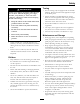
Maintenance Cleaning Removing debris from the hydro fan cooling fins will allow the hydro system to run cooler and improve the life of the hydro system. 1. Stop engine, wait for all moving parts to stop, and remove key. Engage parking brake. 2. Lift the seat to access the LH and RH hydro drive area. 3. Remove accumulated debris from the hydro fan cooling fins. Clean Engine and Exhaust System Area Service Interval: Before each use or daily (May be required more often in dry or dirty conditions.
Maintenance Waste Disposal Motor Oil Disposal Engine oil and hydraulic oil are both pollutants to the environment. Dispose of used oil at a certified recycling center or according to your state and local regulations. Battery Disposal DANGER Battery electrolyte contains sulfuric acid, which is poisonous and can cause severe burns. Swallowing electrolyte can be fatal or if it touches skin can cause severe burns.
Troubleshooting Troubleshooting Important: It is essential that all operator safety mechanisms be connected and in proper operating condition prior to mower use. When a problem occurs, do not overlook the simple causes. For example: starting problems could be caused by an empty fuel tank. The following table lists some of the common causes of trouble. Do not attempt to service or replace major items or any items that call for special timing of adjustment procedures (such as valves, governor, etc.).
Troubleshooting Problem Engine loses power Possible Cause Corrective Action 1. Engine load is excessive 1. Reduce the ground speed. 2. Air cleaner is dirty. 3. Oil level in the crankcase is low. 4. Cooling fins and air passages for the engine are plugged. 5. Dirt in fuel filter. 6. Dirt, water, or stale fuel is in the fuel system. 2. Clean or replace the air cleaner element. 3. Add oil to the crankcase. 4. Remove the obstructions from the cooling fins and air passages. 5. Replace the fuel filter. 6.
CONNECTIONS ACCESSORY BATTERY IGNITION START RECTIFIER TERMINAL TERMINAL A TERMINAL B TERMINAL I TERMINAL S TERMINAL R TERMINAL R TERMINAL A B+R+I+S B+R+I+A NONE CIRCUIT “MAKE” IGNITION SWITCH TERMINAL B TERMINAL S TERMINAL I 3. START 2. RUN 1.
5 6 SW2 PTO SW (IN OFF POSITION) BK BK BN BN BN 7 ENGINE GND A PTO CLUTCH B 4 BN VIO F3 10A 8 PK 1 2 BK 5 BN 8 T 9 Y 7 VIO SW4 LH NEUT SWITCH (IN NEUT LOCK) LT GN PTO PK PK BK NEUTRAL PK 4 FUEL SOLENOID SEAT BRAKE 2 SW5 RH NEUT SWITCH (IN NEUT LOCK) GROUND OR 8 10 OR W 1 T PK ENGINE GRD KEY A MAGNETO OPTIONAL ACCESSORIES CONNECTOR F4 6 R 7 GN 3 B+ 46 START RELAY BN M1 HOUR METER SW6 SEAT SW (W/OPER IN SEAT) OR PK OR OR I 5 A 4 R R B 2 1
Quest SP Turf Equipment 1 Year Limited Commercial Warranty 4 Year or 400 Hours Limited Consumer Warranty General Warranty Conditions and Products Covered Exmark Mfg. Co. Inc. and its affiliate, Exmark Warranty Company, pursuant to an agreement between them, jointly warrant on the terms and conditions herein, that we will repair, replace or adjust any part on these products and found by us (in the exercise of our reasonable discretion) to be defective in factory materials or workmanship.
Notes: 48
Service Record Date: Description of Work Done: 49 Service Done By:
G011841 Figure 37 This page may be copied for personal use. 1. The maximum slope you can safely operate the machine on is 15 degrees. Use the slope indicator to determine the degree of slope of hills before operating. Do Not operate this machine on a slope greater than 15 degrees. Fold along the appropriate line to match the recommended slope. 2. Align this edge with a vertical surface, a tree, building, fence pole, etc. 3. Example of how to compare slope with folded edge.
SEE EXMARK’S COMPLETE LINE OF ACCESSORIES AND OPTIONS MID-MOUNT RIDING ACCESSORIES AND OPTIONS CUSTOM RIDE SEAT SUSPENSION SYSTEM OPERATOR CONTROLLED DISCHARGE FULL SUSPENSION SEAT ROLL OVER PROTECTION SYSTEM (ROPS) DECK LIFT ASSIST KIT SUN SHADE HITCH KIT TRASH CONTAINER LIGHT KIT TURF STRIPER 12V POWER PORT ULTRA VAC COLLECTION SYSTEM MICRO-MULCH SYSTEM ULTRA VAC QUICK DISPOSAL SYSTEM OUT-FRONT RIDING ACCESSORIES AND OPTIONS CUSTOM RIDE SEAT SUSPENSION SYSTEM SNOW BLADE DUAL-TAIL WHEEL SN