For Serial Nos. 540,000 & Higher Part No.
WARNING POTENTIAL HAZARD ♦ This product is a piece of power equipment. WHAT CAN HAPPEN ♦ Failure to follow safe operating practices can result in serious operator injury or even death. HOW TO AVOID THE HAZARD ♦ Keep all shields, guards, and safety devices (especially the grass discharge system) in place and in proper working condition. ♦ Stop engine and wait for all moving parts to stop. Remove spark plug wire(s) or remove key before adjusting, servicing, or performing maintenance.
EXMARK PARTS PLUS® PROGRAM EFFECTIVE DATE: September 1, 1995 Program If your Exmark dealer does not have the Exmark part in stock, Exmark will get the parts to the dealer the next business day or the part will be FREE* Guaranteed!! How the Program Works 1. If dealer does not have part in stock for a "down" unit at the time of request by customer, the dealer contacts his distributor by 1:00 p.m., local time, and requests Exmark Parts Plus® shipment of six (6) line items or less. 2.
CONGRATULATIONS on the purchase of your Exmark Mower. This product has been carefully designed and manufactured to give you a maximum amount of dependability and years of trouble-free operation. OPERATOR'S MANUAL This manual contains assembly, operating, maintenance, adjustment, and safety instructions for your Exmark mower. BEFORE OPERATING YOUR MOWER, CAREFULLY READ THIS MANUAL IN ITS ENTIRETY.
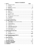
TABLE OF CONTENTS 1. SAFETY 1.1 1.2 1.3 1.4 1.5 1.6 PAGE Safety Alert Symbol ....................................................................................... 1 Training ......................................................................................................... 1 Preparation................................................................................................. 1-3 Operation ...................................................................................................
1. SAFETY 1.1 SAFETY ALERT SYMBOL This SAFETY ALERT SYMBOL is used both in this manual and on the machine to identify important safety messages which must be followed to avoid accidents. This symbol means: ATTENTION! BECOME ALERT! YOUR SAFETY IS INVOLVED! The safety alert symbol appears above information which alerts you to unsafe actions or situations and will be followed by the word DANGER, WARNING, or CAUTION. DANGER: White lettering / Red background.
1.3.4 Thoroughly inspect the area where the equipment is to be used and remove all stones, sticks, wires, bones, and other foreign objects which may damage the equipment or cause personal injury to the operator or bystanders. WARNING POTENTIAL HAZARD ♦ Engine exhaust contains carbon monoxide, which is an odorless deadly poison. WHAT CAN HAPPEN ♦ Carbon monoxide can kill you. HOW TO AVOID THE HAZARD ♦ Do not run engine indoors or in a small confined area where dangerous carbon monoxide fumes can collect.
DANGER POTENTIAL HAZARD ♦ In certain conditions gasoline is extremely flammable and highly explosive. WHAT CAN HAPPEN ♦ A static charge can ignite gasoline vapors. A fire or explosion from gasoline can burn you, others, and cause property damage. HOW TO AVOID THE HAZARD ♦ Purchase and store gasoline only in an approved container. ♦ Always place gasoline containers on the ground away from your vehicle before filling.
1.4 OPERATION Although hazard control and accident prevention are partially dependent upon the design and configuration of the equipment, these factors are also dependent upon the awareness, concern, prudence, and proper training of the personnel involved in the operation, transport, maintenance, and storage of the equipment. It is essential that all Operator Safety Mechanisms be connected and in operating condition prior to use for mowing.
DANGER POTENTIAL HAZARD ♦ Mowing on wet grass or steep slopes can cause sliding and loss of control. WHAT CAN HAPPEN ♦ Wheels dropping over edges, ditches, steep banks, or water can cause rollovers, which may result in serious injury, death or drowning. HOW TO AVOID THE HAZARD ♦ Do not mow slopes when grass is wet. ♦ Do not mow near drop-offs or near water. ♦ Do not mow slopes greater than 15 degrees. ♦ Reduce speed and use extreme caution on slopes. ♦ Avoid sudden turns or rapid speed changes.
WARNING POTENTIAL HAZARD ♦ There is no rollover protection when the roll bar is down. WHAT CAN HAPPEN ♦ Wheels dropping over edges, ditches, steep banks, or water can cause rollovers, which may result in serious injury, death or drowning. HOW TO AVOID THE HAZARD ♦ Keep the roll bar in the raised and locked position and use seat belt. ♦ Lower the roll bar only when absolutely necessary. ♦ Do not wear seat belt when the roll bar is down. ♦ Drive slowly and carefully.
1.4.17 1.4.18 1.4.19 1.4.20 1.4.21 Do Not mow with the discharge deflector raised, removed or altered unless there is a grass collection system or mulch kit in place and working properly. Be aware of the mower discharge and direct discharge away from others. Do Not operate mower under the influence of alcohol or drugs. Use extra care when approaching blind corners, shrubs, trees, or other objects that may obscure vision.
WARNING POTENTIAL HAZARD ♦ Hydraulic fluid escaping under pressure can penetrate skin and cause injury. WHAT CAN HAPPEN ♦ Fluid accidentally injected into the skin must be surgically removed within a few hours by a doctor familiar with this form of injury or gangrene may result. HOW TO AVOID THE HAZARD ♦ Make sure all hydraulic fluid hoses and lines are in good condition an all hydraulic connections and fittings are tight before applying pressure to hydraulic system.
PART NO. 103-3979 LOCATION: RH Side of Console PART NO. 103-3794 LOCATION: LH Side of Console PART NO. 1-513742 LOCATION: Top of Mower Deck Belt Shields, Left and Right Sides All units except Kohler EFI PART NO. 103-4474 LOCATION: Top Front of RH Fuel Tank Kohler EFI units PART NO. 103-5456 LOCATION: Top Front of RH Fuel Tank PART NO. 98-5954 LOCATION: Under Mower Deck Belt Shield(s) PART NO. 1-403005 LOCATION: Left and Right Corners of Mower Deck PART NO.
PART NO. 1-643339 LOCATION: Top of Right Engine Baffle PART NO. 1-303508 LOCATION: RH Side on Top Rear of Mower Deck PART NO. 1-633702 LOCATION: Bottom Side of Floor Pan PART NO. 103-9255 LOCATION: Top of console DO NOT OPERATE WITHOUT GUARD IN PLACE.1-513748 PART NO. 1-513748 LOCATIONS: Bottom Side of Floorpan Kohler EFI Units Only PART NO. 103-2750 LOCATION: Panel behind LH Fuel Tank PART NO. 103-0368 LOCATION: Rubber Heat Shield Flap behind Seat PART NO.
PART NO. 1-523552 LOCATION: Top of Hydraulic Reservoir, Under the Seat Kohler EFI Units Only PART NO. 103-0261 LOCATION: RH Front of Console Type A Anti-scalp Rollers Only – See Figure 11 PART NO. 1-323540 LOCATION: Left Rear Corner Top of Mower Deck All Units except Kohler EFI PART NO. 103-0262 LOCATION: RH Front of Console PART NO. 103-3270 LOCATION: RH Air Cleaner Mount Plate All Units except Kohler EFI PART NO. 103-4930 LOCATION: Right of Choke Control on RH Fuel Tank PART NO.
2. SPECIFICATIONS 2.1 MODEL NUMBER: Serial Nos. 510,000 and Higher LZ25KC524; LZ27KC524; LZ23KC604; LZ25KC604; LZ27KC604; LZ28KC604; LZ27KC724; LZ28KC724 2.2 ENGINE: 2.2.1 2.2.2 Engine Specifications: See your Engine Owner’s Manual RPM: Full Speed: 3750 RPM (No Load) Idle: 1500 RPM 2.3 FUEL SYSTEM 2.3.1 2.3.2 2.3.3 2.3.4 2.3.5 Capacity: 13.5 gal. (51 L.) Type of Fuel: Regular unleaded gasoline, 87 octane or higher Fuel Filter: All units except Kohler EFI: In-line 15 Micron Kohler P/N 2405002.
2.5.5 Deck Lift Assist Lever: Foot pedal that assists in raising the deck. 2.6 SEAT 2.6.1 Type: All units except Kohler EFI: Standard seat with high back, foam padded (internal suspension) and armrests. Kohler EFI units: Standard seat with high back, foam padded (internal suspension), armrests and a custom ride suspension system. Optional seat accessories: • Custom ride suspension system to enhance Standard Seat.
2.9.5 Deck Drive: Electric clutch mounted on horizontal engine shaft. “B” Section belt (with self-tensioning idler) from electric clutch to transfer shaft mounted on deck. Blades are driven by one “B” Section belt (w/self-tensioning idler) from transfer shaft on deck to blade spindles. 2.9.6 Deck: Full floating deck is attached to out-front support frame. Six anti-scalp rollers provide maximum turf protection. Deck design allows for bagging, mulching or side discharge. Deck Depth: 52” Deck: 5.5” (14.
Wheel Lug Nuts .............................................................90-95 ft-lbs. (122-129 N-m) Wheel Motor Mounting Bolts............................................72-77 ft-lbs. (98-104 N-m) Wheel Hub Slotted Nut ..............................................minimum125 ft-lbs. (169 N-m) Rollover Protection System (Roll Bar) Mounting Bolts .......30-35 ft-lbs. (41-47 N-m) Clutch Retaining Bolt (secured with threadlocker)..............55-60 ft-lbs. (75-81 N-m) 3. ASSEMBLY INSTRUCTIONS 3.
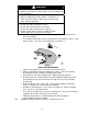
FIGURE 2 LOWER ROLL BAR INSTALLATION 3.2.5 Install the upper u-shaped section of the roll bar. (Reference Figure 3 for alignment and installation instructions below): a) Locate the latch pin assemblies (pin and hairpin connected with a lanyard). b) Install a 1/2-13 x 3 1/4 capscrew in the washer on the lanyard of each pin assembly. Note: Make sure the bent tab in the washer points toward the head of the capscrew.
FIGURE 3 UPPER ROLL BAR INSTALLATION 3.3 SERVICE BATTERY WARNING: Battery posts, terminals, and related accessories contain lead compounds, chemicals known to the State of California to cause cancer and reproductive harm. Wash hands after handling. The machine is shipped with a filled lead acid battery. 3.3.1 Unhook seat latch and tilt seat up to gain access to the battery.
CAUTION POTENTIAL HAZARD ♦ If the ignition is in the “ON” position there is potential for sparks and engagement of components. WHAT CAN HAPPEN ♦ Sparks could cause an explosion or moving parts could accidentally engage causing personal injury. HOW TO AVOID THE HAZARD ♦ Be sure ignition switch is in the “OFF” position before charging the battery. 3.3.3 Connect the negative battery cables.
e) Secure air cleaner by tightening the tensioning bolt and spring assembly until ends of clamp are approximately ½” (12.7 mm) apart. 3.8 INSTALL MOTION CONTROL LEVERS. 3.8.1 a) Loosen and remove the two (2) 3/8” x 1” bolts and spring disc washers which attach the motion control levers to the control arm shafts for shipping and the two (2) 3/8” x 1” bolts and spring disc washers which are screwed into the control arm shafts.
NOTE: The baffle is labeled “HOT” and “COLD”. The oil level varies with the temperature of the oil. The “HOT” level shows the level of oil when it is at 225°F (107°C). The “COLD” level shows the level of the oil when it is at 75°F (24°C). Fill to the appropriate level depending upon the temperature of the oil. For example: If the oil is about 150° F (65°C). Fill to halfway between the “HOT” and “COLD” levels. If the oil is at room temperature (about 75° F (24°C)), fill only to the “COLD” level. 4.
CAUTION POTENTIAL HAZARD ♦ Machine can spin very rapidly by positioning one lever too much ahead of the other. WHAT CAN HAPPEN ♦ Operator may lose control of the machine, which may cause damage to the machine or injury. HOW TO AVOID THE HAZARD ♦ Use caution when making turns. ♦ Slow the machine down before making sharp turns. 4.1.3 Tracking Adjustment Knob : Located under the seat on the RH pump control link.
NOTE: This switch is not a low oil sensor and will not alert the operator if the engine oil is low. 4.1.10 Fuel Shut-Off Valve: Located directly below right side of console, next to cubby. The fuel shut-off valve is used to shut off the fuel when the machine will not be used for a few days, during transport to and from the job site, and when parked inside a building. The valve has three positions, each position made in 1/4 turn increments.
4.3 OPERATING INSTRUCTIONS 4.3.1 Operate units with the roll bar in the raised and locked position and use seat belt. There is no rollover protection when the roll bar is down. If it is necessary to lower roll bar do not wear the seat belt. Raise the roll bar as soon as clearance permits. 4.3.2 Open fuel shut-off valve (left or right tank). 4.3.3 Starting Engine: Brake must be engaged, motion control levers out (neutral lock position) and PTO switch “OFF” to start engine.
IMPORTANT: Operator must be in seat before the PTO can be engaged. Set throttle to "midway" position. Pull outward on the switch to the “ROTATE” position. Accelerate to full throttle to begin mowing. 4.3.5 Stopping PTO: Set throttle to the “midway” position. Push in on the switch to the “STOP” position stopping the PTO. 4.3.6 Stopping Engine: Bring unit to a full stop. Disengage the PTO, move motion control levers out to the neutral lock position and set parking brake.
WARNING POTENTIAL HAZARD ♦ Loading a unit on a trailer or truck increases the possibility of backward tip-over. WHAT CAN HAPPEN ♦ Backward tip-over of the unit could cause serious injury or death. HOW TO AVOID THE HAZARD ♦ Use extreme caution when operating a unit on a ramp. ♦ Use only a single, full width ramp; DO NOT use individual ramps for each side of the unit. ♦ If individual ramps must be used, use enough ramps to create an unbroken ramp surface wider than the unit.
WARNING POTENTIAL HAZARD ♦ The engine can become very hot. WHAT CAN HAPPEN ♦ Touching a hot engine can cause severe burns. HOW TO AVOID THE HAZARD ♦ Allow the engine to cool completely before service or making repairs around the engine area. 5.1 PERIODIC MAINTENANCE 5.1.1 Check engine oil level: Service Interval: Daily a) Stop engine and wait for all moving parts to stop. Make sure unit is on a level surface. b) Check with engine cold. c) Clean area around dipstick. Remove dipstick and wipe oil off.
5.1.3 Clean engine cooling system: Service Interval: Daily or more often in dry conditions CAUTION POTENTIAL HAZARD ♦ Excessive debris and damaged or missing rubber baffles can cause the engine and hydraulic system to overheat. WHAT CAN HAPPEN ♦ Excessive debris around the engine cooling air intake and inside of the pump drive belt compartment can create a fire hazard. HOW TO AVOID THE HAZARD ♦ Clean all debris from inside of pump drive belt compartment daily.
d) Re-install the blades (if they were removed) in the following order (See Figure 7): 1) Install bushing through blade with bushing flange on bottom (grass) side of blade. 2) Install bushing/blade combo into spindle. 3) Install blade bolt and spring disc washer. Be sure the spring disc washer cone is installed towards the bolt head. Place a block of wood between front or rear baffles and the blade then torque the blade bolts to 55-60 ft-lbs. (75-81 N-m).
Try to start with operator in seat, parking brake engaged, PTO engaged and motion control levers in the neutral lock position - starter must not crank. Try to start with operator in seat, parking brake engaged, PTO disengaged, and the left motion control lever in, starter must not crank, repeat again with the right lever in, then with both levers in starter must not crank. b) Check the kill circuits.
5.1.10 Check Spark Arrester Kohler EFI engines only: Service Interval: 50 hours WARNING POTENTIAL HAZARD ♦ Hot exhaust system components may ignite gasoline vapors even after the engine is stopped. ♦ Hot particles exhausted during engine operation may ignite flammable materials. WHAT CAN HAPPEN ♦ Fire may result in personal injury or property damage. HOW TO AVOID THE HAZARD ♦ Do NOT refuel or run engine unless spark arrester is installed.
5.1.13 Check tire pressures: Service Interval: 40 hrs. a) b) c) d) Stop engine, wait for all moving parts to stop, and remove key. Check tire pressure in drive tires. Inflate drive tires to 13 psi (90 kPa). Caster tires do not need to be inflated. NOTE: Do not add any type of tire liner or foam fill material to the tires. Excessive loads created by foam filled tires may cause failures to the hydro drive system, frame, and other components. Foam filling tires will void the warranty. 5.1.
c) Lubricate front caster pivots once a year. Remove hex plug and cap. Thread grease zerk in hole and pump with grease until it oozes out around top bearing. Remove grease zerk and thread plug back in. Place cap back on. 5.1.16 Lubricate caster wheel hubs: Service Interval: Once Yearly a) Stop engine, wait for all moving parts to stop, and remove key. b) Remove caster wheel from caster forks. c) d) Remove seal guards from the wheel hub.
5.1.18 Lubricate brake handle pivot: Service Interval: 160 hrs. a) Stop engine, wait for all moving parts to stop, and remove key. b) Lubricate bronze bushings on brake handle pivot with a spray type lubricant or light oil. 5.1.19 Lubricate brake rod bushings: Service Interval: 160 hrs. a) Stop engine, wait for all moving parts to stop, and remove key. b) Unhook seat latch and tilt seat up. c) 5.1.
Note: For Kohler EFI units use only high pressure clamps and SAE R7 or R9 hose available from Exmark or Kohler. Clamps require special pliers P/N 1643394 (Oetiker P/N 14100118 or Kohler P/N 2445505) for installation.
b) Allow the engine to cool completely. c) Connect the black tester hose from the Kohler pressure gauge to the test valve in the fuel rail. d) Route the clear hose into a portable gasoline container and depress the button on the tester relief valve. 5.1.25 Change hydraulic system filter: Service Interval: After First 250 hrs. Then yearly thereafter NOTE: Use only Exmark Part No. 1-513211 for summer use above 32° F (0°C) or Part No. 1-523541 for winter use below 32° F (0°C).
a) Pump drive sheave set screws. b) Square head setscrews on Hydro pump control arms. c) Sheave retaining bolt in the end of engine crankshaft. d) Caster wheel spacer nuts e) Fuel tank bulkhead fitting nuts. f) Cutter housing spindle nut. Adhesives such as “Loctite RC/609 or RC/680” or “Fel-Pro Pro-Lock Retaining I or Retaining II” are used on the following: a) 5.1.29 5.1.30 Fuel tank studs, where studs are inserted into tank.
g) Adjust anti-scalp rollers for Normal Operating Conditions. Place rollers in one of the positions shown in Figure 11. Rollers will maintain 3/4 in. (19 mm) clearance to the ground to minimize gouging and roller wear or damage. For Maximum Deck Flotation, place rollers one hole position lower. Rollers should maintain 1/4 in. (6.4 mm) clearance to ground. Do Not adjust rollers to support the deck.
h) Loosen the two (2) top chain bolts in slots in the rear deck lift arms. Loosen jam nuts and back off the socket head adjusting screws on the bottom of the arms until the chains are just loose. Turn the socket head adjusting screws in until slack is taken out of each chain. Tighten the jam nuts. Tighten the chain bolts in the deck lift arms making sure they don’t move while tightening.
Reposition the adjusting pulley to the bottom of the slot. NOTE: When installing a new belt, it is necessary to reposition the right adjusting pulley upward in the slot in order to position the center of the spring loaded pulley between the alignment holes. FIGURE 13 MULE DRIVE BELT ADJUSTMENT 5.2.5 5.2.6 5.2.7 Deck Belt Tension. a) The deck belt is tensioned by a self-tensioning idler, no adjustment is necessary.
FIGURE 14 BELT GUIDE POSITIONING 5.2.8 Brake Link Adjustment. Check to make sure brake is adjusted properly. a) Disengage brake lever (lever down). b) Measure the length of the spring. Measurement should be 2.75” (7.0 cm) between washers (see Figure 15). c) If adjustment is necessary, tighten the nut directly below the yoke and loosen the bottom nut (bottom one of the two tightened together) below the spring.
5.2.11 5.2.12 FIGURE 16 THROTTLE TENSION Electric Clutch Adjustment: No adjustment necessary. Reverse Indicator Adjustment: a) Stop engine, wait for all moving parts to stop, and remove key. b) c) Unhook seat latch and tilt seat forward. Begin with either the left or right motion control lever. Move lever to the neutral position and pull lever back until the clevis pin (on arm below pivot shaft) contacts the end of the slot (just beginning to put pressure on spring), See Figure 17.
5.2.13 Motion control linkage adjustment. WARNING POTENTIAL HAZARD ♦ Engine must be running and drive wheels must be turning so motion control adjustment can be performed. WHAT CAN HAPPEN ♦ Contact with moving parts or hot surfaces may cause personal injury. HOW TO AVOID THE HAZARD ♦ Keep fingers, hands, and clothing clear of rotating components and hot surfaces.
f) Start engine. Brake must be engaged and motion control levers out to start engine. Operator does not have to be in the seat because of the jumper wire being used. Run engine at full throttle and release brake. g) The reverse indicator spring must be correct before the following adjustments can be made. See Section 5.2.12. NOTE: The motion control lever needs to be in neutral while making any necessary adjustments.
6.2 BATTERY DISPOSAL DANGER POTENTIAL HAZARD ♦ Battery electrolyte contains sulfuric acid, which is poisonous and can cause severe burns WHAT CAN HAPPEN ♦ Swallowing electrolyte can be fatal or if it touches skin can cause severe burns. HOW TO AVOID THE HAZARD ♦ Wear safety glasses to shield eyes, and rubber gloves to protect skin and clothing when handling electrolyte. ♦ Do not swallow electrolyte. Federal law states that batteries should not be placed in the garbage.
g) h) i) Check that the spark plug wires are properly connected. Check for loose or faulty wiring connections. Check for corrosion at all wiring connections. Even minor corrosion may cause a faulty connection. Clean connector terminals thoroughly with electrical contact cleaner, apply dielectric grease and reconnect. NOTE: When disconnecting electrical connectors DO NOT pull on the wires to separate the connectors. NOTE: After carefully checking the above steps, attempt to start the engine.
8.
ELECTRICAL DIAGRAM – KOHLER EFI UNITS - 47 -
9.
10. 2-Year Limited Warranty Exmark Turf Equipment (For units purchased on or after October 1, 2004) Conditions and Products Covered Exmark Mfg. Co. Inc. and its affiliate, Exmark Warranty Company, pursuant to an agreement between them, jointly warrant on the terms and conditions herein, that we will repair, replace or adjust any part manufactured by Exmark and found by us (in the exercise of our reasonable discretion) to be defective in factory materials or workmanship for a period of two years.
- 50 -
SEE EXMARK’S COMPLETE LINE OF ACCESSORIES RIDING ACCESSORIES CUSTOM RIDE SEAT SUSPENSION SYSTEM DECK LIFT ASSIST KIT HITCH KIT LIGHT KIT MICRO-MULCH SYSTEM ROLL OVER PROTECTION SYSTEM (ROPS) SNOW BLADE SUN SHADE TRASH CONTAINER TURF STRIPER ULTRA VAC COLLECTION SYSTEM ULTRA VAC QUICK DISPOSAL SYSTEM WALK BEHIND ACCESSORIES GRASS CATCHER MICRO-MULCH SYSTEM STEERABLE SULKY SULKY HITCH KIT TURF STRIPER Check us out on the Web: www.exmark.