
User Guide


- 19 -
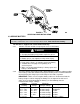
e) Secure air cleaner by tightening the tensioning bolt and spring assembly until
ends of clamp are approximately ½” (12.7 mm) apart.
3.8 INSTALL MOTION CONTROL LEVERS.
3.8.1 Loosen and remove the two (2) 3/8” x 1” bolts and spring disc washers which
attach the motion control levers to the control arm shafts for shipping and the
two (2) 3/8” x 1” bolts and spring disc washers which are screwed into the
control arm shafts.
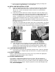
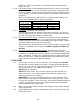
a) Install the left motion control lever onto the control arm shaft (See Figure 4) on
the left side of the console. Place the lever (with the mounting plate towards the
rear) on the outside of the control arm shaft and secure with the bolts and
washers. Position the lever so the bolts are in the center of the slots on the lever
mounting plate and tighten until snug. Repeat on opposite side of unit.
NOTE: There are two lever height options available. Place the levers in the top
two holes to increase height of the levers, or in the bottom two holes to decrease
the height of the levers.
If the levers do not align with each other, when in the neutral position, (See Figure
5) loosen the hardware and make the appropriate adjustment by sliding/tilting the
lever(s) forward or backward until properly aligned and tighten hardware.
FIGURE 4 FIGURE 5
CONTROL ARM SHAFT LEVER ALIGNMENT
b) If the ends of the levers hit against each other, while in the drive position
(levers rotated in as far as possible), make adjustments by moving the levers
outwards to the neutral lock position and carefully bend them outward. Move
them back to the drive position and check for clearance, repeat if necessary.
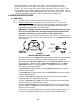
3.9 POSITION DISCHARGE CHUTE.
3.9.1 Loosen two (2) 5/16” nyloc nuts attaching discharge chute. Lower the discharge
chute into position. Retighten nyloc nuts until chute is snug but can pivot freely.
3.10 SERVICE ENGINE.
Engine is shipped with oil; check oil level and if necessary and fill to the appropriate
level with oil as specified in Engine Owner’s Manual.
3.11 SERVICE HYDRAULIC OIL
The machine is shipped with hydraulic oil in the reservoir. Run the machine for
approximately 15 minutes to allow any extra air to purge out of the hydraulic system.
Check hydraulic reservoir and if necessary fill the reservoir to the appropriate level with
Mobil 1 15W-50 synthetic motor oil. Replace hydraulic reservoir cap and tighten until
snug. Do not overtighten.
LEVERS IN
ALIGNMENT
MOUNT PLATE TO
THE REAR & OUTSIDE
OF ARM SHAFT
MOTION
CONTROL
LEVER