
User`s guide

INSTALLING THE TRAVELER HARDWARE
20
CONNECT THE TRAVELER INTERFACE
1 Make sure your computer and the Traveler are
switched off.
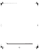
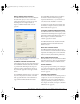
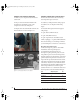
2 Plug one end of the Traveler FireWire cable
(included) into the FireWire socket on the
computer as shown below in Figure 4-1.
3 Plug the other end of the FireWire cable into the
Traveler I/O as shown below in Figure 4-1.
Figure 4-1: Connecting the Traveler to the computer.
CONNECT AUDIO INPUTS AND OUTPUTS
The Traveler audio interface has the following
audio input and output connectors:
■ 8 balanced, +4 dB quarter-inch analog outputs
■ 4 balanced +4/-10 dB quarter-inch analog
inputs
■ 4 Neutrik™ XLR/quarter-inch analog inputs
with preamps
■ 1 pair of RCA S/PDIF in and out
■ 1 pair of AES/EBU in and out
■ 1 pair of optical in/out switchable between
ADAT (“Lightpipe”) or optical S/PDIF (TOSLink)
Here are a few things you should keep in mind as
you are making these connections to other devices.
Mic/guitar/instrument inputs
Connect a microphone, guitar or other similar
instrument to the front-panel inputs, as
recommended in the table below. If your
microphone requires phantom power, move the
48V phantom power switch on the front panel to
the right (enabled). Use the trim knobs on the front
panel to adjust the input level as needed for each
input. The LCD provides feedback for the current
trim setting. The Traveler’s input trims are digital
controlled, so they allow you to make fine-tuned
adjustments in approximately 1dB increments. Use
the four input level meters on the front panel
(labeled ANALOG 1-4) to calibrate the level. These
meters register for both the XLR and TRS input.
Input 48V phantom power Pad
Condenser mic On Off
Dynamic mic Off Off
Guitar Off Off
Synth, sampler, etc. Off Off
+4dB line level input Off On
!Traveler Manual/Win Page 20 Monday, November 29, 2004 3:50 PM