3Com® Corporation PathBuilder™ S200 Series Switch Bridging
Notice © 1998 3Com Corporation 5400 Bayfront Plaza Santa Clara, CA 95052-8145 (408) 326-5000 All rights reserved. Printed in U.S.A. Portions reprinted with the permission of Motorola, Inc. ® Restricted Rights Notification for U.S. Government Users The software (including firmware) addressed in this manual is provided to the U.S.
Notice (continued) Proprietary Material Information and software in this document are proprietary to 3Com (or its Suppliers) and without the express prior permission of an officer of 3Com, may not be copied, reproduced, disclosed to others, published, or used, in whole or in part, for any purpose other than that for which it is being made available. Use of software described in this document is subject to the terms and conditions of the 3Com Software License Agreement.
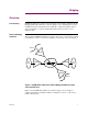
Bridging Overview Functionality PathBuilder S200 series switches support bridging of data traffic for Ethernet LANs. Bridging LAN traffic minimizes your networking costs by eliminating the need for redundant networks and maximizes the availability of dedicated facilities such as servers and printers, as well as public Frame Relay and X.25 services, across multiple LANs. Remote Bridging Solutions PathBuilder S200 series switches are intended for use in remote bridging solutions.
Mixed LAN Support PathBuilder S200 series switches support mixed LAN bridging, meaning you can configure an Ethernet interface in the same node. Refer to the “Mixed LAN Bridging” section on page 8 for more details. Translational Bridging PathBuilder S200 series switches can use the Translational Bridging feature to bridge traffic between Ethernet Networks. Translational Bridging provides a PathBuilder S200 series switch with the capability to bridge non-routable protocols.
In This Manual Topic See Page Bridging Features and Capabilities .............................................................. Token Ring LAN ...................................................................................... Ethernet LAN ........................................................................................... Mixed LAN Bridging ............................................................................... MAC Addressing ............................................................
In This Notice (continued) Topic See Page Bridge Statistics ............................................................................................ Spanning Tree Statistics ........................................................................... Detailed Bridge Link Statistics ................................................................ Bridge Link Filter Summary .................................................................... Transparent Bridge Forwarding Table Statistics ...............
Bridging Features and Capabilities Bridging Features and Capabilities Introduction This section describes bridging features and capabilities of PathBuilder S200 series switches. Bridging Primer As mentioned earlier, Bridging extends the size and coverage of a Local Area Network (LAN). PathBuilder S200 series switches provide bridging support for up to two 802.3 (Ethernet) LAN interfaces per node or one 802.5 (Token Ring) LAN interface) per node, and up to 32 remote bridge connections.
Bridging Features and Capabilities Ethernet LAN What Is It? Ethernet is a common implementation of LAN topology wherein stations are connected using a bus topology. Stations access the Ethernet using Carrier Sense with Multiple Access and Collision Detection (CSMA/CD). PathBuilder S200 Series Switch Support for Ethernet PathBuilder S200 series switch Ethernet functionality complies with the IEEE 802.
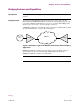
Bridging Features and Capabilities Example of Ethernet Bridge Operation Figure 5 shows an example of two Ethernet LANs connected across a WAN using two PathBuilder S200 series switches as bridges. The example shows a Frame Relay WAN application, but you can also bridge across an X.25 WAN. PB S200 Frame Relay PB S200 Figure 5. Ethernet Bridge Example For More Details... Bridging T0008-16F For more details on bridging Ethernet LAN traffic, see Transparent Bridging for Ethernet LANs on page 48.
Bridging Features and Capabilities Mixed LAN Bridging What is It? PathBuilder S24x, 26x, and 27x switches support a mixture of Token Ring and Ethernet interfaces configured in the same node. This means the PathBuilder S24x, 26x, and 27x switch is able to perform remote Transparent bridging for Ethernet LANs from the same PathBuilder S24x, 26x, and 27x switch as shown in Figure 6.
Bridging Features and Capabilities MAC Addressing What Is It? Bridges, whether they using Transparent Bridging, operate at the Data Link Layer, which is concerned with MAC addressing. The MAC Address is a 6-byte MAC (Media Access Control) address that identifies stations on a LAN. The IEEE administers distribution of the MAC address to ensure no duplicates occur in MAC addressing. This is accomplished by assigning a unique MAC address to each manufacturer.
Bridging Features and Capabilities LLC2 Local Termination LLC2 Local Termination PathBuilder S200 series switch support includes LLC2 Local Termination for your Bridging operations when passing SNA/SDLC data traffic. LLC2 Local Termination lets specific Token Ring ports generate and respond to LLC2 polls with local acknowledgments, thereby preserving bandwidth and preventing session timeouts.
Bridging Features and Capabilities Autolearn for Local Termination What Is It? Local Termination Autolearn reduces the amount of configuration you need to do by letting you spoof remote sessions without configuring a MAC address and a Service Access Point (SAP) for each station running a session to the host Front End Processor (FEP).
Bridging Features and Capabilities Filtering What Is It? Filtering lets you restrict data traffic from certain segments of your network. There are different methods used to filter data traffic on a bridged network.
Bridging Features and Capabilities Spanning Tree Protocol What Is It? Spanning Tree Protocol reduces multiple bridge paths between LANs to a single path. Instead of a mesh network with several paths to a destination, the Spanning Tree Protocol remaps the network so that only one path is active for traffic between any source station and any destination station. The other paths block any frames between the LANs. A spanning tree network eliminates parallel paths and traffic loops.
Bridging Features and Capabilities Dual Ethernet LANs What Is It? The PathBuilder S24x, 26x, and 27x switch supports up to two Ethernet LANs in t he same node. This means you can connect up to two Ethernet LANs to a single PathBuilder S24x, 26x, and 27x switch to perform bridging and routing of LAN traffic across the WAN to multiple Ethernet LANs. Before Dual Ethernet LAN, the PathBuilder S24x, 26x, and 27x switch supported only one Ethernet LAN port for remote bridging and routing of LAN traffic.
Basic Remote Bridging Examples Basic Remote Bridging Examples Introduction This section shows some common examples of bridging applications using PathBuilder S200 series switches. Remote Bridging Across a WAN Figure 9 shows a common Source Route Bridging operation for PathBuilder S200 series switches where two Token Ring LANs are attached across a WAN. For example, two LANs could be bridged using two PathBuilder S200 series switches interconnected by an X.25 or Frame Relay link.
Basic Remote Bridging Examples A Less Complex Extended Bridge Figure 11 shows a possible arrangement of SVCs (PVCs for Frame Relay) that produces the same bridge arrangement as shown in Figure 10. Node 1 Token Ring 1 Node 2 Bridge 1 Bridge 1 Bridge 2 Bridge 3 Token Ring 2 SVC Connectors Node 3 Token Ring 3 Bridge 2 Bridge 3 Figure 11.
Bridge Hardware Components in PathBuilder S200 Series Switches Bridge Hardware Components in PathBuilder S200 Series Switches Introduction This section describes bridge hardware configuration and connections for the PathBuilder S200 series switch. Bridge Configuration and Connections Figure 12 shows the physical connections of the modules that provide bridging functionality for PathBuilder S200 series switch.
Bridge Hardware Components in PathBuilder S200 Series Switches 18 Bridging
Setting Up WAN Operation for Bridging Setting Up WAN Operation for Bridging Introduction With the 3Com Bridging Protocol option, you can use PathBuilder S200 series switches to connect remote LANs across a Wide Area Network (WAN), as shown in Figure 13. Codex Proprietary Protocol ID LAN Connection Subaddress Node 1 LAN AAA Bridge 1 Half Bridge 2 Half Node 3 LAN DDD Node 2 Bridge 1 Half Bridge 3 Half WAN LAN CCC SVC Connectors Bridge 2 Half Bridge 3 Half Figure 13.
Setting Up WAN Operation for Bridging LAN Connection Subaddress The LAN Connection Subaddresses identifies all LAN Connections. Incoming calls with a network address consisting of the Node Address specified in the Node record and the LAN Connection Subaddress, specified in the LAN Connection Table, are verified and allowed to connect to the WAN Adapter in order to reach the LAN bridges.
Configuring the PathBuilder S200 Series Switch for Bridging Operation Configuring the PathBuilder S200 Series Switch for Bridging Operation Introduction This section shows you how to configure a PathBuilder S200 series switch for bridging operation.
Configuring the PathBuilder S200 Series Switch for Bridging Operation Bridge Parameters Bridge Port Record After you configure the Node record and the LAN Port record for the bridge node, Parameters configure the Bridge parameters. Figure 14 shows the parameters that make up the Bridge Parameters record.
Configuring the PathBuilder S200 Series Switch for Bridging Operation *STPE Control Range: AUTO, MAN Default: MAN Description: The Spanning Tree Protocol Entity (STPE) module in the PathBuilder S200 series switch provides automatic calculation of the spanning tree. Spanning tree allows for the proper support of single route broadcast frames that occur in LANs.
Configuring the PathBuilder S200 Series Switch for Bridging Operation Bad Hello Timeout (continued) Description: Represents the timeout value in minutes. The Bad Hello counter is reset when the timeout expires and can be used to control how frequently the Hello counter reaches its alarm threshold.
Configuring the PathBuilder S200 Series Switch for Bridging Operation Note If STPE Control parameter value is AUTO, this parameter appears. Bridged Protocols Bridging T0008-16F Range: None, IP, IPX Default: None Description: Specify the routable protocols that can be bridged across BROUT or BRID links. “None” specifies no routable protocols (IP, IPX) will be bridged. “IP” specifies that IP packets can be bridged. “IPX” specifies that IPX packets can be bridged.
Configuring the PathBuilder S200 Series Switch for Bridging Operation Bridge Link Parameters Introduction The bridge uses Bridge Links as connections to the LAN and WAN networks. The LAN Bridge Link connects the bridge directly to the local LAN, and its parameters control the characteristics of this connection. The WAN Bridge Link parameters let you establish and maintain SVC connections to a remote LAN bridge.
Configuring the PathBuilder S200 Series Switch for Bridging Operation Parameters These parameters make up the Bridge Link Record. Entry Number Range: 1, 5 to 36 Default: 1 Description: Specify the Bridge Link number that references this record. Two Ethernet LANs can be configured on the PathBuilder S24x, 26x, and 27x switch using 1 and 2. Links 1-4 are reserved for LAN port connections. There are 32 possible WAN Bridge Links, numbered 5 to 36.
Configuring the PathBuilder S200 Series Switch for Bridging Operation Hop Count Limit Range: 0 to 7 Default: 7 Description: Specifies the maximum number of bridges through which a broadcast frame may pass on the way to its destination. Largest Frame Size Range: 516, 1500, 2052, 4472 Default: 2052 Description: Specifies the maximum size of the INFO field that this Bridge Link can send and receive.
Configuring the PathBuilder S200 Series Switch for Bridging Operation Protocol Filter Action Range: NONE, PASS, BLOCK Default: NONE Description: Functions similarly to the MAC Address Filtering Action parameter. The filtering is applied to each link. Frames passing on a link can be either incoming or outgoing. • NONE: No Protocol filtering using the Protocol Filter Table is to be performed for this link.
Configuring the PathBuilder S200 Series Switch for Bridging Operation Link Mode Range: NORMAL,RFC1294, TRANS Default: NORMAL Description: Specify one of the following: • NORMAL - Bridge link connects to another Bridge using the Link Control Protocol to determine remote Ring Number. This option is not supported for PVC connections. Use another option for PVC connections. • RFC1294- Bridge link uses RFC1294 (or RFC1490) bridging to connect to another Bridge or Frame Relay Access Device.
Configuring the PathBuilder S200 Series Switch for Bridging Operation LAN Connection Table Introduction The LAN Connection Table provides information about the connections that cross over the WAN. LAN Connection Table Parameters Figure 16 shows the LAN Connection Table parameters.
Configuring the PathBuilder S200 Series Switch for Bridging Operation *LAN Forwarder Type Range: ROUT, BRID, BROUT Default: ROUT Description: Specify if the LAN Connection is to pass bridged, routed, and/or brouted traffic: • BRID: Bridged LAN traffic is transported across this connection. • ROUT: Routed LAN traffic is transported across this connection. • BROUT: Both bridged and routed LAN traffic are transported across this connection.
Configuring the PathBuilder S200 Series Switch for Bridging Operation Encapsulation Type Range: RFC 877, RFC 1294 Default: CODEX Description: Specify the type of encapsulation used over this LAN connection. Encapsulation types supported include: • CODEX: Codex Proprietary Encapsulation • RFC 877/1356: RFC 877/1356 X.
Configuring the PathBuilder S200 Series Switch for Bridging Operation Billing Records Range: OFF, ON Default: OFF Description: Enables or disables the creation (storing and printing) of billing records for the LAN connection: • ON: Billing records are generated. • OFF: Billing records are not generated. Traffic Priority 34 Range: LOW, MED, HIGH, EXP Default: HIGH Description: Specify the Traffic Priority level of this LAN Connection.
Configuring the PathBuilder S200 Series Switch for Bridging Operation Limiting Bridge Frame Sizes Overview Although there are valid reasons for using larger frame sizes on bridges, there are limiting factors that must be considered when selecting a maximum frame size. There are several reasons for limiting the maximum size of the frame, especially where bridging is done remotely across a WAN: • The larger the frame, the longer it takes to transmit the frame on a WAN link.
Configuring the PathBuilder S200 Series Switch for Bridging Operation Increasing the frame size also causes the reduction in frame overhead. If a 1000 byte data packet required a 50 byte header (frame + IP + TCP), then if 2000 bytes were placed in the frame with the same frame, the difference in overhead is 50/1000 = 5% versus 2.5%. As the size of the data increases, the overhead becomes even less. However, at these levels, the gain is marginal. Other factors may reduce this method of gain considerably.
Configuring the PathBuilder S200 Series Switch for Bridging Operation Configuring Translational Bridging Introduction This section explains how to configure your PathBuilder S24x, 26x, and 27x switch to implement the Translational Bridging feature. What is Translational Bridging Translational Bridging allows a PathBuilder S24x, 26x, and 27x switch to bridge traffic between Ethernet and Token Ring networks.
Configuring the PathBuilder S200 Series Switch for Bridging Operation Port 13 Station A Port 19 PB S200 Switch Bridge Link 1 Transparent Bridge Bridge Link 5 LCON 1 PVC Station B Bridge LCON Link 6 2 Source Bridge Bridge Link 2 Ethernet Token Ring Port 13 Port Type: ETH Bridge Link Number: 1 Port 19 Port Type: TR Ring Number: 1 Bridge Link Number: 2 Bridge Link 6 Bridge Type: SR Link Mode: TRANS Virtual Ring Number: 2 Bridge Link 5 Bridge Type: TB LAN Connection 1 LAN Forwarder Type: BRID Bridg
Configuring the PathBuilder S200 Series Switch for Bridging Operation Bridge Frame Handling Introduction This section summarizes how PathBuilder S200 series switches handle frames during Source Route Bridge operation.
Configuring the PathBuilder S200 Series Switch for Bridging Operation Configuring Source Route Bridging Operation Introduction You configure a node for Source Route Bridging during normal bridge configuration. Refer to “Configuring the PathBuilder S200 Series Switch for Bridging Operation” section on page 21 for more details. This section provides some guidelines you should consider when configuring a node for Source Route Bridge operation.
Configuring the PathBuilder S200 Series Switch for Bridging Operation • LAN Side: The LAN port connection consists of one link. To configure the bridge module requires that you configure the LAN Port; the LAN Bridge; and the LAN Bridge Link, which passes the LAN traffic from the LAN Port to the LAN Bridge (always numbered “1”). • WAN Side: The WAN Adapter (default subaddress 94) is used to make the transition from the LAN to the WAN.
Configuring the PathBuilder S200 Series Switch for Bridging Operation Connecting a Station to a Server in Source Route Bridging Introduction The following is an example of the process involved in establishing a connection between a station on one Token Ring LAN with a server on a remote Token Ring LAN for a Source Route Bridging operation.
Configuring the PathBuilder S200 Series Switch for Bridging Operation Frame PC PC ? LAN AAA ? PC ? PB S200 ? PC Figure 22. Server’s Destination MAC Address Not on LAN AAA 3) After receiving no response on the local LAN, the PC uses Source Route Bridging (SRB) to find the path to the remote server. The PC can resend the TEST frame indicating that the frame is to be bridged over all routes. The PC resends an All Route Explorer (ARE) TEST frame via its SRB software (Figure 23).
Configuring the PathBuilder S200 Series Switch for Bridging Operation 5) The PathBuilder S200 series switch transfers a copy of the ARE frame from the LAN Port across LAN Bridge Link number 1 to the Bridge (Figure 24). Since the frame is an All Routes Explorer, the Bridge broadcasts the frame across each of the existing WAN Bridge Links (32 max) to the WAN Adapter module.
Configuring the PathBuilder S200 Series Switch for Bridging Operation PB S200 5 WAN Adaptor Bridge LAN Port LAN xxx 1 6 7 PC Server WAN Bridge Link PB S200 PB S200 Bridge LAN AAA LAN Port 1 5 6 5 WAN Adaptor WAN Network WAN Adaptor 7 Bridge LAN Port LAN CCC 1 6 7 LAN Bridge Link PB S200 5 WAN Adaptor 6 Bridge LAN Port 1 LAN zzz 7 Figure 25.
Configuring the PathBuilder S200 Series Switch for Bridging Operation 8) The server issues a Specific Route TEST frame (also called a non-broadcast frame) in response using the route indicated in the ARE TEST frame. Note that the server does not have to broadcast (use ARE) to get the TEST response back to the PC; it uses a Specifically Routed TEST frame (Figure 26).
Configuring the PathBuilder S200 Series Switch for Bridging Operation Attaching a Station This table describes how a station attaches to a ring. to a Ring Step Action 1 The station requests values for the ring’s operational parameters from the RPS. 2 An attaching station also sends the RPS its adapter software level as well as its Upstream Neighbor Address. If... Bridging T0008-16F Result/Description Then...
Transparent Bridging for Ethernet LANs Transparent Bridging for Ethernet LANs Introduction A transparent bridge, also known as a spanning tree bridge, decides where to relay Ethernet LAN frames by using the spanning tree protocol to develop and maintain a loop-free topology. Using spanning tree, you can add a bridge anywhere in the Ethernet LAN without creating loops. The network devices are not involved in this decision process, which is transparent to them.
Transparent Bridging for Ethernet LANs Transparent Bridge Figure 27 shows how the Forwarder and the Hardware Accelerator process a frame. Forwarder Example A frame arrives at the TB Forwarder. Drop the frame. YES YES Is the MAC Source Address in the forwarding table? NO Do filters match? NO YES Is the inbound flag for a Unicast or Multicast frame set? NO Learn the Source Address.
Transparent Bridging for Ethernet LANs Figure 28 shows the relationship of the Forwarder and Hardware Accelerator to the Forwarder/ LAN and WAN Handlers. Hardware Accelerator and LAN/WAN Handlers LAN Handler 1 5 TB Forwarder 1 WAN Handler 36 32 HW Accelerator Figure 28.
Transparent Bridging for Ethernet LANs Forwarder Functions The Forwarder bridging logic includes decisions such as: • Which Link(s) the frame should be sent to. If the destination address of the frame exists in the Forwarding Table, and there is a link number associated with it, then the Forwarder checks whether filters should be applied to the frame and cause the frame to be dropped. If all these conditions are satisfied and no filters apply, the Frame is sent over to the link via the Handler.
Transparent Bridging for Ethernet LANs Forwarder and STPE The Forwarder cleans up all entries in the Forwarding Table when there are spanning tree topology changes taking place. These actions are considered services the Forwarder provides to the Spanning Tree Protocol Entity (STPE). The Forwarder provides these services through MACRO routines so that they are accessible to the entire system. Note The Forwarder is not required to pass STPE traffic to the handlers.
Transparent Bridging for Ethernet LANs Forwarder Database and Spanning Tree How They Work Together There is a close relationship between the forwarding database and the spanning tree. The spanning tree can be manually configured. This is a reasonable thing to do in the case where a stable environment exists since it saves CPU processing by eliminating aging timers and the broadcasting that is employed when the forwarding table does not have a suitable entry.
Transparent Bridging for Ethernet LANs Using Filters Support The Forwarder provides its own filtering facility which is used to reduce unnecessary traffic and to provide security.
Transparent Bridging for Ethernet LANs Multicast Link Protect Flag When a multicast/broadcast frame comes from a link with the Multicast Protect Flag set, and if its source address is not found in the Permanent Station Address list, the frame is dropped. When a multicast/broadcast frame is sent out over a link with the Multicast Protect Flag set, and if its destination address is not found in the Permanent Station Address List, the frame is dropped.
Transparent Bridging for Ethernet LANs Transparent Bridge Configuration Parameters TB Forwarding Table Figure 29 shows the Transparent Bridge Forwarding Table parameters. Node: Address Menu: Configure Bridge Date: Time: Path: Bridge Parameters Bridge Link Parameters MAC Address Filter Table Protocol Filter Table NETBIOS Name LSS Parameters TB Forwarding Table Entry Number *Local MAC Address *Bridge Link Number Figure 29.
Bridge Filtering Bridge Filtering What is It? Bridge filtering prevents extraneous traffic from traversing the WAN and stops the unintentional proliferation of traffic onto other remote LAN segments. In Ethernet Transparent Bridging, the broadcast feature lets stations determine routes to other end stations. Broadcasting to the entire network can unnecessarily degrade performance because of broadcasts traversing LAN segments that are not in any part of the network where the target station resides.
Bridge Filtering MAC Address Filtering What Is It? This feature lets you filter bridge traffic based on MAC address. The Bridge Link Table and the MAC Address Filter Table are used to configure MAC Address filtering. The Bridge Link Table specifies: • Whether or not any filtering action is to be performed. • The filtering action to perform when the MAC frame address is not found in the MAC Address Filter Table.
Bridge Filtering Parameter MAC Address Filtering Action Parameter Selections Outgoing Destination Address Link Action Perform filtering action on an outbound frame for the indicated MAC Destination address. List of Links Specifies the links associated with the preceding link action parameters in this table. When Passlist (PL) is specified, the associated listed links pass the frame and the unlisted links block it.
Bridge Filtering MAC Filtering Process Figure 30 shows the MAC Filtering process. Check Bridge Link Record or Entry NONE MAC Address Filtering Action Setting? Pass frame without filtering PASS or BLOCK Check MAC Address Filter Table for match of frame MAC Address YES Apply Table Filter: PASS or BLOCK Frame MAC Address in MAC Address Filter Table? NO Check Bridge Link Table MAC Address Filtering Action Setting? PASS BLOCK Block the frame Pass the frame Figure 30.
Bridge Filtering Mac Filtering Process As shown in Figure 30, if a match is detected, the system applies the filtering action configured for that entry. The filtering action is to either PASS the frame or BLOCK the frame for all links or for a configured list of links. This filtering action overrides the action specified in the MAC Address Filter Action parameter.
Bridge Filtering MAC Address Filtering Examples Introduction This section shows two filtering examples. Figure 32 shows how the source address can be used to filter frames. Figure 35 shows how the MAC Address Filter Table can be used to filter frames by combining multiple source and destination addresses. First Example In Figure 32, the source address (MAC Address represented by A) is used to filter frames passing in or out of the bridge via links 1, 5, and 6 (Figure 32).
Bridge Filtering Configuring the MAC Address Filter Table Parameter Values Entry Number 1 MAC Address A Incoming Source Address Action Passlist List of Links 1 Outgoing Source Address Action Passlist List of Links 5 In a Bridge Link Record, Pass (or Block) tells the system to check the MAC Address Filter Table to find out what filtering to perform. If the Bridge Link Record specified None, then the frame would pass without any filtering.
Bridge Filtering Identifying Address Links for MAC Addressing Why it is Important Identifying the address links is an important step in configuring MAC Address filtering. A Source Address link allows a device on the LAN to send frames. A Destination Address link allows a device on the LAN to receive frames. The Incoming Source Address link provides a path for a frame to go from the Token Ring to the bridge. The Outgoing Source Address link provides a path for a frame to go from the bridge to the WAN.
Bridge Filtering MAC Wildcard Filtering What Is It? MAC wildcard filtering is an enhancement to the Motorola Network Access Products MAC Filter table. MAC wildcard filtering lets you configure the MAC filter tables and use wildcards “*” to designate numeric pieces of the MAC address. The MAC Address filter lets you configure a table of MAC Address filters (each filter contains a MAC address which is a string of 12 characters from the range 0-9, A-F).
Bridge Filtering Configuring the MAC Address Filter Table Introduction The MAC Address Filter Table controls which frames are allowed to pass on to different links and lets you control proprietary information that you may not want to go to another LAN. It is also useful in controlling the unnecessary proliferation of broadcast frames in the LAN network. MAC Address Filter Figure 35 shows the MAC Address Filter Table parameters.
Bridge Filtering Parameters These parameters make up the MAC Address Filter Table. Entry Number Range: 1 to 300 Default: 1 Description: Entry number used to reference this table record for filtering action. Note If you do not wish to determine filter action for this link through the MAC Address Filter Table, select NONE in the Bridge Link record.
Bridge Filtering Outgoing Source Address Link Action Range: PASS, BLOCK, PASSLIST, BLOCKLIST Default: PASS Description: Outgoing source means that the frame is leaving the bridge for the WAN. Therefore, a given source address frame will be outgoing from bridge to WAN and incoming from LAN to bridge (provided it does not get blocked due to filtering). • PASS: Pass outgoing frames with this MAC Address value on all links that are referencing this table. If this value is chosen, skip the List of Links.
Bridge Filtering Outgoing Destination Address Link Action Range: PASS, BLOCK, PASSLIST, BLOCKLIST Default: PASS Description: The Outgoing Destination Address link provides a path for a frame to go from the bridge to the LAN. It allows a device on a Token Ring to receive frames. • PASS: Pass outgoing frames with this MAC Address value on all links that are referencing this table.
Bridge Filtering Protocol Filtering What is It? Protocol filtering is used to prevent nodes operating with a certain protocol from operating outside their intended scope. For protocol filtering, the same fundamentals apply as with MAC Address Filtering except the Bridge Link record specifies Protocol Filtering Action. This table shows how to configure the Bridge Link record for protocol filtering.
Bridge Filtering Configuring the Protocol Filter Table Introduction The Protocol Filter Table prevents stations operating with a certain protocol from operating outside their intended scope. This filtering action is applied to that part of the frame that defines the protocol carried by the frame. Note A Table boot must be performed to implement changes to the Protocol Filter Table parameters. Protocol Filter Table Parameters Figure 36 shows the Protocol Filter Table parameters.
Bridge Filtering Protocol Type Range: DSAP, SNAP Default: DSAP Description: Indicates what type of protocol is involved in the frame. DSAP (Destination Service Access Point): The protocol value to be filtered is the Destination SAP field of the 802.2 LLC formatted frame. This type includes: Protocol SAP (hex value) Banyan BC (used only for 802.5) Novell IPX E0 (used only for 802.
Bridge Filtering Incoming Protocol Link Action Range: PASS, BLOCK, PASSLIST, BLOCKLIST Default: PASS Description: Specifies the action to be taken on the incoming protocol. These actions include: PASS, BLOCK, PASSLIST, or BLOCKLIST. • PASS: If this value is used, incoming frames with the specified protocol value are passed on all links. All other protocols are blocked on incoming links. If this value is chosen, skip the List of Links parameter.
Bridge Filtering DSAP Values The DSAP is a 1-byte ID found in the LLC field (see Figure 37). You set this value in the Protocol Value parameter of the Protocol Filter Table. Examples of DSAPs include: • • • • IBM (04, 08,...) Banyan Vines (BC) Novell IPX (E0) IBM NetBIOS (F0) LLC Field DSAP SSAP Control LLC Info Figure 37. Protocol ID DSAP Located in LLC Field SNAP Protocol ID The SNAP is five bytes and is also found in the LLC field.
Bridge Filtering Example of Protocol Filter Table This table provides an overview of the Protocol Filter Table parameters. Parameter Entry Number Protocol Type Protocol Value Incoming Protocol Link Action Outgoing Protocol Link Action List of Links Bridging T0008-16F Action(s) Used to reference this table record. Indicates what type of protocol is involved in the frame. Selections include: NONE, DSAP, and SNAP. Indicates the value of the protocol that is filtered or forwarded.
Bridge Filtering NetBIOS Name Filtering Introduction The NetBIOS Name Filtering feature compares NetBIOS broadcasts to a “pattern” that may have a wild card “*” character at the end. For example, if all servers have a naming convention with the first part of the name the same, for example, “SVR...”, then you can complete only one entry in the NetBIOS Filter Table to permit broadcasts to and from the “SVR*” name pattern.
Bridge Filtering Forcing a Local Domain With NetBIOS Name Filters The NetBIOS Name Filtering feature can also force a local domain, or context, of a NetBIOS name. All branch offices, for example, may connect to an SNA gateway function in OS/2 by accessing a gateway local to the branch. Under normal bridging conditions, you configure the SNA gateway NetBIOS server with a different name for each branch office and every workstation to attach to the name for its branch office.
Bridge Filtering Configuring NetBIOS Name Filtering Introduction This section describes how to use the Control Terminal Port (CTP) to configure NetBIOS Name Filtering. How to Configure NetBIOS Name Filtering Follow these steps: Step Action 1 Configure the NetBIOS Name Filter Action parameter in the Bridge Link Parameters. 2 Configure the parameters in the NetBIOS Name Filter Table record.
Bridge Filtering Configuring NetBIOS Name Filtering To access the NetBIOS Name Filter Action parameter, follow the steps below: Step Parameter Action 1 Select Configure -> Configure Bridge -> Bridge Link Parameters from the CTP Main menu. 2 Enter the number of the link that you are defining and complete the NetBIOS Name Filter Action parameter using the description in the Parameters section that follows. Result Entry Number 1 appears.
Bridge Filtering Configure NetBIOS Figure 41 highlights the NetBIOS Name Filter Table selection in the Configure Name Filter Table Bridge menu. Node: Address: Menu: Configure Bridge Date: Time: Path: (Main.5.22) Bridge Parameters Bridge Link Parameters MAC Address Filter Table Protocol Filter Table NetBIOS Name Filter Table LSS Parameters LLC LT Station Table LLC LT WAN Parameters LLC LT Profile Table #Enter Selection: Figure 41.
Bridge Filtering Typical Filtering For the typical case, where you filter client broadcast traffic by default and pass server traffic as discussed in the ““Typical Filtering” section on page 81.” • Define only the NetBIOS Name field. • Define one record for each wildcard pattern that encompasses all NetBIOS service names.
Bridge Filtering Incoming NetBIOS Name Link Action Range: PASS, BLOCK, PASSLIST, BLOCKLIST Default: PASS Description: The following describes the options that you can define for the link: • PASS — Passes all incoming frames with a specified NetBIOS name on all links. • BLOCK — Blocks all incoming frames with a specified NetBIOS name on all links. Passes incoming frames with other NetBIOS names on all links.
Bridge Filtering Outgoing NetBIOS Name Link Action Range: PASS, BLOCK, PASSLIST, BLOCKLIST Default: PASS Description: These are the options that you can define for the link • PASS — Passes outgoing frames with the specified NetBIOS name on all links. All outgoing frames with other NetBIOS names are blocked on all links. • BLOCK — Blocks outgoing frames with the specified NetBIOS name on all links. All outgoing frames with other NetBIOS names are passed on all links.
Bridge Filtering NetBIOS Name Filtering Statistics Introduction For each bridge link, you can display the number of packets discarded due to matching a NetBIOS name filter on a bridge filter statistics screen. There are separate counts for the number discarded on incoming and outgoing directions for each bridge link. Check Detailed Bridge Link Stats Figure 42 shows the detailed statistics screen that includes counts of the number of NetBIOS broadcasts filtered on the link.
Bridge Filtering NetBIOS Packet Formats Introduction NetBIOS Name Filtering operates only on the Microsoft or IBM-compatible NetBIOS implementations, which represents the majority of NetBIOS implementations. It does not recognize at this time Novell’s implementation of NetBIOS over IPX, nor does it recognize the packet format of NetBIOS over TCP (RFC 1000). NetBIOS Name Filtering operates on Ethernet LANs.
Spanning Tree Protocol Entity (STPE) Spanning Tree Protocol Entity (STPE) Introduction The Spanning Tree Protocol Entity (STPE) is part of the PathBuilder S200 series switch Source Route Bridge functionality. The parameters that control Spanning Tree Protocol operation are in the Bridge Record and Bridge Link Record. In the Bridge Record, the STPE Control parameter setting determines whether Automatic or Manual Spanning Tree is used.
Spanning Tree Protocol Entity (STPE) Bridge Links There are three types of bridge links within a given spanning tree network: • The Root Bridge Link. The link representing the best path to the root bridge. A root link is always on the spanning tree. • The Designated Bridge Links. All the other bridge links on the spanning tree. • The Standby Bridge Links. All other bridge links which are not on the spanning tree.
Spanning Tree Protocol Entity (STPE) Tips on Spanning Tree Determining a spanning tree in order to set up a manual tree may seem more labor intensive than letting the bridge network determine the tree by algorithm. However, even with automatic spanning tree determination, you must study the possible arrangements of resulting trees and assign the bridge priorities accordingly to avoid unreasonable performance due to long data paths.
Spanning Tree Protocol Entity (STPE) STPE Parameter Setting Considerations Introduction This section discusses how the bridge and bridge link parameters can be used to influence the design of a bridge network and to show how they relate to overall PathBuilder S200 series switch configuration during spanning tree operation.
Spanning Tree Protocol Entity (STPE) Setting the Root Bridge of the Spanning Tree The bridge with the lowest Bridge ID becomes the root bridge in a spanning tree network. The Bridge ID is made up of two parts: the Bridge Priority and the MAC address of the LAN port. You modify these elements during bridge configuration from the Bridge Priority parameter in the Bridge Parameters record and the MAC Address parameter in the LAN Port record. All bridges have the same default priority value (32768).
Spanning Tree Protocol Entity (STPE) Determining Path Costs Bridges use Path Cost to determine their Root Link. The range of Path Cost is 0 to 65535. The lower the path cost, the more likely this path will be used. Use This table to determine the path costs for each type of link in your network. Type of Network Speed STPE Path Cost 802.3 10 Mbps 10 802.5 4 Mbps 25 802.5 16 Mbps 6 serial 1.54 Mbps 65 serial 384 kbps 260 serial 56 kbps 1768 serial 19.
Spanning Tree Protocol Entity (STPE) Consider the Nature and Expected Number of SVCs A further consideration for setting path cost is the nature and expected number of SVCs that the bridge link uses to achieve its connectivity and adjust the value of incremental path cost accordingly. For example, consider the topology shown in Figure 45. Node B Node A Bridge 1 X25-1 X25-3 X25-2 MX25 Bridge 2 Node C Bridge 3 Node D Bridge 4 Node E Figure 45.
Spanning Tree Protocol Entity (STPE) There are two final considerations when selecting links on the basis of reported cost, Other Considerations for when the costs and indicated root bridge on different links are the same. The first is the case where, for example, B4 receives a message on link 8 from B3 designating Selecting Links B1 as the root bridge with a cost of 10608 to the root. At the same time, B4 receives a message on link 8 from B2 designating B1 as the root bridge with a cost of 7072.
Spanning Tree Protocol Entity (STPE) The same priority mechanisms that determine the root link are also applied in determining which links become designated links (a root link is never a designated link). The designated link is the link that is responsible for issuing the bridge messages when more than one link is involved in a network.
Spanning Tree Protocol Entity (STPE) Spanning Tree Timers Introduction If the spanning tree converges to a final topology (it usually does, but misconfiguration as discussed below can cause instability and lack of convergence), the topology is maintained by timed messages initiated by the root bridge and sent out its designated links. Subsequently, bridges receive the message on their root link and in turn pass the message along the spanning tree by transmitting it on their designated links.
Spanning Tree Protocol Entity (STPE) Other Considerations One important consideration is based on the fact that any bridge downstream from the root bridge copies the message received on the root link (which is also passed along designated links), and the retained copy is constantly aged. If the age of the message reaches the value of Max Age, the bridge discards the stored message and chooses another link as the root link.
Spanning Tree Protocol Entity (STPE) Bridge Forward Delay Timer Forward Delay For transparent bridges the bridge Forward Delay is used to allow the spanning tree algorithm to converge to a stable topology before the bridging process is allowed to proceed. Spanning tree topology determination is an iterative process and requires time to converge.
Spanning Tree Protocol Entity (STPE) Suppose all bridges come up at the same time. Initially, at t=0, all bridges think they are the root and they issue the messages shown on the t=0 line. For simplicity, the bridge ID is a two digit number and the couplet such as 01,3561 should be interpreted as: root_ID, cost_to_root. The messages sent to the LAN attached to B1 and B4 are irrelevant to this discussion and are not shown.
Spanning Tree Protocol Entity (STPE) Aging Timer The Aging Timer is a configurable parameter found in the Bridge Parameters Record. It allows learned station addresses to be aged in the station address cache and deleted once their age has reached the value of the Aging Timer parameter. This allows automatic updates for certain dynamic conditions, such as when a station is physically moved from one part of the network to another.
LLC2 Local Termination LLC2 Local Termination LLC2 Local Termination LLC2 Local Termination lets specific Token Ring ports generate and respond to LLC2 polls with local acknowledgments, thereby preserving bandwidth and preventing session timeouts in a Bridging application. Local Termination, also referred to as “spoofing,” provides an efficient means for carrying out an LLC2 session between two SNA end stations attached to separate Token Ring LANs connected by a Wide Area Network (WAN).
LLC2 Local Termination Before Local Termination Without Local Termination, networks face significant problems with bandwidth usage and session timeouts due to polling overhead between the host and terminal, as well as network delays. For example, Figure 49 shows a terminal session on a source route bridged Token Ring LAN connected to a host without Local Termination.
LLC2 Local Termination Supported Topologies Local Termination is supported only on Token Ring topologies configured for Source Route Bridging. And there are two important guidelines to remember when you are planning your Local Termination strategy: • When you turn on Local Termination in your network, the MAC address/SAP value you assign is always locally terminated.
LLC2 Local Termination Proper LT configuration Figure 52 shows a Token Ring LAN properly configured for Local Termination. LLC2 Keepalives/Acks SNA FEP 1 2 CC LLC2 Keepalives/Acks 3 LLC2 Keepalives/Acks CC Figure 52. Example of Proper LT Configuration Local Termination running on PathBuilder S200 series switch bridges 1, 2, and 3 at the edge points of the network provide a simple solution to congestion and bandwidth problems across the entire network.
LLC2 Local Termination Spoofing Local termination or “spoofing” of LLC protocol means that acknowledgments to information frames and certain supervisory frames are handled locally by the spoofer. The spoofer, the LT software in a PathBuilder S200 series switch, ensures the acknowledged information frames are reliably delivered to the destination peer spoofer and that any flow control issues are handled appropriately.
LLC2 Local Termination Traffic Priority & Local Termination You can significantly optimize your spoofing operations by prioritizing Local Termination traffic and regular bridge traffic. By assigning a separate lower priority to spoofer traffic, the regular bridge traffic is queued quicker. The extra delay of spoofer traffic does not affect the acknowledgments of frames on the LAN.
LLC2 Local Termination Configuring Local Termination Configuring for Local Termination Perform the following procedures to configure Local Termination on a Bridge node. Step Before You Begin Action 1 Configure the node. 2 Configure the ports. 3 Configure the route selection table. 4 Configure the LAN connection table. 5 Configure the Mnemonic Table and PVC Setup table. 6 Configure the bridge for Local Termination.
LLC2 Local Termination Step Action (continued) 2 Configure all of these LT configuration options. Choose one to begin. • LLC LT Station Table Then: Go to “Configuring the LT Station Table” for details. Result LLC LT Station Table Configuration appears. LLC LT WAN Configuration • LLC LT WAN Parameters appears. Then: Go to the section “Configuring the LT WAN Parameters." • LLC LT Profile Table Then: Go to the section “LLC LT Profile Table Configuration.” LLC LT Profile Table Configuration appears.
LLC2 Local Termination Local SAP Range: 01 to FE (hexadecimal) Default: 04 Description: This SAP must match the source SAP of the frame received from the LAN port for the session to be spoofed. If you are using Local Termination Autolearn, specify the remote Host SAP for the local MAC.
LLC2 Local Termination T2 Rx Ack Timer (continued) Boot Type: LLC LT WAN Parameters. Ti Inactivity Timer Range: 2 to 255 (seconds) Default: 30 Description: The Idle Timer is used by a station to detect an inoperative condition of the logical link. This timer is started when the link becomes idle (no data to pass and no outstanding acknowledgments) and if it expires, the station sends a supervisory frame with the pole bits set to 1. Boot Type: LLC LT WAN Parameters.
LLC2 Local Termination Tx Window Size Range: 1 to 15 Default: 7 Description: Transmit window size is the maximum number of I frames a station may transmit without acknowledgment. Boot Type: Node Boot LCC LT WAN Data Priority LLC LT Profile Table Configuration Range: HIGH, MEDIUM, LOW Default: HIGH Description: Specifies the transmission priority of the LLC LT data. Boot Type: LLC LT WAN Parameters. These parameters make up the LLC LT Profile Table.
LLC2 Local Termination T1 Reply Timer Range: 1 to 25 (seconds) Default: 1 Description: This Ack timer is used by a station to detect a failure of the remote station to acknowledge an outstanding I frame or supervisory frame with the pole bit set to 1. Boot Type: Tables and Node Record. T2 Rx ACK Timer Range: 1 to 255 (tenths of seconds) Default: 1 Description: Specifies how long the station withholds acknowledgment of a frame from the remote station that requires acknowledgment.
LLC2 Local Termination N3 ACK Delay Count Range: 1 to 15 Default: 3 Description: The Receive Count is used with T2 to reduce the number of acknowledgments a station generates. The receive count is used by a station to determine how many frames it receives from the remote station while withholding acknowledgment of these frames. This reduces the number of acknowledgments generated by a link station.
LLC2 Local Termination Deleting LT Configuration Records Overview You can delete the following LLC2 LT configuration records if you no longer use them: • LT Station Table • LT Profile Table Before You Begin Choose List Bridge from the CTP Main menu to obtain a list of the configured LT session records. Procedure This procedure describes how to delete LT session configuration records. Step Bridging T0008-16F Action Result 1 Select Delete Record, from the The Delete Record menu appears.
Mixed LAN Operation Mixed LAN Operation Overview PathBuilder S24x, 26x, and 27x switches support a mixture of Token Ring and Ethernet interfaces configured on the same node. This means the PathBuilder S24x, 26x, and 27x switch is able to perform remote Transparent bridging for Ethernet LANs and remote Source Route Bridging from the same PathBuilder S24x, 26x, and 27x switch, as shown in Figure 54. Ethernet 1 Port 13 PB S200 Port 19 Ethernet 2 Ethernet 1 WAN PB S200 Ethernet 2 Figure 54.
Mixed LAN Operation Steps to Configure To perform mixed LAN bridging operation in a PathBuilder S24x, 26x, and 27x switch, configure a unique bridge link and router interface number for each LAN Mixed LAN Bridging Operation interface from the Port record. You must also configure the WAN bridge link to support Transparent Bridging and Source Route Bridging. Follow these steps to configure Mixed LAN Bridging, as shown in Figure 54.
Mixed LAN Operation Step Action (continued) Result/Description 9 Type ; and press Return. The record is saved. 10 Perform a Bridge Link boot from the Boot menu. This enables the bridge link. 11 Configure the WAN bridge link to This enables TB and SR on the support Transparent Bridging and WAN link. Source Route Bridging. Select Bridge Link Parameters and type in a WAN entry number from 5 to 36 to display the Bridge_Type parameter. Enter the string BOTH_SR_AND_TB. 12 Type ; and press Return.
Dual LAN Ethernet Dual LAN Ethernet What Is It? The Dual LAN Ethernet feature lets your PathBuilder S24x, 26x, and 27x switch support up to two Ethernet LAN interfaces to perform bridging and routing of LAN traffic across multiple LANs. Before Multiple Ethernet LAN, the PathBuilder S24x, 26x, and 27x switch supported only one Ethernet LAN port for remote bridging and routing of LAN traffic.
Dual LAN Ethernet Routing In IP/IPX or AppleTalk routing environments, do not connect both Ethernet LAN ports to the same Ethernet segment with identical routing decision values. This is not supported. How to Configure Dual Ethernet LAN Follow these steps to configure a node for Multiple Ethernet LAN. 118 Step Action Result/Description 1 Make a local CTP connection to a PathBuilder S24x, 26x, and 27x switch. The CTP is physically connected to the device you are configuring.
Dual LAN Ethernet Step 10 For Details on Parameters... Bridging T0008-16F Action (continued) Perform a Bridge Link boot from the Boot menu. Result/Description This enables the bridge link. See the PathBuilder S200 Series Basic Protocols for details on Ethernet LAN port parameters for Multiple LAN Ethernet operation. 119 Release 5.
LAN Server Subsystem LAN Server Subsystem What is It? The LAN Server Subsystem (LSS) software lets PathBuilder S200 series switches such as the PathBuilder S200 series switch communicate with an IBM LAN Manager to provide the following support for Token Ring Source Route Bridging applications: • • • • Ring Error Monitor (REM) Configuration Report Server (CRS) Ring Parameter Server (RPS) LAN Bridge Server What You Need to Configure The LAN Server Subsystem (LSS) Record is configured for the Token Ring/S
LAN Server Subsystem Statistics and Alarms Bridging T0008-16F Statistics and status alarm thresholds maintained by the LSS are specific for the IBM LNM and can be accessed by the IBM LNM, but not from the CTP. 121 Release 5.
LAN Server Subsystem Configuring the LSS Record Example of LCC Record Figure 56 shows the LSS Record parameters used to configure a PathBuilder S200 series switch for LSS operation. Node: Address: Menu: Configure Bridge Date: Time: Path: Bridge Parameters Bridge Link Parameters MAC Address Filter Table Protocol Filter Table LSS Parameters *Virtual Port’s MAC Address *Virtual Bridge ID *Path Trace Control *Functional Address Mask Figure 56.
LAN Server Subsystem *Virtual Bridge ID Range: 0 to 15 Default: 0 Description: Represents the bridge ID of a virtual source routing bridge that connects the local TR LAN to the virtual TR LAN. *Path Trace Control Range: ENABLE, DISABLE Default: DISABLE Description: Specifies whether or not the LBS is enabled to send the Path Trace notification frames to the IBM LAN Network Manager.
Bridge Statistics Bridge Statistics Introduction The Bridge Statistics section provides information about the LAN Port, Bridge Links, LAN Connection, and the Spanning Tree. Figure 57 shows the Bridge Statistics Menu screen.
Bridge Statistics Spanning Tree Statistics Spanning Tree (STPE) Status Figure 58 shows the information displayed by the Spanning Tree Status report.
Bridge Statistics Term (continued) 126 Description State The STPE view of the link’s current state. The possible states are: • Disabled: The STPE is disabled. (If STPE Control parameter is MAN) • Blocking: The STE frames are blocked on this bridge link. • Listening: The STE frames are blocked. Listening to STPE PDUs. • Learning: The STE frames are blocked. Learning the topology from STPE PDUs. • Forwarding: The STE frames can be forwarded on this bridge link.
Bridge Statistics Detailed Bridge Link Statistics Introduction Figure 59 and Figure 60 show sample statistics screens.
Bridge Statistics Description of Screen Terms This table describes Detailed Bridge Link Statistics terms. Term Description Bridge Link Status Following are the possible states: • Not Configured: This record is not configured. • No LAN Port: No physical LAN Port. • Active: Link is operational. • Congestion: Link is operational but congested. • Disabled: Disabled by Bridge Link disable command. • SW Disables: Disabled by the operating software because of internal error.
Bridge Statistics Term (continued) Description SR (Source Route): Received/Transmitted: The number of Source Route frames Frame Summary received/sent by the bridge. • SRF: Specifically Routed Frames. • ARE: All Route Explorer. Also called all route broadcast. • STE: Spanning Tree Explorer. Also called Single Route Explorer (SRE) or single route broadcast. • Frame Totals: The total number of frames received and transmitted by the bridge.
Bridge Statistics Bridge Link Filter Summary Example of Bridge Link Filter Summary Figure 61 shows the information displayed by the Bridge Link Filter Summary. The filters from MAC Address Filter Tables and Protocol Filter Tables are sorted for a bridge link and displayed.
Bridge Statistics Term (continued) Description Active Filters: MAC Address • MAC Address: 6-byte value of MAC Address parameter from the MAC Filter Table. • Source In: Value (PASS or BLOCK) from the MAC Filter Table. Action to be taken on an inbound frame having the indicated MAC Source address. • Source Out: Value (PASS or BLOCK) from the MAC Filter Table. Action to be taken on an outbound frame having the indicated MAC Source address. • Destination In: Value (PASS or BLOCK) from the MAC Filter Table.
Bridge Statistics Transparent Bridge Forwarding Table Statistics TB Forwarding Stats Example TB Forwarding Table statistics are shown in Figure 62. Node: Address: TB Forwarding Table Stats Date: Learned Entry Discards: 0 Available Entries: 7997 Aging Timer: 3600 Forwarding Database: MAC Address 03-00-FF-FF-FF-FF 08-00-3E-00-1B-96 FF-FF-FF-FF-FF-FF Time: Page: 1 of 1 Learned Entries: 0 Maximum Entries: 3 Bridge Link Number Status Other Other Other Press any key to continue (ESC to exit)...
Bridge Statistics Term (continued) Forwarding Database Bridging T0008-16F Description • MAC Address: 6-byte value of MAC Address parameter from the MAC Filter Table. Indicates a MAC Address for the list of entries in the forwarding database displayed by the status/statistics screen. • Bridge Link Number: Indicates the corresponding bridge link number used to forward a frame with the given MAC Address. • Status: Indicates how the forwarding entry was learned.
Bridge Statistics Transparent Bridge Detailed Bridge Link Statistics Detailed Bridge Link Statistics Figure 63 shows page 2 of the Detailed Bridge Statistics screen. This page reflects Transparent Bridging statistics when TB is configured on the node.
Bridge Statistics Term TB Frame Summary TB Frames Discarded TB Filter Discards Bridging T0008-16F Description (continued) Frames Received/Transmitted: • Unicast: This is a count of frames received/transmitted with an individual (non-group) MAC level address • Multicast: This is a count of the number of frames received/ transmitted with a group MAC level address • Broadcast: This is a count of the number of frames received/ transmitted with the broadcast MAC level address (FF-FF-FF-FF-FF-FF) • Frame To
Bridge Statistics LAN Connection Statistics Example of LAN Connection Statistics Menu The LAN Connection Statistics Menu screen is shown in Figure 64. Select the appropriate number to view a particular screen. Node: Address: Menu:Lan Connection Statistics Date: Time: Path:(Main.5.9) LAN Connection Stats LAN Connection Summary Stats Reset LAN Connection Stats Figure 64.
Bridge Statistics Node: Address: Date: Detailed LAN Connection Statistics: LCON-5 Time: Page: 2 of 2 Call Summary Connection Type: SVC Connection State: Improper Config Forwarders Connected: Remote Address: Number of auto-call attempts 0 Last clear cause code: 0 (Cleared by other end) Last clear diagnostic code: 0 (No more information) Packet Summary: Transmit Receive Data Call Request Call Accept Clear Request Clear Confirm Reset Request Reset Confirm 0 0 0 0 0 0 0 0 0 0 0 0 0 0 Press any key to c
Bridge Statistics Description of Screen Terms This table describes screen terms for pages 1 and 2 of the Detailed LAN Connection Statistics shown in Figures 65 and 66. Term Call Summary 138 Description This field provides information about the following: • Connection Type: Specifies whether the connection is an SVC or a PVC. • Connection State: Specifies the current state of the PVC or SVC.
Bridge Statistics Term (continued) Packet Summary Description • Data: Summary of each packet sent on the WAN and received from the WAN bridge link. • Call Request: Specifies the total number of Call Request Packets sent on the WAN and received from the WAN. • Call Accept: Specifies the total number of Call Accept Packets sent on the WAN and received from the WAN. • Clear Request: Specifies the total number of Clear Request Packets sent on the WAN.
Bridge Statistics Figure 67 shows the LAN Connection Summary Statistics. Example of LAN Connection Summary Statistics Node: Address: LAN Connection Summary Status LAN Connection ================== 1 Waiting Bridge Link ================ 5 Configured Date: Conn. Type ========== SVC Time: Page: 1 of 1 Remote Destination ===================== Press any key to continue ( ESC to exit ) Figure 67.
Bridge Statistics LLC2 LT Session Summary Statistics Sample of Session Figure 68 shows a sample of the LLC2 LT Session Summary Statistics report.
Bridge Statistics Heading (continued) Status 142 Description Indicates the session between the local and remote MAC addresses. • UP - MAC addresses are communicating using Local Termination. • DOWN - MAC addresses are not communicating. Session is the process of coming up or going down.
Bridge Statistics LLC2 LT Detailed Session Statistics Sample of Detailed Session Statistics Figures 69 and 70 show samples of the LLC2 LT Detailed Session Statistics report.
Bridge Statistics Description of Screen Attributes This table describes the screen attributes for the Detailed Session Statistics screens as shown in Figures 69 and 70. Heading Description Session Number: Refers to the entry number assigned between MAC addresses. Maximum number of sessions is 64. Station Number: Entry Number on LLC LT Station Table of local MAC/SAP. LLC Profile Name: Profile name table that this station uses which references the T1, T2, Ti, N2, N3, TW values.
Bridge Statistics Heading Description (continued) Local Station Session Summary Bridging T0008-16F TX Window: Transmit window size obtained from the configuration for the local station. Protocol State: Number of the state for current session with local device. Characters In: Number of user data characters received by the spoofer from the locally attached LAN station. Characters Out: Number of user data characters transmitted by the spoofer to the locally attached LAN station.
Bridge Statistics Heading Description (continued) Remote Spoofer Session Summary 146 TX Window: Transmit window size obtained from the configuration for LLC WAN parameters. Protocol State: Number of the state for current session with remote spoofer. Info: Number of information frames received or transmitted by the local spoofer to or from the remote spoofer. RR: Number of RR frames received or transmitted by the local spoofer to or from the remote spoofer.
Bridge Statistics Reset Statistics How to... Reset Port Statistics: Consistent with PathBuilder S200 series switch, the reset port statistics prompts you to enter the number of the port to be reset. For TR port Number 55, all the statistical counters are set to zero. Reset Bridge Link Stats: This command prompts you to enter the number of the bridge link to be reset. All the statistical counters of the selected bridge link are set to zero.
Bridge Statistics 148 Bridging
Appendix A Technical Support 3Com provides easy access to technical support information through a variety of services. This appendix describes these services. Information contained in this appendix is correct at time of publication. For the very latest, 3Com recommends that you access the 3Com Corporation World Wide Web site.
3Com Bulletin Board Service The 3Com BBS contains patches, software, and drivers for 3Com products. This service is available through analog modem or digital modem (ISDN) 24 hours a day, 7 days a week. Access by Analog Modem To reach the service by modem, set your modem to 8 data bits, no parity, and 1 stop bit.
If you are unable to contact your network supplier, see the following section on how to contact 3Com. Support from 3Com If you are unable to obtain assistance from the 3Com online technical resources or from your network supplier, 3Com offers technical telephone support services. To find out more about your support options, please call the 3Com technical telephone support phone number at the location nearest you.
Returning Before you send a product directly to 3Com for repair, you must first obtain a Return Products for Repair Materials Authorization (RMA) number. Products sent to 3Com without RMA numbers will be returned to the sender unopened, at the sender’s expense.
Index Numerics 3Com bulletin board service (3Com BBS) A-2 3Com URL A-1 3ComFacts A-2 A All Route Broadcast frame 39 All Route Explorer (ARE) TEST frame 43 ARE frame transfer example 44 ARE TEST frame 43 Async traffic 2 Autolearn Local Termination 11 B Banyan Vines 74 Bisync 2 Block application 61 Blocklist 59 Bridge filtering MAC Address filtering 58 protocol filtering 70 protocol formats 57 sequence 57 types of 57 uses 57 Bridge frame size considerations 35 Bridge Link 17, 127 Bridge Link parameters 26 Bri
Forwarding delay 87 Frame handling All Route Broadcast 39 duplicate frames 36 single route broadcast 39 Frame passing example 61 Frames between spoofers 104 frame types not spoofed 104 frame types spoofed 104 LLC description 103 LLC1 TEST 42 LLC2 description 103 Frames Discarded Congestion message 36 H HDLC 2 Hop bridge 16 I LAN connections example 42 LAN Forwarder Type 32 LAN links 17 LAN Server Subsystem Configuration Report Server 120 Ring Error Monitor 120 Ring Parameter Server 120 See LSS 120 LAN Serv
enabling for TR operation 40 Non-broadcast frames 39 None filtering action 59 Novell IPX 74 O online technical services A-1 OUI in SNAP 74 Outgoing Destination Address link function 64 Outgoing Destination Address Link Action parameter function 59 Outgoing Protocol Link Action parameter description 75 Outgoing Source Address example 62 link 64 Outgoing Source Address Link Action parameter function 58 Reset Bridge statistics 147 returning products for repair A-4 RIF 42 Ring Error Monitor 120 Ring Parameter
bulletin board service A-2 fax service A-2 network suppliers A-2 product repair A-4 TEST frame 42 description 43 RII bit 42 Specific Route type 46 Token Ring Configuration Bridge parameters 22 MAC Address Filter Table 66 Token Ring Port Record 22 Topology Change Notification BPDU 87 TR Bridge parameters Autocall Mnemonic 33 Bad Hello Threshold 23 Bad Hello Timeout 23 Billing Records 34 Entry Number (Bridge link) 27 Entry Number (LAN Connection Table) 31 Entry Number (MAC Address Filter Table) 67 Entry Numbe
Index-5