
Specifications
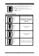

8S RS232/422/485 PCI Express Expansion Module
6
Please note that this product does NOT support hot-plug
feature by means of the Expansion Cable. You can NOT connect or
disconnect the expansion cable unless you power off your system
first.
1. Turn OFF the system power before installation!
2. Remove the chassis cover from your computer
3. Locate an unused PCI Express slot (typically white and smaller)
and remove the corresponding slot cover from computer
chassis.
4. Plug the PCIe add-in Host Adapter Card to the unused PCI
Express expansion slot and attached its card bracket to the
computer chassis screw.
5. Put the chassis cover back on the computer.
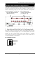
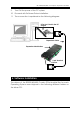
6. Install one end of the DVI-like Expansion Cable to PCIe add-in
card’s connector and the other end to the Expansion Box’s.
Waring!!
Since the Expansion Cable’s
connector has the same form factor as the standard DVI
connector, however, their signals are different, please do NOT
connect the Expansion Cable to neither your LCD monitor nor
your Video Graphic cards.
7. The Module Box is powered by the DVI cable from the PCIe Host
Adapter by factory default. In this case, you don’t have to
connect any DC power to the 2-pin terminal blocks on the
Module Box. Unless your host PC cannot support enough power
for the Module Box through the cable, the 2-pin terminal blocks
must be left unconnected in most cases.
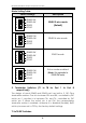
8. If you are connecting a RS232 device to the Module Box, then
the 3 RS232 pins on the terminal blocks are required. The RS232
mode does not need any extra DIP switch settings, simply
connect to the terminal blocks’ pin 5, 6 and 7 and left the rest
pin 1~4 unconnected. Each port can only work in one mode at
the same time. The RS232 mode is not set by DIP switches.
Instead, it is automatically supported by the separate connector
pins.
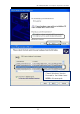
5. Installing the Expansion Module Box
DVI