MicroMeter Optical Power Meter Operations Manual Firmware Version 1.
Table of Contents Preface Why Use An Optical Power Meter? Checking the MicroMeter Firmware Version ii ii ii Unit 1 - Introduction Description Applications General Features Keyboard Entry Method 1-1 1-1 1-2 1-2 Unit 2 - Meter Functions Power ON Power Units Supported by the MicroMeter Wavelengths Supported by the MicroMeter “Zeroing” the MicroMeter Monitor Mode Main Menu Meter Setup Manual Reference Method Stored Data Menu Power OFF 2-1 2-1 2-2 2-2 2-2 2-3 2-3 2-4 2-5 2-5 Unit 3 - Fiber Certification O
PREFACE Why Use An Optical Fiber Power Meter? Standards organizations such as the TIA or the ISO/IEC provide performance standards that the cabling plant must adhere to in order to support high-speed protocols such as Gigabit Ethernet. Fiber can be tested against these standards, ensuring that it is able to handle the high amount of traffic with a maximum amount of reliability. These standards organizations also provide standards for administration of the cabling plant.
UNIT 1 INTRODUCTION Description The MicroMeter is a high accuracy, high resolution, microprocessor controlled optical power meter. The meter has a wide dynamic range making it ideal for both single and multi-mode fiber testing. It has an attractive handheld case, a backlit graphical liquid crystal display, and 18-key keypad for easy data entry. The meter comes with a small state-of-the-art UNIVERSAL adapter that is fully reliable for the use of ST, SC, FC or any 2.
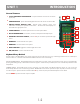
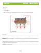
UNIT 1 INTRODUCTION General Features 1 2.5mm UNIVERSAL ADAPTER PORT - accepts standard 2.5mm ferrule connectors (ST, SC, FC). 2 1 6 2 COMPUTER PORT - port for downloading data from the meter to a PC via serial cable. 3 LIQUID CRYSTAL DISPLAY (LCD) - displays power readings, menus, and information necessary for operation of the meter. The elements of the display are discussed in the appropriate units. 3 4 FUNCTION KEYS - activate the options on the Function Options Menu.
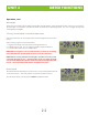
UNIT 2 METER FUNCTIONS Operation Power On 1) Press the ON button. 2) After a few seconds, a screen will appear that looks like the one below, which is called Immediate Mode. Power Units Power Measurement Link Name Run Number -20 .45 dBm ABS 82 68% ............
UNIT 2 METER FUNCTIONS Operation, cont. Wavelengths Measurements can be taken for four different wavelengths in the MicroMeter. These wavelengths are 850, 1300/1310, and 1550nm. All wavelengths are traceable to the National Institute of Standards and Technology (NIST). The user may toggle through these wavelengths by pressing F3. “Zeroing” the MicroMeter in Immediate Meter mode This function allows the user to set references for each wavelength for fiber attenuation testing.
UNIT 2 METER FUNCTIONS Operation, cont. Main Menu Advanced meter functions can be configured from the Main Menu. Options 1 through 4 are listed in a step-by-step order for certifying fiber links and will be explained in greater detail later in this manual. Option 5 is explained below. Press MENU to enter the menu. <1>SELECT LINK - This option allows the user to select the fiber link to be used for the test, as well as editing its descriptive name and test date.
UNIT 2 METER FUNCTIONS Operation, cont. Manual Reference Method-recommended for advanced users only The Micro can be used to certify fiber links (shown in detail in the next unit) or to measure link loss by setting a manual reference. The manual reference method is used to measure the actual loss in a fiber link, and it is recommended that only those users who are very familiar with calculating link budgets should use this method. 1) From Immediate Mode, press MENU to enter the MAIN MENU.
UNIT 2 METER FUNCTIONS Operation, cont. Stored Data Menu The STORED DATA menu allows the user to manipulate data that is stored in the MicroMeter. <1>VIEW/EDIT/LOAD - this option allows the user to view, edit, or load any data point that was previously stored in the MicroMeter. The VIEW/EDIT/LOAD screen initially loads with the first data point stored in memory.
UNIT 3 FIBER CERTIFICATION Overview The whole purpose of fiber certification with the MicroMeter is to save data points using a standards-based reference point and produce professional-looking reports for the customer. The MicroMeter is capable of storing up to 1000 data points with user-configurable fiber labels, and can certify up to four separate fiber links against the EIA/TIA 568 standard.
UNIT 3 FIBER CERTIFICATION Fiber Certification, cont. STEP 1 - SELECT LINK 1-1) Press MENU to enter the MAIN MENU. 1-2) Press 1 to SELECT LINK. 1-3) At the STORED LINKS menu, the currently loaded link is denoted by an asterisk. Scroll through the list of links by pressing F1 to highlight the link to use. Press F3 to edit the name and the testing date of the selected link. EDIT LINK 1-3a) Give the link a descriptive name. Press F1 to edit the name. Press DONE to continue. 1-3b) Enter the date of the test.
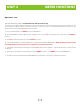
UNIT 3 FIBER CERTIFICATION Fiber Certification, cont. wavelength as in step 2-7. Repeat steps 2-7 through 2-10 for all wavelengths the user is setting a reference for. 2-12) Press F1to continue. The user will be returned to the MAIN MENU. STEP 3 - TAKE READINGS 3-1) Press 3 to TAKE READINGS. The screen shown on the right will appear. Take a moment to familiarize yourself with this screen. Power Units Power Measurement Fiber Link Name Fiber ID -20 .
UNIT 3 FIBER CERTIFICATION Fiber Certification, cont. 4-4) Connect the MicroMeter to the PC via the download cable supplied with the meter. 4-5) Start the Reporter software on the PC. 4-6) Click the Download option on the menu bar, or the Download button on the button bar. The data points that are stored in the meter will appear in the Reporter window. Press DONE to return to the STORED DATA menu, and press DONE again to return to the MAIN MENU.
UNIT 4 APPENDICES Appendix A - Decibel Review The MicroMeter meter has a decibel(dB) range that spans 75dB. The whole purpose of your meter is to measure light energy in decibels. But what exactly is a decibel? It is not uncommon for a technician to be using an optical power meter and not understand what a decibel really is. If you struggle a little with this review, you will find the concept not so threatening.
UNIT 4 3 APPENDICES APPENDICES Appendix A - Decibel Review, cont. There are other decibels to consider. The decibel we previously described is”dB” is called relative. This is because it is a ratio as was explained. With ratios there is no way to tell what absolute value we had at the start or end of a link. To solve the problem we can always reference our optical power to a fixed value of one milliwatt (1 mW). One milliwatt of power will replace the denominator of our equation.
UNIT 4 3 APPENDICES APPENDICES Appendix C - Glossary, cont. Bandwidth. The transmission capacity of a system. Buffering. 1. A protective material extruded directly on the fiber coating to protect the fiber from the environment (tight buffering). 2. Extruding a tube around the coated fiber to allow isolation of the fiber from stresses on the cable (loose buffered) Buffer Tubes. Loose-fitting covering over optical fibers used for protection and isolation. Bundle.
UNIT 4 3 APPENDICES APPENDICES Appendix C - Glossary, cont. Equipment Room. A centralized space for telecommunications equipment that serves the occupants of the building. Equipment housed herein is considered distinct from a telecommunications closet because of its nature or complexity of the equipment. Frequency. Of a periodic wave, the number of identical cycles per second. Usually expressed in Hertz. Fresnel Reflection.
UNIT 4 3 APPENDICES APPENDICES Appendix C - Glossary, cont. Multi-mode Fiber. A type of optical fiber that supports more than one propagating mode. Numeric Aperture (NA). The number that expresses the light-gathering ability of a fiber. Optical Time Domain Reflectometry (OTDR). A method of evaluating optical fibers based on detecting backscattered (reflected) light. Used to measure fiber attenuation, evaluate splice and connector joints, and locate faults.
UNIT 4 3 APPENDICES APPENDICES Appendix D - MicroMeter Specifications Detector Type:------------------------------Calibrated Wavelengths:---------------------Measurement Range:--------------------------Accuracy:-----------------------------------Resolution:---------------------------------Battery Life:-------------------------------Connector Type:-----------------------------Operating Temperature:----------------------Storage Temperature:------------------------Size:---------------------------------------
UNIT 4 3 APPENDICES APPENDICES Appendix F - Cleaning and Care Instructions The MicroMeter is a sensitive piece of scientific equipment. Great care should be taken when handling and cleaning it. HANDLING TIPS 1) Do NOT drop any piece of scientific equipment, e.g. the MicroMeter. Damage may occur to the case or electronic components on the circuit board may become dislodged, and inaccuracy may occur. 2) Keep the meter in its neoprene case when not in use.
UNIT 4 3 APPENDICES APPENDICES Appendix G - Optional Accessories PR600 - Mini Serial Thermal Printer with Cable CB600 - Cable for PR600 Printer LE200ST - 850nm LED Source w/ST input LE210ST - 1300nm LED Source w/ST input LE210SC - 1300nm LED Source w/SC input LE220ST - 850nm & 1300nm LED Source w/ST input LS300FC - 1310nm Laser Source w/FC input LS300SC - 1310nm Laser Source w/SC input LS300ST - 1310nm Laser Source w/ST input LS310FC - 1550nm Laser Source w/FC input LS310SC - 1550nm Laser Source w/SC inpu
UNIT 4 3 APPENDICES APPENDICES Appendix H - Link Budget Calculation Worksheet Operating Wavelength Fiber Type Passive Cable System Attenuation Fiber Loss at Operating Wavelength (Distance x Fiber Loss) Total Cable Distance Individual Fiber Loss (at operating wavelength) Total Fiber Loss Connector Loss (Connector Loss x Connector Pairs) Individual Connector Loss Number of Connector Pairs Total Connector Loss Splice Loss (Splice Loss x Splices) Individual Splice Loss Number of Splices Total Splice Loss km
UNIT 4 3 APPENDICES APPENDICES Appendix I - Reference jumper setup Your test jumpers must be cleaned and inspected prior to using them for fiber link testing. You should have one jumper for the power meter side of the test, and one jumper for each of the connector ports on your light source. Make sure that these patch cords match the fiber under test (i.e. same fiber type, same core/cladding size, same connector type).