
Specifications

There are other decibels to consider. The decibel we previously described is”dB” is called relative. This is because it is a
ratio as was explained. With ratios there is no way to tell what absolute value we had at the start or end of a link. To solve
the problem we can always reference our optical power to a fixed value of one milliwatt (1 mW). One milliwatt of power
will replace the denominator of our equation.
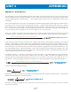
So when we are given a value of absolute power in dBm we know that it is the power relative to 1 mW
and we can calculate the actual power in mW if necessary. We can also compare values in dBm to each
other because they are relative to the same reference (1mW). However, we cannot compare values in dB
to each other because we do not know if they are relative to the same reference.
Appendix A - Decibel Review, cont.
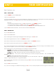
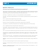
ABSOLUTE POWER IN dB
END OF LINK
=
10 LOG(
W
1 mW
)
Now that you have a clearer understanding of the decibel, we can begin to study the dynamic range feature of the
MicroMeter. The dynamic range of the MicroMeter is +5 to -70 dBm (or +25 to -70 dBm, but what exactly does this
mean?
Dynamic range is defined as the difference between the minimum and maximum power levels that a photodetector can
reliably sense, and still maintain acceptable accuracy. In the case of the MicroMeter, the dynamic range is 75dB.
Any power level reaching the detector that is greater than +5 dBm is too powerful to accurately measure. Likewise, any
power level below -70 dBm will be too weak to be sensed.
Power levels within the dynamic range produce acceptable readings. It is interesting to note that the MicroMeter remains
accurate over the upper 96% of the 75 dB dynamic range and then gets progressively worse as the power levels drop off.
The limits of dynamic ranges depend on certain factors. The minimum level depends on the sensitivity of the receiver. The
sensitivity of the receiver can be increased by using different materials, such as germanium (Ge) or indium/
gallium/arsenide (InGaAs). The characteristics of these materials allows the detector to be responsive at lower power
Appendix B - Dynamic Range Review
Absorption. The loss of power in an optical fiber, resulting from conversion of optical power into heat and caused principally by
impurities, such as transition metals and hydroxyl ions, and also by exposure to nuclear radiation.
Acceptance Angle. The half-angle of the cone within which incident light is totally internally reflected by the fiber core. It is equal to
arcsin (NA).
Attenuation. A general term indicating a decrease in power from one point to another. In optical fibers, it is measured in
decibels per kilometer at a specified wavelength.
Appendix C - Glossary
4-2
UNIT 3
APPENDICES
APPENDICESUNIT 4