User's Manual Digital AC Clamp Meter Model 38390
WARRANTY EXTECH INSTRUMENTS CORPORATION warrants this instrument to be free of defects in parts and workmanship for one year from date of shipment (a six month limited warranty applies on sensors and cables). If it should become necessary to return the instrument for service during or beyond the warranty period, contact the Customer Service Department at (781) 890-7440 ext. 210 for authorization. A Return Authorization (RA) number must be issued before any product is returned to Extech.
INTRODUCTION Congratulations on your purchase of Extech’s 38390 AC Clamp Meter. This autoranging clamp meter measures AC Current to 400A, DC/AC Voltage, Resistance, and Continuity. Proper use and care of this meter will yield years of reliable service. SAFETY Safety Symbols This symbol, adjacent to another symbol or terminal, indicates the user must refer to the manual for further information.
Safety Precautions WARNING: Improper use of this meter can cause damage, shock, injury or death. Read and understand this users manual before operating the meter. 1. 2. 3. 4. 5. 6. 7. Always remove the test leads before making current measurements. Always remove the test leads before replacing the batteries. Inspect the condition of the jaws, test leads and the meter for any damage before operating the meter. Repair or replace any damage before use. Do not exceed the maximum rated input limits.
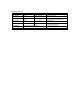
SPECIFICATIONS Function AC Current Range 40.00A 400.0A 400.0V 600V 400.0V 600V 0.3 to 400 Ω Accuracy ± (2% + 15 digits) Remarks Frequency: 50/60Hz; 660A overload protection AC Voltage ± (1.5% + 10 digits) Frequency: 40Hz to 450Hz; Input Z: 1MΩ; 660Vrms OL protect DC Voltage ± (1% + 5 digits) Input Z: 1MΩ; 660V overload protect Resistance ± (1% + 5 digits) -1.1 to -1.3V open circuit; 600Vrms overload protect Continuity -1.1 to -1.
Conductor Size Operating principle Battery type Battery Life Auto Power off Range Selection Display Overload Indication Low Battery Indication Environmental conditions Operating Temperature/Humidity Storage Temperature/Humidity Dimensions Weight 0.9" (23mm ) maximum Dual slope integration 2 x 1.
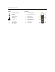
METER DESCRIPTION Front panel Symbols AC Current or Voltage 1. Jaw opening trigger DC Voltage 2. Function switch (OFF, A, V, Ω) Continuity H Display Data Hold 3. COM input jack A Auto Range 4. Transformer Jaws Low Battery icon 5. DATA HOLD key 6. AC/DC Selector key Units V Ω A Volt (voltage) Ohm (resistance) Amps (current) 7. LCD Display 8.
OPERATING INSTRUCTIONS Precautions 1. 2. 3. Ensure that the selected meter function matches the measurement to be taken. If the measured current is higher than the range selected for long periods, overheating may occur compromising the safety and the operation of the meter’s internal circuits. To avoid discharge risks and erroneous readings, do not measure current on high voltage conductors (>600V).
DC and AC Voltage Measurements 1. Set the Function Switch to the V position. 2. Press the AC/DC key (directly below the HOLD key) to select AC or DC Voltage. The meter will show the selection with an AC or DC symbol (upper left side of LCD). 3. Insert the black test lead to the COM input jack and the red test lead to the V jack. 4. Connect the test leads in PARALLEL with the circuit to be measured. 5. Read the measured value from the LCD display.
Data Hold Press the HOLD key momentarily to freeze the present reading on the LCD. "H" will appear in the display. Press the HOLD key again to return to normal operation.
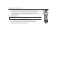
MAINTENANCE WARNING: To avoid electrical shock or damage to the meter, keep moisture from entering the meter housing. Also, remove the test leads before opening the meter housing. Cleaning Periodically wipe the case with a damp cloth and mild detergent. Do not use abrasives or solvents. Battery Replacement When the low battery symbol appears on the LCD, replace the meter’s two button-batteries. 1. Remove power and remove test leads from meter 2.
Battery Replacement Illustrations 1. 2. 3. 4. 5.