EXTECH DATA SYSTEMS SERIES 2000 + SERIES 3000 DEVELOPER’S GUIDE VERSION: 4B DATE: October 2000 Part Number: 7A060028DG Page 1
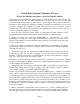
Extech Data Systems Celebrates 10 Years Design and Manufacture Battery Operated Portable Printers Extech Data Systems, the Portable Printing Division of Extech Instruments, started Engineering development of a new line of portable instrumentation in 1988, just ten years ago. The first products from this development, a portable battery operated printer and a portable modem were introduced in 1989.
in magnetic card reader allows fans to order directly from their seat. The order is radioed to the kitchen, filled and delivered right to the seat.
§ Introduction of vehicle mount printers, operating from the vehicle battery, for EFTPOS systems Additionally, the design of our products allows easy modification as needed to satisfy customer needs. We pride ourselves on responding to specific customer requirements. Over the past four years the needs of many of our major customers demanded that we develop new variations of printers for them.
Section 1 … Preparing the Printer Introduction This guide summarizes the programming, operating and maintenance features of the SERIES 2000T, Series 2000i and Series 3000T Extech printers. This section should be included in your operating guide for the final users of the printer. Initial preparation of the Printer § § § § You must charge the battery cartridge before you can operate the printer.
§ Press the switch to turn on the printer. Manually Installing Paper (figure 4) … Thermal Printers § To unlock the top hinged cover, place each thumb on the grooved sections indicated in the figure at the rear of the cover. Press the two locking ribs located at the rear of the printer to release the first lock; raise the hinged cover to open. Press on the two locking arms to allow the cover to fully open and provide access to the paper area.
§ Place the wedge of the leader just under the roller in the print-head; the printer will sense the paper and advance it through the print-head. If you experience difficulty, press the switch. § Place roll in the printer. § Feed the leading edge of the paper into the slot of the hinged cover § Lower the hinged cover and lock. § Pull the 4 inches of paper forward against the teeth of the paper tear bar and pull to either side to tear off the paper.
Installing Ribbon (figure 1) … Impact Printers § Unlock and raise the top hinged cover as described above. Remove the worn out ribbon by pressing with one finger at the location labeled “EJECT” on the ribbon cartridge. § Insert the new ribbon in place and press at the extreme ends of the ribbon cartridge to secure it in place. With your thumb, tighten the ribbon, by rotating clockwise, the ribbed wheel located on the front of the ribbon cartridge.
§ Red Ÿ Indicates printer paper out. Ÿ Indicates print head lever is up. Ÿ Indicates incorrect read with magnetic card reader. Ÿ § Indicates printing with low power (printing not possible). Ÿ Flashing Indicates printer is paused; to continue printing current receipt, press or to clear print buffer press .
Section 2 … Serial Communications RS 232 Communication Interface (Standard) § Eight position dip switch, located to the left of the paper roll, is used to select and set the serial RS232 interface. The printer reads these switches once on initial power-up (see below). § Proper Baud Rate and protocol settings are required to communicate with a host computer. The standard factory setting is 19,200 BAUD, 8 DATA BITS, NO PARITY BIT, and one STOP BIT, all switches in off position.
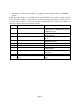
RS 232 Communication Interface (Special / Impact Only) § The standard factory setting for this version is 9,600 BAUD, 8 DATA BITS, NO PARITY BIT, and one STOP BIT, all switches in off position. To make changes use the table below: Dip Switch Function 1&2 Baud rate SW1 SW2 9,600 off off 4,800 on off 2,400 off on 1,200 on on No.
RS232C Connections § The RS232C Interface signals for the S2000T Series printers are terminated on a 6 PIN RJ type data connector located at the back of the printer (Figure 3). § Six connections are provided from the Serial Interface to the host computer for proper operation of this option. § The table below lists the Serial Interface signals and pinouts on the RJ connector. § A minimum of two connections are required for operation, RXD-pin3 and Common-pin1.
SERIAL IrDA Communication Interface § This section summarizes the operating features of the Extech S2000T printer series with built in Infrared Data Receiver Interface (IrDA) § The IrDA Interface is designed for reception of serial data and no interconnecting cables are required for data transfer. It conforms and exceeds Infrared Data Association protocol specifications for secondary station, as specified in IrDA-1 standard.
Section 3 ... Battery Battery Recharging Operation § The Extech Printers features an internal fast battery recharge system. This system is designed to fast charge the battery cartridges in 90 minutes using 120V/9VDC/1.0A power adapter (PN# 152120). This adapter is designed for North American use. Both 220V (PN# 152320) and 240V (PN# 152340) versions are available for international use. § The battery voltage, temperature and maximum charge time are monitored during battery recharge cycle.
Section 4 ... Control and Character Set Control Characters § The printer has a set of commands which provide control of printer functions. The printer also provides response commands informing the user of the printer status.
Character XOFF Control ^S Hex/Dec 13/19 NORM AUXOFF ^T ^U 14/20 15/21 CANCEL ^X 18/24 ESC ^[ 1B/27 EXTEND ^\ 1C/28 EXTEND OFF ^] 1D/29 CONTROL ACTION Printer receiver is off Printer to Host: Print Buffer is full. Host to Printer: Host transmitter off. Return to normal print Printer to Host: printer is off transmitted to host before power down or paper out Cancel and reset printer If received, print buffer is reset and printer placed in initial power-up default settings.
Section 5 ... S 2000i Character Sets Resident Character Sets (S2000i) § There are 3 resident fonts for the 2000i. CHARACTER NAME MSP FONT International character set (Standard) Hebrew character set IBM compatible character set ESC+F+1 ESC+F+2 ESC+F+3 § The characters are formed using a 5x7 matrix. The first 127 entries in the font table are ASCII characters.
§ The Large characters are formed by using a 10x14 dot matrix. Large character print is selected if both Expanded and Extended print is selected. To reset large print to normal print, Expanded and Extended prints must be disabled or Carriage return sent to printer. Dot Addressable Graphics § The SERIES 2000i can print special symbols, graphs and characters if operated in the Dot Addressable Graphics mode. § In the Dot Addressable Graphics mode of operation, the printer prints one dot line at a time.
Section 6 ... S 2000T Character Sets Resident Character Sets § The Series 2000T has two resident character sets, the standard international and IBM compatible character sets. For both resident character sets, the lower 128 bit values follow the ASCII standard. Characters 0 through 31 are reserved ASCII printer control characters, while 32 through 127, are the ASCII alpha numeric upper lower case characters. The extended characters are from 128 to 255.
24 cpi bold 48 8x21 ESC+F+7 ESC+k+5 21 cpi bold 42 9x21 ESC+k+4 19 cpi normal 38 10x21 ESC+k+3 16 cpi normal 32 12x21 ESC+k+2 12 cpi normal 24 16x21 ESC+k+1 12 cpi bold 24 16x21 ESC+k+0 § Both fonts are monospaced, meaning for each character pitch selected (cpi) all the characters are exactly the same width, making page layout easy to control. The MSP compatible dot matrix font are based on a single 6x16 font table.
Section 7 ... Operating in MS-DOS World For proper operation of the S2000T printers in the DOS environment, the following are required: FOR SERIES 2000T - Serial Printer Version § Use DOS print command to print, or Write Direct to printer port. § Set the PC's communication baud using DOS MODE command: Printer and PC baud rate and parity have to match.
Section 8 ... Supervised Mode Operation § The S2000T printers can be operated in a supervised mode. A single byte supervision command <0x02> (^B), allows polling the status of the printer.
Printer battery level status § For Example, if the printer battery voltage is at 6.58 volts the following battery status string is returned upon receiving a <0x02> poll command. <0x1B> <0x4D> <0x00> <0x36> <0x35> <0x38> § <0x0D> <0x0A> The internal battery voltage can vary from 5.00 (depleted) to 7.25 (full charge) volts.
Section 9 ... Auto Power Down Feature § In order to conserve battery life the S2000T printer features a auto power down timer. The power down timer defaults to 20 seconds on initial power up. § The auto power down timer can be set by sending recognized command string or disabled by activating the input line or setting the auto power down timer to zero.
Section 10 ... Firmware V1.09 (S2000T) Control Characters § Control characters are from 01 through 31. Character EOT Control ^D Hex/Dec. 04/04 BS ^H 08/08 HT ^I 09/09 LF ^J 0A/10 VT ^K 0B/11 FF ^L 0C/12 CR ^M 0D/13 SO ^N 0E/14 SI ^O 0F/15 XON ^Q 11/17 AUXON ^R 12/18 XOFF ^S 13/19 NORM AUXOFF ^T ^U 14/20 15/21 CONTROL ACTION End Of Text Printer sends an EOT character when buffer is empty. This is used to tell the host that printer is in idle mode.
Character CANCEL Control ^X Hex/Dec 18/24 ESC ^[ 1B/27 EXTEND ^\ 1C/28 EXTEND OFF ^] 1D/29 CONTROL ACTION Cancel and reset printer If received, print buffer is reset and printer placed in initial power-up default settings. Escape Escape character precedes graphics and printer operating modes. Refer to escape command section. Extended print All characters following this command are printed double high (5x14).
Issuing Escape Commands § Many 2000T printer properties may be modified by issuing escape commands. The following pages detail these commands using conventions detailed here: Symbol Purpose The next character is a control character , , … Control characters <‘A’>, <‘P’>, <‘Q’>… Single quotation marks (‘’) denote constant ASCII characters. , … Italics denote variable bytes in control string. 0x00, 0xAB, 0x1F… Hexadecimal representation of a number.
COURIER FONTS ASCII range 32-255 <‘k’> (n = {‘0’ to ‘5’}) Number of columns Matrix size Command Character pitch 48 8 x 22 <‘k’> <‘5’> 25 CPI 42 9 x 22 <‘k’> <‘4’> 23 CPI 38 10 x 22 <‘k’> <‘3’> 20 CPI 32 12 x 22 <‘k’> <‘2’> 17 CPI 24 16 x 22 <‘k’> <‘1’> 13 CPI 24 16 x 22 <‘k’> <‘0’> 13 CPI BOLD Print Contrast Adjust Commands <‘P’> (n = {‘0’ ..
8-Bit Dot Addressable Graphics 8 Bit Graphic Line(s): <‘V’> n1: 8 bit integer indicating the number of 48 byte graphic lines to be received. n2: ignored. Graphic Character set: From 00-FF Hex using bits 0-7 (Bit seven left) Perform n <.
Reset Line Counter: <‘P’> <‘?’> Print Clock/calendar: <‘P’> (‘@’, ‘A’ ..‘Y’.
Printer Mode On-line mode: <‘P’> < ‘#’> Characters printed as received. Buffer mode: <‘P’> <‘$’> Characters buffered until receipt of <‘D’>. Future Features Font Download Load a character: <‘D’> n1: Bank to save the character in {0x00,0x01,0x02} n2: character code {32 ..
Section 11 ... Firmware V1.0 (3000T) Control Characters § Control Characters are from 01 through 31. Character EOT Control Hex/Dec. ^D 04/04 CONTROL ACTION End Of Text Printer sends an EOT character when buffer is empty. This is used to tell the host that printer is in idle mode. BS ^H 08/08 Back Space Remove previous character in print buffer. HT ^I 09/09 Horizontal Tab Tab to 5,9,13,17,21,25,29,33,37 or to the beginning of next line. LF ^J 0A/10 Line Feed Advance to beginning of next line.
§ Many 3000T printer properties may be modified by issuing escape commands. The following pages detail these commands using conventions detailed here: Symbol Purpose The next character is a control character (see table 11.1) , , … Control characters (see table 11.1) <‘A’>, <‘P’>, <‘Q’>… Single quotation marks (‘’) denote constant ASCII characters , … Italics denote variable bytes in control string 0x00, 0xAB, 0x1F… Hexadecimal representation of a number.
COURIER FONTS ASCII range 32-255 <‘k’> n = {‘0’ .. ‘6’} Number of columns Matrix size Command Character pitch 72 8 x 22 <‘k’> <‘5’> 24 CPI 64 9 x 22 <‘k’> <‘4’> 19 CPI 57 10 x 22 <‘k’> <‘3’> 19 CPI 48 12 x 22 <‘k’> <‘2’> 16 CPI 36 16 x 22 <‘k’> <‘1’> 12 CPI 36 16 x 22 <‘k’> <‘0’> 12 CPI BOLD 24 24 x 22 <‘k’> <‘6’> FAST COURIER FONTS 8 CPI ASCII range 32-255 <‘K’> n = {‘0’ ..
6-Bit Dot Addressable Graphics The printer will operate in 6-Bit Dot Addressable Graphics mode on receiving the Esc-G graphic command. While in this mode the printer prints one dot line at a time on receipt of 96 graphic characters or LF command. The LF command advances the paper by one (0.25mm) dot line. Each horizontal graphic dot is made from 1x6 dot cells; the total number of dot cells per line is 96, corresponding to the 576 total dots per line capacity.
Battery Voltage status: <‘V’> <4 ASCII digits> Command: Power down: <‘M’> <2 ASCII digits> <‘0’> Print Battery voltage: <‘P’> <‘^’> Magnetic Card Reader (MCR) Enable MCR: <‘M’> <2 ASCII digits> Disable MCR: <‘C’> (For details of MCR see Section 14) Clock/Calendar and Line Counter Set Clock/Calendar <‘P’> <‘s’> < 12:30:00 12/12/98 > Enable Auto Clock/calendar print: <‘P’> <‘>’> Disable Auto Clock/cale
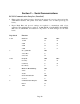
0x4E (‘N’) X 0x4F (‘O’) 0x50 (‘P’) X X 0x51 (‘Q’) 0x52 (‘R’) X X X X X X X 0x53 (‘S’) 0x54 (‘T’) X X X X 0x55 (‘U’) 0x56 (‘V’) X X X 0x57 (‘W’) 0x58 (‘X’) X 0x59 (‘Y’) X X X X Printer Mode: On-line mode: <‘P’> < ‘#’> characters printed as received Buffer mode: <‘P’> <‘$’> characters buffered on receipt of <‘D’> Page 37
Operating Features: New and Modified Version 0.95 § Modified contrast control Version 0.96 § Increased torque on auto paper load Version 0.
Version 0.99 § Code 39 bar-code print Bar-code alone: <‘z’> Bar-code with text: <‘Z’> ‘z’ print bar-code only ‘Z’ prints bar-code and ASCII visible n1 bar-code type: ‘1’ - code 39 n2 number of characters in data array {0x01 .. 0xFF} L § height of bar-code printed in Code 39 specification: Description: Each symbol starts with Leading Quiet Zone, followed with Start Symbol, Data Symbols, ending with Stop Symbol and Trailing Quiet Zone.
Version 1.02 § Enhanced Logo Download Print Logo: <’L’> <’g’> n = the order # of logo in SRAM. Record Logo: <’L’> <’G’> n = ??????xx binary where xx determines which of four locations to record logo to. Example: n = {0x00, 0x01, 0x02, 0x03} is the same as n = {0x30, 0x31, 0x32, 0x33} if n = 255: recording halts Version 1.
Paper Found: <‘Q’> <0x3F> <0x3F> n1 and n2 are the high and the low nybble, respectively, describing how many (0.25mm) dot lines were required to find Q-Mark. Each nybble is or'ed with 0x30. Paper Not Found: <‘Q’> <0x30> <0x30> n1 and n2 are the high and the low nybble, respectively, describing how many (0.25mm) dot lines were processed . Each nybble is or'ed with 0x30. § Form Loading Load Form: <‘L’> <‘T’> n {0x00 ..
Section 12 ... Magnetic Card Reader Introduction Ÿ An optional Magnetic Card Reader is available for the S2000T series printers. This option is designed to read Magnetic Cards conforming to ISO standards (ABA, IATA, MINTS and THRIFT), convert the encoded signals to ASCII format and transmit the information to the host computer or terminal. Ÿ Two Types of Magnetic Card Reader Heads are available. The part number, Model number and functional description of each type are summarized below.
Recognized Magnetic Card command strings § Six Magnetic Card command strings are recognized by the printer, these commands are summarized in the table below: Magnetic Card Command String ESC - M - nn - 1 - CR ESC - M - nn - 2 - CR ESC - M - nn - 3 - CR ESC - M - nn - 4 - CR ESC - M - nn - 5 - CR ESC - C Description Read Track1 only Read Track2 only Read Track3 only Read Track1 and Track2 simultaneously Read Track2 and Track3 simultaneously Cancel Read Turns off the LED (nn = ASCII "01" through "
§ The first three characters (/,1,/) flag the track number. The track data follows the third character, CR-LF terminates the
06 The Track Reader Escape command string transmitted by Host contained an invalid character. 07 Invalid Track Number is selected. Tracks "1", "2" or “3" can be selected. 08 Unsupported Track is Selected. Tracks "1", "2" or "3" can be selected. 09 "Cancel Request" error string is transmitted if Host cancels Magnetic card read in process. Magnetic Card Reader Operation in IrDA Mode § The way we handle the magnetic card data is the same as for printing data.
Sample Interface Program in C #include // MSC Standard I/O #include // C Run-Time Interrupt Driven Comm #include // C Run-Time Video Display Functions #define PRINTSPECS CM_SERIALFSM | CM_9600BAUD | CM_NOPRTY | CM_8BITS| CM_1STOP void readtrk( int ); void exit( void ); char buf[80]; // Rcv'd data buffer. char *cp = buf; // Next buffer loc to use.
Section 13 ... Extech IR-XMODEM Protocol § This is a proposed protocol for bi-directional data transfer through an Infrared channel. The protocol is based on packet transfer utilizing checksum error detection. Format of the data packet is shown below: SOH (0x01) § SEQ CSEQ ...DATA [128 Bytes]... Checksum When powered on, the Extech printer will default to slave mode, requesting to receive packets (sending a NAK character every 10 seconds).
Section 14 ... Troubleshooting Guide PROBLEM POSSIBLE CAUSE SOLUTION Printer will not turn on Discharged Battery Recharge battery overnight. Charge LED not lighting when AC adapter is plugged in. No AC power or AC adapter defective Check AC outlet or adapter (note: battery pack may be fully charged) Battery not charging. Battery incorrectly installed or Check battery installation and no AC. AC adapter Battery dead Paper not feeding.
Extech Data Systems Testing Power and Charging Circuits for MPP III Printer Test all printers, before returning to Extech, using the following procedure. This will ensure the fault is with the printer and not some other part of your system. § Install a fully charged battery (measuring 5.45 VDC) § To ensure a fully charged battery, we recommend you purchase a battery charger from us (Part # 767500, cost $150.00). The battery charger trickle charges 4 batteries at a time.
If the amber CHARGE light comes on indicating charge circuit is OK.
Section 15 ... Regulatory Notes FCC Part 15 Class B This equipment has been tested and found to comply with the limits for a Class B digital device, pursuant to Part 15 of the FCC rules. These limits are designed to provide reasonable protection against harmful interference in a residential installation. This equipment generates, uses and can radiate radio frequency energy and, if not installed and used in accordance with the instructions, may cause harmful interference to radio communications.