USER MANUAL 10KV Digital High Voltage Insulation Tester Model MG500
Introduction Thank you for selecting the Extech Instruments Model MG500. This device is shipped fully tested and calibrated and, with proper use, will provide years of reliable service. Please visit our website (www.extech.com) to check for the latest version of this User Guide, Product Updates, and Customer Support. Safety International Safety Symbols This symbol, adjacent to another symbol or terminal, indicates the user must refer to the manual for further information.
CAUTION! READ THE MANUAL Follow the instructions in the Manual for every measurement type. Read and understand the general instructions before attempting to use this instrument. SAFETY CHECK Before using the tester check the condition of the test leads. The test leads must be free of cracks or any damages and must be insulated. Always disconnect the test leads when changing the batteries Always double check the lead connections before making any measurements.
Features Insulation Resistance Testing This digital insulation resistance tester will measure insulation resistance from 800k ohms to 500G ohms using Dynamic Auto‐ranging technology. Test voltages range from 500V to 10kV in 500 Volt steps. This instrument also employs an Auto‐Discharge utility. DAR: Dielectric Absorption Ratio Testing The Dielectric Absorption is the ratio of the Insulation Resistance, measured at 60 seconds, divided by the Insulation Resistance measured at 30 seconds).
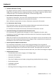
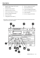
Description 1. Negative High Voltage (HV) Terminal (Earth Ground) 2. Dot Matrix Display window 3. GUARD connection Terminal 4. Positive High Voltage Line Terminal 5. 10KV test voltage preset button 6. Power OFF button 7. Voltage adjustment button (‐) 8. 5KV test voltage preset button 9. TEST START/STOP button 10. 2.5KV test voltage preset button 11. 500V test voltage adjust button (+) 12. Power ON button 13.
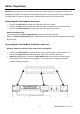
Meter Preparation Warning: Ensure that the circuit under test does not include devices or components that can be damaged by 10KVDC; such devices include power factor correction capacitors, low voltage mineral insulated cables, electronic light dimmers, ballasts and starters for fluorescent lamps. Connecting the Test Leads to the meter o Connect the Red (Line) test lead to the Red test jack on the meter. o Connect the blue lead (attached to the Red test lead) to the Blue test jack on the meter.
Operation Powering the meter Press the ON button to turn the unit on. Press the OFF button to turn the unit off. If the meter does not switch ON please check that fresh ‘C’ 1.5V alkaline batteries are installed in the battery compartment located at the bottom of the instrument. Insulation Resistance Testing Procedure Warning: The circuit under test must be completely de‐energized and isolated before making test connections. 1.
The EnersaveTM Mode EnersaveTM mode conserves battery life by performing a relatively short test (10 seconds). The TM Enersave mode is the default test mode. To bypass this mode and run a longer test (100 seconds) press and hold the TEST button for 3 seconds when starting a test. Do not hold for longer than 3 seconds as a DAR or PI test may start instead as explained in the next section.
Bargraph Voltage Display The bargraph represents the voltage present on the test leads as it rises, soaks, and decays. The bargraph appears on the lower left of the display window during a test. Automatic Under/Over Range Resistance Detect If the display shows the message “LOW M‐ohms”, the test should be interrupted immediately by pressing the TEST button. This message indicates that the insulation under test has broken down and the meter is trying to inject a high potential onto a short circuit.
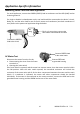
Application‐Specific Information Measuring Power Tools and Small Appliances For small appliances, connect the GREEN (EARTH) lead to conductors and the RED (LINE) lead to insulating material. For single or double insulated power tools, one lead should be connected to the device’s chuck, blade, etc. and the other lead to one of the AC power cord conductors (test both conductors in turn). Refer to the power tool application diagram below.
DC Motor Test 1. Disconnect the motor from the line. 2. To test the brush rigging, field coils, and armature, connect the RED lead to the grounded motor housing and the GREEN lead to the brush on the commutator. 3. If the resistance measurement indicates a weakness, raise the brushes off of the commutator and separately test the armature, field coils, and brush rigging by connecting one lead to each individually, leaving the other connected to the grounded motor housing.
Transformer Testing Transformer tests are performed with the transformer completely disconnected from the line and the load. Note that the case ground should not be removed. The five tests listed below will completely test a single‐phase transformer. Note that at least 1 minute should be allowed between each test. 1. High voltage winding to low voltage winding and ground 2. Low voltage winding to high voltage winding and ground 3. High voltage winding to low voltage winding (pictured at right) 4.
Insulator Measurement Considerations Insulators may get contaminated over time from a mixture of dust and moisture. Dust and moisture problems lower the resistance of the insulator as this resistance is in parallel with the insulator resistance. It is recommended that the insulator be measured first without the optional guard lead, to verify that the total resistance is high. Should the total resistance not be high enough, the contaminants should be removed or the insulator replaced.
Maintenance Battery Replacement When ‘REPLACE BATTERY’ appears on the display, replace the eight (8) 1.5V ‘C’ Alkaline batteries. 1. Ensure that the meter is powered down and that the test leads are not connected 2. Close the instrument cover and turn the instrument upside down 3. Remove the screw located on the bottom of the meter 4. Remove the battery compartment cover 5. Replace the eight batteries ensuring proper polarity 6.
Specifications Display 2 x 16 character alphanumeric multi‐function dot matrix (OLED) Test Voltage Ranges 20 ranges in 500V steps with automatic ranging. Preset buttons for 1KV, 2.5KV, 5KV, and 10KV; CAT III‐300V rated Insulation Resistance Measure Range/Resolution 800k ohms to 500G ohms (Auto‐ranging) DAR and PI tests Calculates Dielectric Absorption Ratio (DAR) Automatically. 1kohm resolution Calculates Polarization Index (PI) Automatically.