USER MANUAL Thermal Imager IR Thermometer MODEL IRC130
Table of contents 1 Introduction........................................................................1 2 Safety ................................................................................2 2.1 Safety Warnings and Cautions....................................... 2 3 Description.........................................................................3 3.1 Product Description..................................................... 3 3.2 Control Button Descriptions ....................................
Table of contents 8.11 8.12 8.13 8.14 8.15 9 Data Interface Specifications....................................... 21 Rechargeable Battery Specifications ............................ 21 Environmental Specifications ...................................... 21 Physical Specifications .............................................. 22 Included Equipment .................................................. 22 Warranty and Customer Support ......................................... 23 9.1 Two-Year Warranty .........
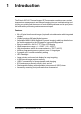
1 Introduction The Extech IRC130 Thermal Imager IR Thermometer combines non-contact temperature measurement and thermal imaging into one troubleshooting tool to help you quickly find the source of heat-related problems and to spot potential faults when performing maintenance and repair.
2 Safety 2.1 Safety Warnings and Cautions WARNING ⚠ This symbol, adjacent to another symbol indicates the user must refer to the manual for further information. WARNING The instrument’s IP54 rating is only in affect when the top flap (covering the USB-C jack) is completely sealed. Do not operate the instrument with the flap open, except for charging and PC interface.
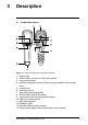
3 Description 3.1 Product Description Figure 3.1 Thermal Imager IR Thermometer Description 1. 2. 3. 4. Display area Return button (to back up in the menu system) Laser pointer button Up/Down Navigation buttons & Power (long press)/Menu (short press) button 5. Lanyard post 6. Accessory mount 7. High temperature lever switch 8. 80 x 60 pixel Lepton® IR camera 9. Laser pointer with circular target-spot assist 10. USB-C jack compartment 11. Spot thermal sensor 12. Flashlight (LED) 13.
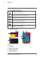
3 Description 3.2 Control Button Descriptions Long press to power ON or OFF Short press to access the menu system Return button. Back out to previous screen in menus Press to scroll upward in the menus Press to scroll downward in the menus Press and hold to use the Laser pointer Pull trigger to capture camera image TRIGGER Pull trigger to exit the menu system 3.3 Display Description Figure 3.2 IRC130 Displays 1. 2. 3. 4. 5. 6.
3 Description 7. Center spot cross-hairs 8. Laser Pointer active 9. Center spot temperature measurement #NAS100031; r.
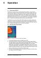
4 Operation 4.1 Powering the IRC130 The IRC130 is powered by a rechargeable lithium battery. Long press the power button (centre) to switch the unit ON or OFF. If the unit does not power ON, charge the battery by connecting to a 5V/1A rated AC wall charger (not supplied) using the supplied USB-C cable. The USB-C jack is located in the compartment at the top of the unit. Do not use the IRC130 while it is charging. When the top flap is closed, the unit is rated IP54 for encapsulation. See Section 7.
4 Operation 4. Use the Laser pointer to accurately target a spot. Press the Laser pointer button to switch ON the Laser pointer. The Laser pointer includes a circular spot indicating the area that is being monitored for temperature, utilizing DOE (Diffractive Optical Elements) technology. See the Laser pointer image example below in Figure 4.2. If the Laser beam does not appear when the button is pressed, check the menu system (under Device Settings) to ensure that the Laser is enabled. 5.
4 Operation 4.4 Visible Spectrum Camera Figure 4.3 Visible Spectrum Digital Camera Image 1. Long press the power button to switch the IRC130 ON. 2. Select the Visible Image mode in the menu system (under Image Adjustments/Image Mode). 3. Point the camera toward the test area and scan as desired. 4. View the image on the display, see Figure 4.3. 4.5 Capture, View, Transfer, Send, and Delete Camera Images 1. To capture a camera image to the IRC130 internal memory, pull and release the trigger.
5 Programming Menu System 5.1 Menu System Basics Short press the MENU button to access the menu system. Use the MENU button to switch settings ON or OFF, use the Return button to move to the previous screen, and use the arrows to scroll. In addition, the MENU button is used in some cases to confirm settings. Use the trigger to exit the menu system. 5.2 Main Menu • GALLERY: Press MENU to access the stored images.
5 Programming Menu System 1. Image Modes: Press MENU at IMAGE MODES and use the arrow buttons to select VISIBLE IMAGE or THERMAL PLUS VISIBLE IMAGE (MSX®). 2. MSX® Alignment: Adjust the alignment (so that the thermal image and the visible image line up accurately) as follows: While viewing the THERMAL PLUS VISIBLE IMAGE screen in the menu, press MENU to access the MSX® adjustment screen and then use the arrow buttons to adjust the alignment. Press MENU to confirm.
5 Programming Menu System 3. Colors: Press MENU at the colors menu and use the arrow buttons to select a color palette: Iron, Rainbow, White hot, Black hot, Arctic, or Lava. Press MENU to confirm selection. • SETTINGS: Press MENU to access the Settings sub-menu (see below): 5.3 SETTINGS Sub-Menu • MEASUREMENT #NAS100031; r.
5 Programming Menu System 1. Center Spot: Press MENU to enable/disable the display cross-hairs. The cross-hairs should be used as a reference only to identify the spot that is being measured for temperature. Use the Laser pointer for more accurate targeting. 2. Emissivity: Press MENU to open the Emissivity adjustment utility. Use the arrows to scroll through the presets (0.95, 0.80, and 0.60) and use the MENU button to select a preset.
5 Programming Menu System 1. Laser: Press MENU to enable/disable the Laser pointer. When enabled, you can use the Laser pointer button to switch ON the Laser pointer. Use the Laser pointer for accurate targeting of measurement spots. 2. Screen brightness: Use the arrows to select the desired display intensity (LOW, MEDIUM, or HIGH). 3. Auto Power OFF (APO): Use the arrows to scroll and MENU to select the desired APO time (5/15/30 minutes). Set to ‘Never’ to disable APO.
5 Programming Menu System 1. Temperature Unit: Use the arrows and the MENU button to select °C or °F. 2. Time & Date: Use the arrows to scroll and the MENU button to set the Time, Date, Time Format, and Date Format. 3. Language: Use the arrows to scroll and the MENU button to select a language. #NAS100031; r.
5 Programming Menu System 4. System Info: Scroll to desired topic: Model Number, Serial Number, Software Level, Revision, Battery status (%), and remaining Internal Storage Capacity. • GENERAL SYSTEM INFO: Press MENU to view compliance information. • FACTORY RESET: Follow the prompts to reset the User Settings back to Factory Default status. #NAS100031; r.
6 Field Firmware Updates The IRC130 includes a USB-C port in the top compartment. The USB port allows the user to update the system firmware by first downloading an update file from the FLIR website and then connecting the unit to a PC (using the supplied USB-C cable) to copy the file. Firmware updates are available from https://support.flir.com. NOTE The IRC130 is not 100% compatible with USB-C to USB-C cables. Use only USB-C to USBA cables. The supplied cable is USB-C to USB-A.
7 Maintenance 7.1 Cleaning Wipe the housing with a damp cloth as needed. Do not use abrasives or solvents. Clean the lenses with a high-quality lens cleaner. 7.2 Battery Considerations and Service The rechargeable lithium battery is not user-serviceable. Please contact us for service instructions: https://support.flir.com. For best results, charge the battery immediately after seeing a low battery indication using the supplied USB-C cable (with an AC wall charger, not supplied).
8 Specifications 8.1 Imaging and Optical Specifications IR resolution 80 x 60 pixels Digital image enhancement Included Thermal Sensitivity /NETD < 70 mK Field of View (FOV) 51° x 66 (H x W)° Minimum focus distance 0.89 ft. (0.3 m) Distance-to-Spot ratio 30:1 Dual range operation Range 1: < 752℉ (400℃) Range 2: > 752℉ (400℃) For Range 2, the high temperature lever must be engaged Focus Fixed Image frequency 8.7 Hz 8.
8 Specifications 8.4 Measurement Specifications Object temperature range -13℉ ~ 1202℉ (-25℃ ~ 650℃) Accuracy at ambient temperature: 15℃ ~ 35℃ (59℉ ~ 95℉) -13℉ ~ 32℉ (-25℃ ~ 0℃): ± 7.0℉ (3.0℃) 32℉ ~ 122℉ (0℃ ~ 50℃): ± 5.0℉ or ± 2.5% (±2.5℃ or ± 2.5%) whichever is greater 122℉ ~ 212℉ (50℃ ~ 100℃): ± 3.0℉ or ± 1.5% (± 1.5℃ or ± 1.5%) whichever is greater 213℉ ~ 932℉ (100℃ ~ 500℃): ± 6.0℉ or ± 2.5% (± 2.5℃ or ± 2.5%) whichever is greater 933℉ ~ 1202℉ (500℃ ~ 650℃ ): ± 7.0℉ or ± 3.0% (± 3.0℃ or ± 3.
8 Specifications Languages Czech, Danish, Dutch, English, Finnish, French, German, Greek, Hungarian, Italian, Japanese, Korean, Norwegian, Polish, Portuguese, Russian, simplified Chinese, Spanish, Swedish, traditional Chinese, Turkish Firmware updates User manageable (instructions included in this user manual) 8.7 Image Storage Specifications Storage media eMMC 4G Image storage capacity 50000 images Image file format JPEG with spot temperature metadata tag 8.
8 Specifications 8.11 Data Interface Specifications Interface USB USB type USB-C for data transfer and battery charging Not 100% compatible with USB-C to USBC cables. Use only USB-C to USB-A cables. USB standard USB 2.0 High Speed 8.12 Rechargeable Battery Specifications Battery type Rechargeable Lithium ion Battery voltage 3.6 V Battery operating time 5 hours scanning (medium brightness setting) 4.
8 Specifications Magnetic fields EN 61000–4–8 Class 3 Encapsulation IP54 (IEC 60529) Shock 25 g (IEC 60068–2–27) Vibration 2 g (IEC 60068–2–6) Drop Designed for 6.56 ft. (2 m) Safety CE/CB/EN61010/UL Environmental safety REACH Regulation EC 1907/2006 RoHS 2 Directive 2011/65/EC WEEE Directive 2012/19/EC JIS C 6802:2011 laser directive IEC 60825–1 class I laser directive FDA laser directive Humidity requirements IEC 60068–2–30 for operation and storage 8.
9 Warranty and Customer Support 9.1 Two-Year Warranty FLIR Systems, Inc. warrants this Extech brand instrument to be free of defects in parts and workmanship for two years from date of shipment (a six-month limited warranty applies to sensors and cables). To view the full warranty text please visit: https://www.extech.com/warranty. 9.2 Repair and Calibration Services FLIR Systems, Inc. offers calibration and repair services for the Extech brand products we sell.