EXTECH DATA SYSTEMS MSP/MPP II/III COMPACT PORTABLE PRINTER USER'S MANUAL VERSION: 2.
About this Manual Objective This User's Manual supplies the necessary information for installing and operating Extech MPP/MSP compact portable printer series. Contents Chapter 1: This chapter starts with the visual overview of your MSP/MPP printer series. Power, data, ribbon, paper and installation procedures are covered and supported with helpful diagrams. At the end of this chapter you are ready for the initial power-up and printer self-test.
NOTE: FCC Part 15 Class B This equipment has been tested and found to comply with the limits for a Class B digital device, pursuant to Part 15 of the FCC rules. These limits are designed to provide reasonable protection against harmful interference in a residential installation. This equipment generates, uses and can radiate radio frequency energy and, if not installed and used in accordance with the instructions, may cause harmful interference to radio communications.
Contents 1.0 INSTALLATION AND INITIAL POWER-UP 1.1 1.2 1.3 MODEL NUMBER UNPACKING YOUR PRINTER FRONT PANEL LED INDICATORS 1.4 1.5 MEMBRANE SWITCH PANEL DATA CONNECTOR 1.6 POWER INPUT 1.6.1 AC POWER ADAPTER 1.6.2 DC POWER CONNECTION (OPTIONAL) 1.6.3 INSTALLING BATTERY INSTALLING PAPER AND RIBBON 1.7 1.7.2 1.7.2 1.8 2.0 INSTALLING PAPER INSTALLING RIBBON INITIAL POWER-UP AND SELF-TEST OPERATING YOUR COMPACT PRINTER PART I 2.1 PRINTER CONTROLLER 2.2 PRINTER MECHANISM 2.2.
3.0 OPERATING YOUR COMPACT PRINTER PART II 3.1 3.1.1 3.1.2 3.1.3 3.1.4 3.1.5 3.1.6 3.2 3.2.1 3.2.2 3.2.3 3.2.
Chapter 1 Installation and Initial Power-Up 1.0 INSTALLATION AND INITIAL POWER-UP Thank you for selecting the Extech compact portable printer. The MPP/MSP printer series feature compact reliable, plain paper dot matrix printers capable of printing 24 through 42 columns and dot addressable graphics. Packaged in rugged Cycolac enclosure, it is designed for use as a table top or portable battery operated printer.
Chapter 1 Installation and Initial Power-Up 1.2 UNPACKING YOUR PRINTER When you remove the printer from its shipping box, make sure it is in good condition. The package also includes an AC power adapter, rechargeable battery pack, paper roll, a warranty registration card. If any of the components are missing, contact Extech or your distributor for assistance. Keep the packing material so you can repack the printer for storage or shipment.
Chapter 1 Installation and Initial Power-Up 1.4 MEMBRANE SWITCH PANEL Four membrane switches are provided on the left side of the MSP/MPP printers for various operator controls. The switches are labeled , , and . The functions performed by these switches are summarized below. or The or switch is used to turn printer power on. The green LED is illuminated, if printer is selected. The switch is used to advance the paper by one line.
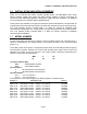
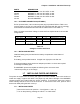
Chapter 1 Installation and Initial Power-Up PART # 152117 152220 153117 153220 151129 1.6.2 DESCRIPTION MSP/MPP II 110 VAC IN / 9VDC 1A Out MSP/MPP II 220 VAC IN / 9VDC 1A Out MSP/MPP III 110 VAC IN / 9VDC 2A Out MSP/MPP III 220 VAC IN / 9VDC 2A Out DC CAR ADAPTER DC POWER CONNECTION (OPTIONAL) For DC powered units, a two conductor power plug is provided. Refer to Table 1.0 to connect power to your DC unit. No internal fuse is provided with DC units.
Chapter 1 Installation and Initial Power-Up Tear and discard any paper remaining in the printer tray. Remove any paper remaining in the printer mechanism, using the switch. Do not REVERSE pull paper out of the printer mechanism - this will damage the printer mechanism Feed the new roll of paper into the printer paper slot using the switch. 1.7.2 INSTALLING RIBBON Remove the back cover (section 1.1 and figure 1.3).
Chapter 2 Operating Your Compact Printer 2.0 OPERATING YOUR COMPACT PRINTER PART 1 The MSP/MPP compact portable printer series is comprised of a microcomputer-based printer controller card, a printer mechanism module, a rechargeable battery pack and a high impact cycolac enclosure. 2.1 PRINTER CONTROLLER The MSP Serial printers use the Extech Part Number EX075 circuit board while the MPP Parallel printers use the Extech EX076 circuit board.
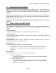
Chapter 2 Operating Your Compact Printer 2.2.1 PRINTER PAPER SPECIFICATION The MSP/MPP printers use 2.25" wide, .0027" thick and 1.12" diameter rolls of common calculator paper. Three types of paper may be used in the printer, Single ply roll, Two ply pressure sensitive roll, Label stock Custom Kiss-cut with perforation. Below is the specification for each type of the paper. PAPER TYPE Single Ply Two Ply Label stock 2.3 PART # WIDTH 757058 (5 rolls) 2.25"/57.5 mm 757135 (5 rolls) 2.25"/57.
Chapter 2 Operating Your Compact Printer 2.3.3 POWER-UP VIA DATA INTERFACE The MSP/MPP printer can be powered-up by transmitting a single character or activating or
Chapter 2 Operating Your Compact Printer 2.4 CONTROL CHARACTERS The printer has a set of commands which provide control of printer functions. The printer also provides response commands informing the user of the printer status. In this section, the recognized control characters and the corresponding printer actions are summarized. CHAR.
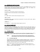
Chapter 2 Operating Your Compact Printer CHAR. AUXOFF CON T ^U CANCEL ^X H/D CONTROL ACTION 15/ 21 Printer to Host: printer is off transmitted to host before power down Cancel and reset printer If received, 2K print buffer is reset and printer placed in initial power-up default settings. Escape Escape character precedes graphics and printer operating modes. Refer to escape command section. Extended print All characters following this command are printed double high (5x14).
Chapter 2 Operating Your Compact Printer 2.6 CHARACTER SIZE Four character sizes can be selected through the communication interface, by sending control characters to the printer. Character Size Normal Expanded (Double Wide) Extended (Double Height) Large (double wide and double height) 2.6.1 Dot matrix size 5x7 10x7 5x14 10x14 NORMAL CHARACTER The Normal characters are formed using a 5x7 dot matrix. The printer defaults to 5x7 matrix Normal character size upon initial power-up. 2.6.
Chapter 2 Operating Your Compact Printer 2.7 DOT ADDRESSABLE GRAPHICS The MSP/MPP Compact Printers can print special symbols, graphs and characters if operated in the Dot Addressable Graphics mode. During the Dot Addressable Graphics mode of operation, the printer prints one dot line at a time. Each horizontal dot line is made out of (1x6) dot cells, and the total number of dot cells per line is the same as the maximum number of columns on the printer.
Chapter 2 Operating Your Compact Printer 2.8 OPERATING MSP/MPP PRINTER IN MS-DOS ENVIRONMENT To insure proper operation of the Extech MPP/MSP printers in DOS environment the following are required. FOR MPP SERIES - Parallel Printer 1- Use DOS print command to print, or Write Direct to printer port. 2- Set the printer port for infinite retry using the dos MODE command. MODE LPT1:,,P FOR MSP SERIES - Serial Printer 1- Use DOS print command to print, or Write Direct to printer port.
Chapter 2 Operating Your Compact Printer 3.0 OPERATING YOUR COMPACT PRINTER PART 2 This chapter describes the input connections, operation, and electrical characteristics for all MSP/MPP printers. - The operating features of the MSP Serial printers are covered in section 3.1. - The operating features of the MPP Parallel printers are covered in section 3.2. 3.1 MSP SERIES: SERIAL COMMUNICATION PARITY SPEED AND The proper Baud Rate and protocol settings are required to communicate with a host computer.
3.1.1 MSP SERIES - SERIAL COMMUNICATION PROTOCOL Two communication protocols are supported by the MSP printer series - SERIAL BUSY PROTOCOL and XON/XOFF PROTOCOL. 3.1.2 MSP SERIES - SERIAL BUSY PROTOCOL In this mode, Pins 4 (RTS - From Host ) and 5 (CTS - From Printer) are used to control data flow to and from the printer. This protocol is available for serial RS232C version printers.
3.1.5 MSP SERIES - OPTIONAL RJ11 - RS232C CONNECTOR The table below lists the Serial Interface signals and pinouts for the Extech MSP printer series with RJ11 type space saving data connector. The six (6) pin RJ11 data connector is located at the left side of the printer adjacent to power input connector. The pin # 1 is on the left side of the connector. Five connections are provided from the Serial Interface to the host computer for proper operation of this option.
3.2 MPP SERIES - 8 BIT PARALLEL INTERFACE The Parallel Interface signals for the MPP printer series are terminated on a 25 pin IBM PC parallel printer output type connector located on the front panel of the printer. The table below lists the Parallel Interface signals and the connector pinouts. A (/) before a signal name indicates the signal is ACTIVE LOW; otherwise, the signal is ACTIVE HIGH.
3.2.2 MPP SERIES - PARALLEL INTERFACE SPECIFICATIONS DATA TRANSFER RATE: SYNCHRONIZATION: HANDSHAKING: SIGNAL LEVELS: 6000 Characters/second Via line and Signals Compatible with CMOS and TTL levels. 3.2.3 MPP SERIES - PARALLEL INTERFACE TIMING DIAGRAMS 3.2.
Appendix A Serial MSP/MPP Users guide This Guide summarizes the operating and maintenance feature of Extech MSP or MPP printer series. Refer to user's and operators manual for additional information. Initial preparation - Install the battery pack in the battery compartment located on the back of the printer. - Recharge battery pack overnight by using the Extech power adapter provided. - Connect the Data Connector located on the front of the printer. - Set the communication parameters (serial printers only).
Membrane Switch Functions or The switch is used to turn printer power on. The green LED is turned on, if printer is selected. The switch is used to advance the paper by one line. or The switch is used to turn the printer OFF. The red LED starts flashing when switch is pressed. or < > The switch is used to advance paper by one line. Front Panel Indicators Green - If illuminated the printer is selected.
Appendix B Trouble Shooting Guide PROBLEM POSSIBLE CAUSE SOLUTION Printer will not turn on Discharged Battery Recharge battery overnight. Charge LED not lighting when AC adapter is plugged in No AC power Check AC outlet and adapter. Bad AC Adapter Battery pack fully charged. Battery not Charging Battery incorrectly installed or no AC. Check Battery installation and AC adapter. Poor print Quality Worn ribbon Replace ribbon.
APPENDIX C Magnetic Card Reader Option Introduction An optional Magnetic Card Reader is available for the MSP/MPP series printers. This option is designed to read Magnetic Cards conforming to ISO standards (ABA, IATA, MINTS and THRIFT), convert the encoded signals to ASCII format and transmit the information to the host computer or terminal. Three Types of Magnetic Card Reader Heads are available. The part number, Model number and functional description of each type are summarized in Table 1.
Select the Magnetic Card Reader The Host sends ASCII serial command string to enable the Magnetic Card Reader. The printer turns on the LED if the proper command string is received. Receive the ASCII Data Output from printer Once the magnetic card is swiped by the operator, the printer transmits in ASCII format
(4) Terminate command string The MSP/MMP waits for Carriage return character before start of the Magnetic card read process. Table 2 summarizes the recognized Magnetic card command strings. Track Data Output Format The
Read Error Messages description Error # Error Message Description 01 The Parity of the character read is opposite of the card default parity. 02 The Checksum calculated did not match the one on the card. The checksum is calculated by ExclusiveOR' ing all the valid data on the card including Begin Sentinel and End Sentinel, but excluding the checksum byte. 03 End Sentinel must exist on all cards, Reader did not find the End Sentinel.
Sample Interface Program in C #include // MSC Standard I/O #include // C Run-Time Interrupt Driven Comm #include // C Run-Time Video Display Functions #define PRINTSPECS CM_SERIALFSM | CM_9600BAUD | CM_NOPRTY | CM_8BITS| CM_1STOP void readtrk( int ); void exit( void ); char buf[80]; // Rcv'd data buffer. char *cp = buf; // Next buffer loc to use.
Appendix D Infrared Data Input Option Introduction This appendix summarizes the operating features of the Extech MSP Series printers with built in InfraRed Data Receiver Interface (IRD). The IRD Interface is designed for reception of IRDASK format serial data and no interconnecting cables are required for data transfer. The IRD data transfer is a one way link, in the current version of the printers.
Upon timeout of the Power-Down-Timer, the printer starts flashing the red LED to warn the operator, before turning power off. Serial Baud Rate and Parity Since IRD-ASK data transfer is serial, The proper Baud Rate and parity settings are required to communicate with a Host computer. Refer to MSP User's manual to set the desired baud rate and parity.
Figure 1.
Figure 1.1 Membrane Switch panel showing , , and switches.
Figure 1.
Figure 1.
Figure 1.
Figure 1.
Figure 3.
Figure 2.