User’s Guide MultiView™ Series Digital MultiMeters Models: MV110 MV120 MV130
WARRANTY EXTECH INSTRUMENTS CORPORATION warrants this instrument to be free of defects in parts and workmanship for one year from date of shipment (a six month limited warranty applies on sensors and cables). If it should become necessary to return the instrument for service during or beyond the warranty period, contact the Customer Service Department at (781) 890-7440 ext. 210 for authorization. A Return Authorization (RA) number must be issued before any product is returned to Extech.
Introduction Congratulations on your purchase of Extech model MV-110, MV-120, or MV-130 digital multimeter. Properly used, this meter will provide many years of reliable service. The meters contains a large 3-1/2 or 4-1/2 digit LCD with adjustable viewing angle and provides such measurement functions as: DC and AC voltage, DC and AC current, resistance, temperature, frequency, capacitance, hFe, battery, square wave output, diode, and continuity check depending upon the model.
Safety Precautions 1. 2. 3. 4. 5. 6. 7. 8. WARNING: Improper use of this meter can cause damage, shock, injury or death. Read and understand this users manual before operating the meter. Make sure any covers or battery doors are properly closed and secured. Always remove the test leads before replacing the battery or fuses. Inspect the condition of the test leads and the meter itself for any damage before operating the meter. Repair or replace any damage before use.
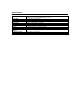
Specifications General Specifications Display Sample Rate Input warning Fuse Protection Power Supply Range selection Over-range Indication Auto Off Low Battery Indication Operating Temperature / Humidity Storage Temperature Dimension / Weight 1999 count 3 1/2 digit, adjustable angle (MV-110, MV-120) 19999 count 4 1/2 digit, adjustable display (MV-130) Approximately 2 - 3 per second Alarm sounds with test leads in the A or 10A socket and the wrong function is selected. 2A (A socket), 0.
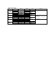
Electrical Specifications Function Range (model) DCV 200mV (MV-110, MV-120) 2, 20, 200V 1000V DCV 200mV (MV-130) 2, 20, 200V 1000V ACV 200mV (MV-110, MV-120) 2, 20, 200V 750V ACV 2, 20, 200V (MV-130) 750V DCA 20µA (MV-110) 200µA, 2, 20 mA 200mA, 2A 10A DCA 20, 200 mA (MV-120) 20A Accuracy % Rdg. + digits ±(0.5% + 1 digit)\ ±(0.8% + 2 digit) ±(0.05% + 3digits) ±(0.1%+ 5 digits) ±(1.2% + 3 digits) ±(0.8% + 3 digits) ±(1.2% + 3 digits) ±(0.8% + 10 digits) ±(1.0% + 15 digits) ±(2.0% + 5 digits) ±(0.
Function DCA (MV-130) ACA (MV-110) Range 2, 20, 200mA 10A 20µA 200µA 2, 20mA 200mA, 2A 10A ACA 20, 200 mA (MV-120) 20A ACA 6 2, 20 200mA (MV-130) 10A Resistance 200Ω (MV-110, MV-120) 2, 20, 200kΩ, 2MΩ 20MΩ 200MΩ Resistance 200Ω (MV-130) 2, 20, 200kΩ, 2MΩ 20MΩ Accuracy % rdg. + digits ±(0.8% + 10 digits) ±(2.0% + 10 digits) ±(3.0% + 7 digits) ±(1.8% + 3 digits) ±(1.0% + 3 digits) ±(1.8% + 3 digits) ±(3.0% + 7 digits) ±(1.0% + 3 digits) ±(3.0% + 7 digits) ±(1.0% + 10 digits) ±(2.0% + 10 digits) ±(0.
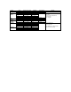
Function Capacitance (MV-120) Capacitance (MV-130) Temperature (MV-120) Frequency (MV-130) Diode test Transistor hFE Continuity Battery check (MV-110) Square Wave (MV-110) Range 2,20,200nF 2,20µF 2,20,200nF 2,20µF -18 to 4000C 0 to7520F -40 to 10000C -40 to 18320F 20kHz 0 to 1000 1.5V 9.0V Accuracy % rdg + digits Resolution ±(2.5% + 3 digits) 1,10,100pF 1nF, 10nF ±(2.5% + 10 digits) 0.1,1,10,100pF 1nF o ±(0.
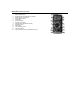
Description (MV120 pictured) 1. 2. 3. 4. 5. 6. 7. 8. 9. 10. 11. 12. 13. Display release button AC/DC selection on models MV110, MV120 Hold Button on model MV130. Power ON/OFF button LCD display Transistor socket Function rotary switch Capacitance socket (MV120, MV130) V/F/Ohms socket COM socket Low Amperage socket 10/20 Amp socket Type K thermocouple input socket (MV120 only).
Operation General Procedures 1. Apply power via ON/OFF switch. If the low battery symbol appears, replace the battery. 2. Set the function switch to the correct position before taking measurements. 3. Press the Display Release Button and set the display to a convenient viewing angle. AC/DC Voltage Measurements (DO NOT EXCEED MAX INPUT LIMIT OF 1000VDC) 1. Connect the black test lead to the meter's COM socket and the red lead to the meter's "VΩF" socket. 2.
Diode Measurements 1. Connect the black test lead to the COM-socket and the red lead to the VΩ socket. 2. Set the rotary switch to the "Diode" symbol position 3. Connect the test leads to the diode under test. 4. The value of the forward voltage drop (0.3 to 0.6V) or the open circuit voltage (2.6V approx.) will appear in the LCD display for a good diode. AC/DC Current Measurements (If the magnitude of current is unknown, select the highest meter range and then reduce the range as needed) 1.
Continuity Measurements (Remove power or voltage from the device under test) 1. Connect the black test lead to the COM-socket and the red lead to the VΩ socket. 2. Set the rotary switch to the "Continuity" symbol position 3. The continuity buzzer will sound if the measured resistance is < 30Ω Battery Measurements (MV-110 only) 1. Connect the black test lead to the COM-socket and the red lead to the VΩ socket. 2. Set the rotary switch to the 1.5V or 9V position 3.
Temperature Measurements (MV-120 only) 1. Insert the type K thermocouple mini-connector into the "K" socket. 2. Set the rotary switch to the ºF or ºC position. 3. The value of the measured temperature will appear in the LCD. Transistor hFe Measurements 1. Move the rotary select switch to the hFe position 2. Plug the transistor under test into the appropriate transistor input jacks on the meter front. 3. For transistor types PNP and NPN, the meter has matching input sockets.