User's Guide Digital Dissolved Oxygen, Conductivity, TDS and pH Meter Model DO700
Introduction Congratulations on your purchase of the Extech DO700 meter. For best results, please read the entire manual before use. The DO700 measures Dissolved Oxygen (DO), Conductivity, pH, mV, and temperature parameters. Conductivity measurements also yield TDS (total dissolved solids), Salinity, and Resistivity readings. The built-in microprocessor provides automatic calibration, automatic temperature compensation, data storage, and self-diagnostics.
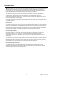
Supplied Equipment List • DO700 Meter • Dissolved Oxygen, Conductivity, and pH Electrode • Standard pH buffer solutions (4.00pH, 7.00pH, and 10.01pH) / 50ml • Standard Conductivity solution (1413µS/cm) / 50ml • Standard Dissolved Oxygen solution (30ml) • Dissolved Oxygen Membrane cap for DO electrode • Cathode polishing paper • Screwdriver (for removing battery compartment cover) • Batteries (2 x ’AA’ 1.5V) • User’s Guide • Carrying Case Meter Description 1.
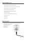
Display Description 1. Measurement type icons 2. Measured reading 3. 888 (Stored data serial number), M+ (measurement to be stored icon), RM (reading to be recalled icon) 4. Units of measure 5. Temperature reading 6. Stable measurement icon 7. Calibration icons 8.
Store, Recall, and Clear Datalogger Memory STORE Readings The meter can store up to 100 DO, 100 pH, 100 mV, and 100 Conductivity readings for a total of 400 data points. To store a reading, wait until the reading stabilizes (the smiling appears when the reading stabilizes). Press the M+/RM key momentarily to face icon store a reading. The M+ icon appears and the data point serial number increments. RECALL Readings In the measurement mode, press the M+/RM key to recall the most recently stored reading.
pH Measurement Mode Preparation for Measurement 1. Unscrew the protective cap on the probe jack located on the bottom of the meter (store the protective cap in the carrying case for later use). 2. Carefully connect the pH probe to the meter’s probe jack. The probe can only be inserted in one orientation. Once it is firmly connected, screw the probe collar onto the meter to secure the probe. . 3. Turn the meter on using the power key 4.
Testing the pH of a Sample 1. Perform the pH Calibratoin as described above 2. Rinse and dry the pH Probe and submerge it in a sample liquid 3. Stir the solution briefly with the probe and allow it to stand until the display stabilizes 4. Note that the closer the temperature of the sample solution to the calibration solution, the more accurate readings Programming pH Parameters The Table below shows the available programming menu items P1 ~ P7.
Parameter P1 (pH Buffer Solution Setting) 1. From the pH measurement mode, press and hold MODE for at least 2 seconds and then release, the ‘P1’ icon appears on the LCD. 2. Use the CAL or the M+/RM keys to toggle through the three (3) selections: USA (for use in the USA or Europe, NIS (for NIST calibration purposes), and CH (for use in China). 3. Momentarily press MODE to move to the next parameter (P2), or press ENTER to return to the normal measurement mode.
pH Measurement, Calibration, and Electrode Considerations • Error messages ERR-1: Electrode zero potential error and ERR-2: Electrode slope error; For either error, check the following: 1. Air bubbles in the electrode bulb. Shake rigorously to remove air bubbles 2. Accuracy of the pH buffers used in calibration. Replace buffers if necessary 3.
mV Measurement Mode 1. Unscrew the protective cap on the probe jack located on the bottom of the meter (store the protective cap in the carrying case for later use). 2. Carefully connect the pH probe to the meter’s probe jack. The probe can only be inserted in one orientation. Once it is firmly connected, screw the probe collar onto the meter to secure the probe. . 3. Turn the meter on using the power key 4. Press the MODE key momentarily to switch to the mV mode. 5.
Conductivity Measurement Mode Preparation for Measurement 1. Unscrew the protective cap on the probe jack located on the bottom of the meter (store the protective cap in the carrying case for later use). 2. Carefully connect the electrode to the meter’s input jack. The electrode can only be inserted in one orientation. Once it is firmly connected, screw the electrode collar onto the meter to secure it. . 3. Turn the meter on using the power key 4.
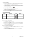
Measuring range 0.05 to 20μS/cm Electrode constant K=0.1cm Calibration solution 84μS/cm -1 0.5μS/cm to 200mS/cm (flow test) K=1.0cm 84μS/cm -1 1413μS/cm 12.88 mS/cm 111.9 mS/cm Calibration indicator L L M H There are two electrode calibration methods: Standard Solution calibration and Constant calibration.
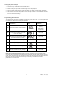
Programming Parameters - Conductivity The Table below shows the available programming menu items P1 ~ P9. Each parameter is explained in detail in the subsequent sections. Parameters Code Selections P1 Standard solution series selection sol USA (Europe & U.S.A) CH (China) P2 Electrode Constant selection 0.1, 1, or 10 P3 Reference Temperature selection 77, 68, and 64 F (25, 20,and 18 ℃) P4 Temperature compensation coefficient setting 0.00 to 9.
Parameter P3 (Reference Temperature Selection) 1. From the P3 menu, use the CAL or the M+/RM keys to select the desired reference temperature (25, 20, or 18℃).The default setting is 25℃ 2. Momentarily press MODE to move to the next parameter (P4) or press ENTER to return to the normal measurement mode Parameter P4 (Temperature Coefficient Temperature Compensation Setting) 1. From the P4 menu, use the CAL or the M+/RM keys to select the coefficient in percent from 0.00 to 9.99.
Conductivity Measurement, Calibration, and Maintenance Considerations • The meter and probe are calibrated before leaving the factory; the user can take measurements immediately upon receiving the unit. • The recommend calibration period is once per month under normal circumstances; It is necessary to calibrate a newly purchased conductivity electrode or one that has been in service for a long period of time. • Keep the conductivity electrode clean.
Dissolved Oxygen (DO) Measurements Preparation • Remove the DO electrode from the solution bottle. • Determine if the sponge inside the bottle is moist. If not, moisten the sponge but do not allow excess water in the bottle. • Small air bubbles are acceptable in the electrode but larger air bubbles should be removed. To do so, remove the membrane cap and add electrolyte. Connect the electrode to the meter and allow for a 15-minute polarization.
Dissolved Oxygen Water Sample Test • To measure moving water (water sample velocity of flow >5cm/s) insert the DO electrode into the water. The water surface should cover the electrode’s thermistor (temperature sensor). The recommended electrode orientation with regard to the water is a 45°to 75°angle. Move the electrode around in the water and allow 3 to 5 minutes to take the reading.
Parameter Settings Prompt Parameters Code Selections P1 Resolution selection 0.01/0.1(mg/L and ppm) 0.1/1(%) P2 Salinity calibration P3 Barometric pressure setting P4 Temperature unit setting P5 Back light display time setting 0-1-3-6 min P6 Auto power off time setting 0-10-20 min P7 Restore to producer setting OFF-On (shut-set) Refer to explanation below 66 to 200kPa o o C/ F P1 - Resolution selection • Press the MODE key to enter the P1 parameter mode.
P4 - Temperature unit of measure selection o o • Use the CAL or the M+/RM keys to select the desired unit of measure ( C or F). • Momentarily press MODE to move to the next parameter or press ENTER to return to the normal measurement mode. P5 - Display Backlight Setting • Use the CAL or the M+/RM keys to select 0, 1, 3, or 6 minute default backlighting time. • Momentarily press MODE to move to the next parameter or press ENTER to return to the normal measurement mode.
Zero Dissolved Oxygen Calibration The meter receives a zero oxygen calibration before leaving the factory and only requires a zero oxygen calibration when the electrode (or the electrode cap) is replaced or has been in use for a relatively extended period of time (6 months or longer). To perform a zero oxygen calibration: 1. Prepare 100mL of anaerobic water: In a 100 mL beaker add 5g anhydrous sodium sulfite (Na2SO3) to 100 mL distilled water. Stir to dissolve.
Specifications pH Specifications Measuring range Resolution Accuracy Input current Input impedance Stability Temp. Compensation range -2.00 to 19.99 pH 0.1/0.01 pH Meter only: ±0.01pH; with probe: ±0.02pH -12 ≤2×10 A 12 ≥1×10 Ω ±0.01 pH/3h o o 32 to 212 F (0 to 100 C); Automatic (ATC) mV Specifications Measuring range (mV/EH) Resolution Accuracy -1999 mV to 0 to 1999mV 1mV Meter: ±0.
Appendices Appendix A - Abbreviation Glossary Code or Abbreviation Translation Description Solution Standard solution Chinese Chinese series standard USA Europe / USA series standard NIST NIST series standard Pure1 pH Temperature compensation setting for Distilled Water Pure2 pH Temperature compensation setting for Distilled Water with Ammonia Constant Electrode constant setting Temperature Compensation Coefficient Setting for temperature compensation coefficient Reference Temperature Re
Appendix B – DO of Saturated Water vs. Temperature Temperature ℃ DO mg/L @ 1 atm Temperature ℃ DO mg/L @ 1 atm Temperature ℃ DO mg/L @ 1 atm 0 14.64 16 9.86 32 7.30 1 14.22 17 9.66 33 7.18 2 13.82 18 9.46 34 7.07 3 13.44 19 9.27 35 6.95 4 13.09 20 9.08 36 6.84 5 12.74 21 8.90 37 6.73 6 12.42 22 8.73 38 6.63 7 12.11 23 8.57 39 6.53 8 11.81 24 8.41 40 6.43 9 11.53 25 8.25 41 6.34 10 11.26 26 8.11 42 6.25 11 11.01 27 7.96 43 6.
Appendix C - DO of Saturated Water vs Barometric Pressure and Temperature Barometric pressure Dissolved Oxygen Concentration (mg/L) o o o mmHg kPa 15 C 25 C 35 C 750 100.00 9.94 8.14 6.85 751 100.13 9.96 8.15 6.86 752 100.26 9.97 8.16 6.87 753 100.40 9.98 8.17 6.88 754 100.53 9.99 8.18 6.89 755 100.66 10.00 8.20 6.90 756 100.80 10.01 8.21 6.91 757 100.93 10.03 8.22 6.92 758 101.06 10.04 8.23 6.93 759 101.20 10.07 8.24 6.94 760 101.33 10.08 8.
Appendix D – DO of Saturated Water vs. Altitude Altitude Feet Barometric pressure meters kPa mmHg DO (25°C) Altitude mg/l Feet Meters Barometric pressure kPa mmHg DO (25°C) mg/l 0 0 101.3 760 8.25 7500 2287 77.1 579 6.28 500 152 99.34 746 8.09 8000 2439 75.63 568 6.16 1000 305 97.6 733 7.95 8500 2591 74.44 559 6.06 1500 457 95.87 720 7.81 9000 2744 72.97 548 5.94 2000 610 94.28 708 7.68 9500 2896 71.64 538 5.83 2500 762 92.54 695 7.
Warranty EXTECH INSTRUMENTS CORPORATION (A FLIR COMPANY) warrants this instrument to be free of defects in parts and workmanship for one year from date of shipment (a six month limited warranty applies to sensors and cables). If it should become necessary to return the instrument for service during or beyond the warranty period, contact the Customer Service Department at (781) 890-7440 ext. 210 for authorization or visit our website www.extech.com for contact information.