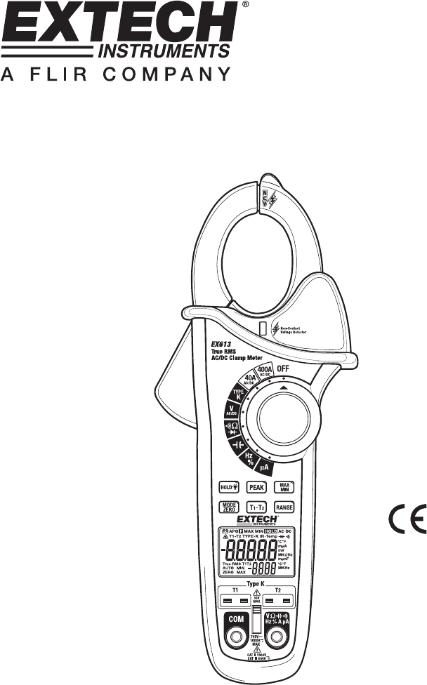
User's Guide 400Amp True RMS AC/DC Clamp Meter Model EX613
Introduction Congratulations on your purchase of this Extech EX613 True RMS Clamp Meter. This meter measures AC Current, DC Current, AC/DC Voltage, Resistance, Capacitance, Frequency, Diode Test, Duty Cycle and Continuity. Special features include Dual Input Thermocouple Temperature, and NonContact Voltage detector. The double molded case is designed for heavy duty use. This meter is shipped fully tested and calibrated and, with proper use, will provide years of reliable service.
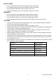
SAFETY NOTES • • • • Do not exceed the maximum allowable input range of any function. Do not apply voltage to meter when resistance function is selected. Set the function switch OFF when the meter is not in use. Remove the battery if meter is to be stored for longer than 60 days. WARNINGS • • • • Set function switch to the appropriate position before measuring. When measuring volts do not switch to current/resistance modes. Do not measure current on a circuit whose voltage exceeds 600V.
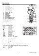
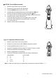
Description Meter Description 1. 2. 3. 4. 5. 6. 7. 8. 9. 10. 11. 12. 13. 14. 15. 16.
Operation NOTES: Read and understand all Warning and Caution statements in this operation manual prior to using this meter. Set the function select switch to the OFF position when the meter is not in use. Input Shutter The Input Shutter inhibits simultaneous connection to the thermocouple jacks and the DMM input jacks. This is a safety feature which prevents a potentially hazardous condition from existing during high voltage measurements.
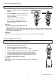
AC/DC Current Measurements WARNING: Disconnect the test leads before making clamp measurements. 1. Rotate the Function switch to the 400AAC/DC position 2. Press the MODE button to select AC or DC. 3. Press the trigger to open jaw. Fully enclose only one conductor. 4. Read the current value in the display. 5. If the value is less than 40A, rotate the function switch to the 40AAC/DC position to improve resolution.
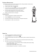
Resistance Measurements Note: Remove power from the device under test before making resistance measurements 1. Slide the input shutter to the up position. 2. Set the function switch to the Ω position. 3. Insert the black test lead banana plug into the negative COM jack. Insert the red test lead banana plug into the positive V jack. 4. Touch the black test probe tip to one side of the device. Touch the red test probe tip to the other side of the device. 5. Read the resistance value in the display.
Capacitance Measurements WARNING: To avoid electric shock, discharge the capacitor before measuring. 1. Slide the input shutter to the up position. 2. Rotate the function switch to the 3. Insert the black test lead banana plug into the negative COM jack. jack. Insert the red test lead banana plug into the positive 4. Touch the black test probe tip to one side of the device. Touch the red test probe tip to the other side of the device. 5. Read the capacitance value in the display.
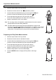
μA DC/AC Current Measurements 1. Slide the input shutter to the up position. 2. Rotate the function switch to the μA position. 3. Press the MODE button to select AC or DC. 4. Insert the black test lead banana plug into the negative COM jack. Insert the red test lead banana plug into the positive μA jack. Turn power to the circuit under test off and make a break in the circuit. Insert the meter in series with the circuit; Touch the black test probe tip to the negative side of the break.
Data Hold To freeze the LCD reading, press the HOLD button. While data hold is active, the HOLD icon appears on the LCD. Press the HOLD button again to return to normal operation. MAX/MIN 1. 2. 3. 4. Press the MAX/MIN button to activate the MAX/MIN recording mode. The display icon "MAX" will appear. The meter will begins recording and displaying the maximum value measured. Press the MAX/MIN button and “MIN” will appear. The meter will display the minimum value measured during the recording session.
Maintenance WARNING: To avoid electrical shock, disconnect the meter from any circuit, remove the test leads from the input terminals, and turn OFF the meter before opening the case. Do not operate the meter with an open case. Cleaning and Storage Periodically wipe the case with a damp cloth and mild detergent; do not use abrasives or solvents. If the meter is not to be used for 60 days or more, remove the battery and store it separately. Battery Replacement 1.
Specifications Range AC Current 400.0 AAC 0.1A 50/60 Hz True RMS 40.00 AAC 0.01A DC Current 400.0 ADC 0.1A 40.00 ADC 0.01A 400.00μA 0.01μA DC: ±(1.0% + 2 digits) 4000.0μA 0.1μA AC: ±(1.5% + 2 digits) ±(1.0% + 20 digits) AC/DC μA Current Resolution Accuracy (% of reading + digits) Function AC Voltage 400.0 mVAC 0.1mV 50/60 Hz True RMS 4.000 VAC 0.001V 40.00 VAC 0.01V 400.0 VAC 0.1V 600 VAC DC Voltage Resistance Capacitance Frequency (clamp) ±(1.5% + 5 digits) ±(1.
Function Range Resolution Frequency (test leads) 40.000Hz 0.001Hz 400.00Hz 0.01Hz 4000.0Hz 0.1Hz 40.000kHz 0.001kHz 400.00kHz 0.01kHz 4000.0kHz 0.1kHz 40.000MHz 0.001MHz 100.00MHz 0.01MHz Accuracy (% of reading + digits) ±(0.3% + 3 digits) ±(0.3% + 2 digits) Not specified Sensitivity: 5 to 5kHz; 0.8Vrms min., 5kHz to 150kHz; 5Vrms min Duty Cycle 0.5% to 99.0% 0.1% ±(1.2% + 2 digits) Temperature Type K -58 to -4°F -50 to -19°C ±13°F/7°C -4 to 31°F -20 to -1°C ±(1.
General Specifications Clamp jaw opening Display Non-Contact Voltage Continuity check Diode test Low Battery indication Over-range indication Measurement rate Peak detector Thermocouple sensor Fuse Input Impedance AC bandwidth AC response Crest Factor Operating Temperature Storage Temperature Operating Humidity Storage Humidity Operating Altitude Battery Auto power OFF Dimensions & Weight Safety Approvals 32mm (1.25") approx.