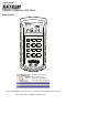
User's Guide Passive Component LCR Meter Model 380193 LCR M eter 3 8 01 9 3 APO AUTO D PAL c 1kHz µ -0 ENTER L/C/R Q/D/R 2 3 L/C/R Q/D/R 5 6 MIN MAX SET 7 8 9 REL Hi / Lo LIMITS TOL 1 RANGE 4 >2sec HOLD F DO NOT APPLY VOLTAGE TO TERMINALS DISCHARGE CAPACITOR BEFORE TESTING + AUTO-POWER OFF 99 Washington Street Melrose, MA 02176 Phone 781-665-1400 Toll Free 1-800-517-8431 Visit us at www.TestEquipmentDepot.com Back to the Extech 381193 Product Page Test Equipment Depot - 800.
INTRODUCTION Congratulations on your purchase of Extech's Model 380193 LCR meter. This meter will accurately measure capacitors, inductors and resistors using the test frequencies of 120Hz and 1 kHz. The dual display will simultaneously display the associated quality factor, dissipation or resistance value using a series or parallel equivalent circuit.
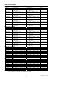
SPECIFICATIONS Capacitance @ 120Hz Range Cx accuracy DF accuracy Note 9.999mF ±(5.0% rdg + 5d) ±(10%rdg + 100/Cx + 5d) after short cal (DF<0.1) (DF<0.1) 1999.9µF ±(1.0% rdg + 5d) ±(2%rdg + 100/Cx + 5d) after short cal (DF<0.1) (DF<0.1) 199.99µF ±(0.7% rdg + 3d) ±(0.7%rdg + 100/Cx + 5d) (DF<0.5) (DF<0.1) 19.999µF ±(0.7% rdg + 3d) ±(0.7%rdg + 100/Cx + 5d) (DF<0.5) (DF<0.1) 1999.9nF ±(0.7% rdg + 3d) ±(0.7%rdg + 100/Cx + 5d) (DF<0.5) (DF<0.1) 199.99nF ±(0.7% rdg + 5d) ±(0.
Resistance Range accuracy (1kHz & 120Hz) Note ±(2.0%rdg + 8d) after open cal* 10.000MΩ ±(0.5%rdg + 5d) after open cal* 1.9999MΩ ±(0.5%rdg + 3d) 199.99kΩ ±(0.5%rdg + 3d) 19.999kΩ ±(0.5%rdg + 3d) 1.9999kΩ ±(0.8%rdg + 5d) after short cal 199.99Ω ±(1.2%rdg + 8d) after short cal 0.020 to 19.999Ω *Note: For resistance readings above 1MΩ, series and parallel impedances may affect readings (especially at 1kHz).
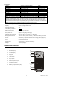
Display Symbols and Annunciators APO Auto Power Off 1KHz 1kHz test frequency R Recording mode active 120Hz 120Hz test frequency MAX Maximum reading M Mega (10 ) MIN Minimum reading K kilo (10 ) AVG Average reading p pico (10 ) AUTO AutoRanging active n nano (10 ) H Data hold active µ micro (10 ) SET SET mode m milli (10 ) TOL Tolerance mode H Henry (inductance units) PAL Parallel equivalent circuit F Farad (capacitance units SER Series equivalent circuit Ω Ohms (re
OPERATING INSTRUCTIONS CAUTION: Measuring a DUT (device under test) in a live circuit will produce false readings and may damage the meter. Always remove power and isolate the component from the circuit to obtain an accurate reading. CAUTION: Do not apply voltage to the input terminals. Discharge capacitors before testing Note: Measurement considerations for resistance <0.5 ohms. 1. Use positive contact alligator clips. 2. Perform a SHORT calibration zero to remove stray impedances. 3.
Inductance, Capacitance, Resistance Selection The L/C/R key selects the primary parameter measurement function. Each press of the key will select either inductance (L), capacitance (C) or resistance (R) along with the proper units of H (henries), F (farads) or Ω (ohms) in the main large display. Quality, Dissipation, Resistance Selection The Q/D/R key selects the secondary parameter measurement function.
Hi / Lo Limits Mode The Hi / Lo limits mode compares the measured value to the stored high and low limit values and gives an audible and visible indication if the measured value is outside the limits. See the setting Hi/Lo limits paragraph below to store the limits in memory. 1. Press the Hi/Lo LIMITS key to enter the mode. The display will briefly show the stored upper limit with the “ “ indicator and then the stored lower limit with the “ “ indicator before displaying the measured value. 2.
Setting Absolute Hi/Lo Limits The Hi/Lo limits set allows the user to enter an upper and lower limit value into memory for comparison to the measured value. 1. Press the SET key and then the Hi / Lo LIMITS key. The upper limit “ “ indicator will flash and the previously stored upper limit will appear with the first digit flashing. 2. Set the value of the flashing digit by pressing the appropriate numeric key. The adjustment selection will then proceed through each digit from left to right. 3.