User's Guide Mini Multimeter with Non-Contact Voltage Detector (NCV) Model EX320
Introduction Congratulations on your purchase of the Extech EX320 Meter. The EX320 offers AC/DC Voltage, AC/DC Current, Resistance, Diode, Continuity, non-contact Voltage Detection. Proper use and care of this meter will provide many years of reliable service. Safety This symbol adjacent to another symbol, terminal or operating device indicates that the operator must refer to an explanation in the Operating Instructions to avoid personal injury or damage to the meter.
CAUTIONS • Improper use of this meter can cause damage, shock, injury or death. Read and understand this user manual before operating the meter. • Always remove the test leads before replacing the battery or fuses. • Inspect the condition of the test leads and the meter itself for any damage before operating the meter. • Use great care when making measurements if the voltages are greater than 25VAC rms or 35VDC. These voltages are considered a shock hazard. • Warning! This is a class A equipment.
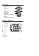
Controls and Jacks 1. 1 2 AC Voltage Detector Sensor 2. AC Voltage Detector indicator light 3. LCD 4. MAX push-button 5. MODE button 6. Non-contact AC Voltage Detector test button 7. Rotary function dial 8. 10 ampere test lead jack 9. COM test lead jack 3 13 4 5 6 12 11 7 10. Test lead jack for voltage, milli-amp, microamp, resistance 11. RANGE button 10 8 12. HOLD button 13.
Operating Instructions WARNING: Risk of electrocution. High-voltage circuits, both AC and DC, are very dangerous and should be measured with great care. 1. ALWAYS turn the function switch to the OFF position when the meter is not in use. 2. Press the HOLD button to freeze a displayed reading NOTE: On some low AC and DC voltage ranges, with the test leads not connected to a device, the display may show a random, changing reading. This is normal and is caused by the high-input sensitivity.
AC VOLTAGE MEASUREMENTS WARNING: Risk of Electrocution. The probe tips may not be long enough to contact the live parts inside some 240V outlets for appliances because the contacts are recessed deep in the outlets. As a result, the reading may show 0 volts when the outlet actually has voltage on it. Make sure the probe tips are touching the metal contacts inside the outlet before assuming that no voltage is present. CAUTION: Do not measure AC voltages if a motor on the circuit is being switched ON or OFF.
AC / DC CURRENT MEASUREMENTS CAUTION: Do not make current measurements at 10 Amps for longer than 30 seconds. Exceeding 30 seconds may cause damage to the meter and/or the test leads. 1. 2. 3. 4. 5. 6. 7. 8. 9. Insert the black test lead banana plug into the negative COM jack.
RESISTANCE MEASUREMENTS WARNING: To avoid electric shock, disconnect power to the unit under test and discharge all capacitors before taking any resistance measurements. Remove the batteries and unplug the line cords. 1. 2. 3. 4. Set the function switch to the Ω position. Insert the black test lead banana plug into the negative COM jack. Insert the red test lead banana plug into the positive Ω jack. Touch the test probe tips across the circuit or component under test.
DIODE TEST 1. 2. 3. 4. Set the function switch to the position. Insert the black test lead banana plug into the negative COM jack and the red test lead banana plug into the positive jack. Use the MODE button to view the icon on the display. Touch the test probes to the diode under test. Forward voltage will typically indicate 0.400 to 0.700V. Reverse voltage will indicate “OL”. Shorted devices will indicate near 0V and an open device will indicate “OL” in both polarities.
Maintenance WARNING: To avoid electric shock, disconnect the test leads from any source of voltage before removing the back cover or the battery or fuse covers. WARNING: To avoid electric shock, do not operate your meter until the battery and fuse covers are in place and fastened securely. This MultiMeter is designed to provide years of dependable service, if the following care instructions are performed: 1. KEEP THE METER DRY. If it gets wet, dry it immediately. 2.
BATTERY INSTALLATION and LOW BATTERY INDICATION WARNING: To avoid electric shock, disconnect the test leads from any source of voltage before removing the battery cover. LOW BATTERY INDICATION The icon will appear in the lower left-hand corner of the display when the battery voltage becomes low. Replace the batteries when this appears. BATTERY REPLACEMENT 1. Disconnect the test leads from the meter. 2. Remove the protective rubber holster as shown in the diagram. 3.
1. Removable Rubber Holster 2. Meter 3. Battery 4. Fuses 5. Compartment Cover 6. Rubber Holster REPLACING THE FUSES WARNING: To avoid electric shock, disconnect the test leads from any source of voltage before removing the fuse cover. 1. Disconnect the test leads from the meter. 2. Remove the protective rubber holster as shown in the diagram. 3. Remove the Phillips head screw located on the lower back of the instrument. 4. Flip up the fuse/battery compartment cover to access the fuses.
Specifications Function Range Non-contact AC 100 to Voltage detector 600VAC Resolution Accuracy Resolution & accuracy do not apply since the meter does not display the voltage in this mode. The lamp at the top of the meter’s display flashes when voltage is sensed and an audible warning will sound DC Voltage 200mV 0.1mV (V DC) 2V 0.001V ±(0.5% reading + 2 digits) ±(1.0% reading + 2 digits) 20V 0.01V 200V 0.1V 600V 1V ±(1.5% reading + 2 digits) ±(1.
General Specifications Test current: 0.3mA max., Open circuit voltage: 1.5V DC typ. Audible signal will sound if the resistance is less than 100Ω 10MΩ (VDC & VAC) 50 / 60Hz 2000 count (0 to 1999 digits) backlit LCD For all functions “OL” is displayed After 15 minutes (approximately) of inactivity No indication for positive; Minus (-) sign for negative 2 times per second, nominal “ ” is displayed if battery voltage is critically low Two (2) 1.