USER MANUAL True RMS Digital Multimeters EX360 Series EX360 True RMS Digital Multimeter EX363 True RMS DMM with Temperature and µA AC/DC EX365 True RMS DMM with 10A AC/DC Current Additional User Manual Translations available at www.extech.
Table of Contents 1. INTRODUCTION 3 2. SAFETY INFORMATION 4 3. DESCRIPTIONS 6 4.
1. Introduction Thank you for selecting the Extech EX360 Series Meter. The EX360 Series are feature‐packed True RMS digital multimeters. In addition to standard DMM features, they offer a Low Impedance (Lo Z) mode, Smart Data Hold, Automatic AC/DC voltage Detect mode, Backlit LCD, and a Non‐Contact Voltage Detector that senses electrical sources safely. This device is shipped fully tested and calibrated and, with proper use, will provide years of reliable service. Please visit our website (www.extech.
2. Safety Information To ensure the safe operation and service of the meter, follow these instructions closely. Failure to observe warnings can result in severe injury. WARNINGS WARNINGS identify hazardous conditions and actions that could cause BODILY HARM or DEATH. When handling test leads or probes, keep hands and fingers behind the finger guards at all times. Remove test leads from the meter before opening the battery compartment or meter housing.
Safety Symbols that are typically marked on meters and instructions This symbol, adjacent to another symbol, indicates the user must refer to the manual or user guide for further information. Risk of electrical shock Fuse symbol Equipment protected by double or reinforced insulation Battery symbol Conforms to EU directives Do not discard this product in household trash.
3. Descriptions Meter Description (EX365 pictured) 1. Non‐Contact Voltage Detector and Continuity alert light 2. LCD multi‐function display 3. M (MODE) button (also oC/oF button on EX363) 4. R RANGE and Lo/Hi button 5. Rotary function select switch 6. Positive input terminal (10A Current) for EX365 only 7. Common (‐) input terminal 8. Positive input terminal: Voltage, Resistance, Capacitance, Temperature (EX363), and µA (EX363) 9. LCD Backlight button 10. H Data Hold button 11.
Display Icon Descriptions HOLD: Display hold Lo Z: Low Impedance mode : Relative mode and AC: Alternating Current Measurements and DC: Direct Current Measurements : Main display digits : Bar graph A: Amperes (Current) V: Volts (Voltage) oC/oF: Temperature units F: Farads (Capacitance measurement units) Hz: Hertz (Frequency measurements unit) Ω (Ohms): Resistance measurement unit :Battery status icon ‐ Minus (negative) sign : Non‐Contact Volt Detect and high v
Push‐Button Descriptions Press the M (MODE) button to perform the following. The oC/oF function is only available on the EX363 model: Switch Position MODE (M) Button Function (EX365) V Hz A Hz Ω Ω µA (EX363) AC DC o o TEMP (EX363) C F Press R (Range) to switch from Auto to Manual Range. Hold to return to Auto Range. Press to select Non-Contact Voltage Detector Sensitivity Lo (low) or Hi (high). Short press activates Relative mode; long press access/exit PEAK MAX-MIN mode.
4. Operation CAUTION: Read and understand all of the Safety statements listed in the safety section of this manual prior to use. Powering the Meter 1. Turn the rotary function switch to any position to power the meter. Check the batteries if the unit fails to power ON. Refer to the Maintenance section for battery and fuse replacements. 2. Turn the function switch to the OFF position to power OFF the meter. 3.
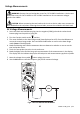
Voltage Measurements WARNING: Remove the test lead probe covers for CAT II 1000V installations. Use the test lead probe covers for CAT III 1000V or CAT IV 600V installations. Do not measure voltages greater than 1000V. CAUTION: When connecting the test leads to the circuit or device under test, connect the black lead before the red; when removing the test leads, remove the red before the black lead. AC Voltage Measurements 1.
DC Voltage Measurements 1. Insert the black test lead banana plug into the negative (COM) jack and the red test lead banana plug into the positive (V/Ω) jack. 2. Move the Function Switch to the 3. Read the Warning and Caution statements at the beginning of this section to determine whether or not to use the test lead probe covers. 4. Touch the test probe tips to the circuit under test. Be sure to observe the correct polarity (red lead to positive, black lead to negative). 5.
Lo Z Voltage Measurements When the function switch is turned to the Lo Z position, the meter incorporates an automatic voltage detection circuit to automatically determine voltage AC or DC and a low Z (impedance) circuit* that eliminates ghost voltage complications. Refer to the Voltage Measurements section earlier in this guide for Safety information and connection diagrams. *The Lo Z impedance is approx. 3kΩ increasing to over 100kΩ when measuring 1000V. 1.
10A AC/DC Current Measurements (EX365 only) WARNING: Do not handle the test leads above the finger/hand guard barrier. CAUTION: Observe CAT III 1000V CAT IV 600V with respect to Earth Ground. 1. Insert the black test lead into the COM terminal and the red test lead into the A terminal. 2. Turn the meter’s function switch to the display indicating Amperes (Amps). 3. The meter defaults to the Auto Range mode. When in Auto mode, the display shows the Auto icon in the upper left corner.
µA AC/DC Current Measurements (EX363 only) WARNING: Do not handle the test leads above the finger/hand guard barrier. CAUTION: Observe CAT III 1000V and CAT IV 600V with respect to Earth Ground. 1. Insert the black test lead into the COM terminal and the red test lead into the µA terminal. 2. Turn the meter’s function switch to the µA position. The µA units symbol will appear on the display indicating that micro‐amperes are being measured. 3. The meter defaults to the Manual Range mode.
Non‐Contact Voltage Detector WARNING: It is possible for voltage to be present in a circuit even if the meter does not beep or light the NCV LED lamp at the top of the meter. Always verify meter operation on a known live AC current circuit and verify that the batteries are fresh before use. The audible beeper sounds and the LED lamp at the top of the meter lights when the meter senses an electrical voltage field.
Resistance Measurements Cautions: Switch OFF power to the device under test before measuring. Do not test on circuits or devices where 60VDC or 30VAC is present. 1. 2. 3. 4. 5. Insert the black test lead banana plug into the negative (COM) jack. Insert the red test lead banana plug into the positive (V/Ω) jack. Turn the Function Switch to the Ω position. Use the M button to select the Ω icon on the display indicating resistance only (without the audible continuity icon showing).
Capacitance Measurements WARNING: To avoid electric shock, remove power to the circuit under test and discharge the capacitor under test before measuring. Do not test on circuits or devices where 60VDC or 30VAC is present. 1. Set the function switch to the 2. Insert the black test lead banana plug into the negative COM jack and the red test lead banana plug into the positive jack. 3. 4. 5. Press the M button to select the unit of measure symbol F. Touch the test probe tips across the part under test.
Diode Test 1. Insert the black test lead banana plug into the negative COM jack and the red test lead banana plug into the positive jack. 2. Turn the function switch to position. Use the M button to select the diode function if necessary (the diode and voltage symbols will appear on the LCD when in Diode test mode). 3. Touch the test probe tips to the diode or semiconductor junction under test. Note the meter reading. 4. Reverse the test lead polarity by reversing the red and black leads.
Temperature Measurements (EX363 only) 1. Insert the supplied temperature probed into the COM and positive terminals observing correct polarity. 2. Turn the function switch to the temperature position. Use the oC/oF button to select the desired unit of measure. 3. Touch the temperature probe tip to the device under test or leave the temperature probe in the open air to measure ambient temperature. 4. Read the temperature measurement on the LCD. 5.
5. Maintenance WARNING: To avoid electrical shock, remove the test leads, disconnect the meter from any circuit and turn OFF the meter before opening the case. Do not operate with an open case. Battery Replacement 1. Remove the test leads from the meter. 2. Remove the meter’s protective cover. 3. Remove the two Phillips head screws that secure the battery compartment at the back of the meter. 4. Open the battery compartment and replace the 9V battery observing correct polarity.
Fuse Replacement WARNING: To avoid electrical shock, remove the test leads, disconnect the meter from any circuit and turn OFF the meter before opening the case. Do not operate with an open case. Follow the steps in the accompanying 11A/1000V (10x38mm) fuse replacement diagram. 1. Remove the test leads from the meter. 2. Remove the meter’s protective cover. 3. Remove the four (4) screws that secure the meter housing. 4. Replace the fuse with one of the same type and rating.
6. Specifications ELECTRICAL SPECIFICATIONS Accuracy is given as ± (% of reading + least significant digit) at 23C ±5C with relative humidity lower than 80%. Accuracy is specified for a period of one year after calibration. 1. Temperature Coefficient is 0.1 x specified accuracy / C, < 18C (64.5F), > 28C (82.4F) 2. AC Functionality: ACV and ACA specifications are AC coupled, True RMS; the accuracy for square waveforms is unspecified. For non‐sinusoidal waveforms, additional accuracy Crest Factor (C.F.
Function µA AC (EX363 only) Range 600.0 µA Resolution Accuracy (of reading) 0.1uA ‘OL’ Reading ± (1.5% + 3 digits) 660.0µA LCD Displays ‘0’ counts when the reading < 10 counts Input Impedance: 3kΩ approx. Frequency Response: 45~500Hz (sine wave) Over load protection: 1000V AC/DC AC Current (EX365) 6.000 A 0.001 6.600A ± (1.5% + 3 digits) 10.00 A 0.01 20.00A In 6A Range, the LCD displays 0 counts when the reading < 20 counts. In10A Range, the LCD displays 0 counts when the reading < 10 counts.
Function Frequency Range Resolution Accuracy (of reading) 100.00 Hz 0.01 Hz 1000.0 Hz 0.1 Hz ‘OL’ Reading 100.00 Hz 1000.0 Hz ± (0.1% + 2 digits) 10.000 kHz 0.001kHz 10.000 kHz 100.00 kHz 0.01kHz 100.00 kHz Minimum Sensitivity: > 5V (for ACV 1Hz ~ 10kHz) > 20.0V (for ACV 10kHz ~ 50kHz) unspecified (for ACV 50kHz ~ 100kHz) >0.6A (for ACA) Minimum Frequency: 1Hz Overload Protection: AC/DC 1000V or 11A Temp. (EX363) ‐40.0~400.0 oC 0.1o ± (1.0% + 20 digits)* 440.0 oC ‐40.0~752.0 oF 0.
GENERAL SPECIFICATIONS Display Over‐range indication Conversion rate Maximum Voltage Polarity indication 6000‐count Multi‐Function LCD “OL” or “‐OL” is displayed 3 updates per second 1000VAC RMS or 1000V DC maximum applied to any terminal Automatic: positive implied, negative indicated (‐) Low battery indication is displayed.