USER GUIDE 600A True RMS Digital Clamp Meters EX650 Series EX650 True RMS 600A AC Digital Clamp Meter EX655 True RMS 600A AC/DC Clamp Meter with Temperature, Inrush, and Low Pass Filter
Table of Contents 1. INTRODUCTION 3 2. SAFETY INFORMATION 4 3. DESCRIPTIONS 6 4. OPERATION 11 5. MAINTENANCE 31 6. SPECIFICATIONS 32 7.
1. Introduction Thank you for selecting the Extech EX650 Series Clamp Meter. The EX650 is a feature‐packed True RMS digital Clamp meter series with 6000 count backlit display and automatic ranging. Measure AC/DC voltage, AC current, DC current (EX655), Inrush current (EX655), Resistance, Diode, Continuity, Capacitance, Temperature (EX655), Lo ‘Z’ low impedance mode, and Frequency (EX655).
2. Safety Information To ensure the safe operation and service of the meter, follow these instructions closely. Failure to observe warnings can result in severe injury. WARNINGS WARNINGS identify hazardous conditions and actions that could cause BODILY HARM or DEATH. When handling test leads or probes, keep hands and fingers behind the finger guards at all times. To avoid electrical shock do not touch exposed electrical wire, connectors, unused input terminals, or circuits under test.
Safety Symbols that are typically marked on meters and instructions This symbol, adjacent to another symbol, indicates the user must refer to the manual or user guide for further information. Risk of electrical shock Fuse symbol Equipment protected by double or reinforced insulation Low Battery symbol Conforms to EU directives Do not discard this product in household trash.
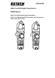
3. Descriptions Meter Description (EX655 pictured) 1. Non‐Contact Voltage Detector 2. Clamp jaw 3. Work Light ON/OFF button 4. NCV alert LED lamp 5. Rotary function switch 6. Max‐Min button 7. Relative 8. LCD multi‐function display with backlighting 9. Positive input terminal 10. Common (‐) input terminal 11. Mode (M) and LPF (low pass filter) button (LPF on EX655 only) 12. Backlight and Hold button 13. Jaw Trigger 14.
Display Icon Descriptions for EX650 1 234 5 6 7 8 9 10 11 12 13 14 15 16 Fig 3‐2 EX650 METER DISPLAY 1. High voltage 2. Battery status 3. Relative mode 4. Auto power off 5. Data hold 6. Units of measure 7. Direct Current 8. Alternating Current 9. Diode 10. Continuity 11. Automatic range 12. Low Impedance mode (Lo Z) 13. Maximum and Minimum memory 14. Non‐Contact Voltage Detector 15. Low Pass Filter (LPF) 16. Temperature units 7 EX65x‐en‐US_V1.
Display Icon Descriptions for EX655 1 2 3 4 5 6 7 8 9 10 18 11 12 13 14 15 16 17 Fig 3‐3 EX655 METER DISPLAY 1. High voltage 2. Battery status 3. Relative mode 4. Auto power off 5. Data hold 6. Units of measure 7. Direct Current 8. Alternating Current 9. Diode 10. Continuity 11. Automatic range 12. Low Impedance mode (Lo Z) 13. Inrush Current (Surge) 14. Maximum and Minimum memory 15. Non‐Contact Voltage Detector 16. Low Pass Filter (LPF) 17. Temperature units 18.
Push‐Button Descriptions Momentary presses of the M (MODE) button perform the functions shown in the table below. Press and hold the button to activate/deactivate the Low Pass Filter (EX655 only). Fig. 3‐4 (a) EX655 MODE Button Function Table Switch Position MODE (M) Button Function AC Hz AC DC DC or Ω o TEMP C o F Fig. 3‐4 (b) EX650 MODE Button Function Table Switch Position MODE (M) Button Function AC DC AC DC Ω Momentarily press to access/exit the Relative mode.
Fig 3‐5(a) ‐ Function Switch Description (EX655) 1. Low Impedance mode for AC Voltage measurements 2. Meter POWER OFF position 3. AC/DC Voltage and Hz for ACV (use MODE button to choose AC, Hz, or DC) 4. Frequency mode 5. Capacitance, Continuity, Diode, Resistance modes (use MODE button to choose mode) 8 9 2 1 8 9 7 6. Temperature mode 7. 600µA AC/DC Current mode (use MODE button to choose AC or DC) 8. AC/DC 600A Current mode (use MODE button to choose AC or DC) 9.
4. Operation CAUTION: Read and understand all of the Safety statements listed in the safety section of this manual prior to use. Powering the Meter 1. Turn the rotary function switch to any position to power the meter. Check the batteries if the unit fails to power ON. Refer to the Maintenance section for battery replacement information. 2. Turn the function switch to the OFF position to power OFF the meter. 3.
Data Hold To freeze the LCD meter reading, press the H (HOLD) button. While data hold is active, the HOLD display icon appears on the LCD. Press the H button to return to normal operation. The HOLD icon will switch OFF. Test Lead Considerations Test lead probe covers can be removed for CAT II 1000V installations. Use the test lead probe covers for CAT III 1000V or CAT IV 600V installations. Do not measure voltages > 1000V AC or DC.
AC Voltage Measurements 1. Insert the black test lead banana plug into the negative (COM) jack and the red test lead banana plug into the positive (V/Ω) jack. 2. 3. position. Use the M (MODE) button to select AC. Turn the function switch to the Read the Warning and Caution statements above to determine whether or not to use the test lead probe covers. Touch the test probe tips to the circuit under test. Read the digital value and the 60‐segment bargraph (EX655 only) on the display.
DC Voltage Measurements 1. Insert the black test lead banana plug into the negative (COM) jack and the red test lead banana plug into the positive (V/Ω) jack. 2. Move the Function Switch to the 3. Use the M button to select DC. 4. Read the Warning and Caution statements at the beginning of the Voltage Measurement section to determine whether or not to use the test lead probe covers. 5. Touch the test probe tips to the circuit under test.
‘Lo Z’ AC Voltage Measurements The normal high input impedance (voltage measurement position) would typically be used for all AC voltage tests. However, if a voltage on a non‐energized line is detected use the Lo Z setting to determine if the voltage is really there or is it a ghost voltage. When the function switch is turned to the Lo Z position a low impedance (Z) test circuit is engaged that eliminates ghost voltages on non‐energized lines.
Current Measurements Using the Clamp WARNING: Do not measure the current on a circuit when the voltage increases to more than 750V AC or 1000V DC. This can cause damage to the instrument and can cause injury to persons. Fig. 4‐3 Correct and Incorrect Clamping 1. Ensure that the probe leads are disconnected from the meter. 2. Set the function switch to the for the EX655 or to the 6, 60, or 600 positions on the EX650. Use the M button to select AC or DC.
Current Measurement Considerations: Current measurement must be performed in the temperature range of 0~40oC (32 to 104oF). When pressing the trigger, do not suddenly release it; the clamp is sensitive to magnetism, heat, and mechanical stress and such impact will cause the reading to fluctuate briefly. If the reading is positive in the measurement of DC current, the direction of current is from top to bottom (meter faceplate is the top and the meter back is the bottom).
µA AC/DC Current Measurements using Test Leads WARNING: Do not handle the test leads above the finger/hand guard barrier. CAUTION: Observe CAT II 1000V and CAT III 600V with respect to Earth Ground. 1. Insert the black test lead into the COM terminal and the red test lead into the A terminal. 2. Turn the meter’s function switch to the position. The µA unit symbol will appear on the display indicating that micro‐amperes are being measured. 3.
Non‐Contact Voltage Detector WARNING: It is possible for voltage to be present in a circuit even if the meter does not beep or flash the NCV LED lamp. Always verify meter operation on a known live AC current circuit and verify that the batteries are fresh before use.
Resistance Measurements CAUTION: Switch OFF power to the device under test before measuring. Do not test on circuits or devices where 60VDC or 30VAC is present. 1. 2. 3. 4. 5. Insert the black test lead banana plug into the negative (COM) jack. Insert the red test lead banana plug into the positive (V/Ω) jack. Turn the Function Switch to the Ω position. Use the M button to select the Ω icon on the display indicating resistance only (without the continuity/diode/capacitance icons showing).
Resistance Measurement Notes: The display will show “OL” when an open circuit is detected or if the resistance > maximum range. The test leads introduce an error of approx. 0.1Ω~0.2Ω for low resistance measurements. Use the Relative mode to obtain accurate readings. Short the test leads together, press the REL button, and then measure a low resistance. The meter subtracts the short‐circuit value from the reading. If the test lead resistance of probe is > 0.
Continuity Measurements Insert the black test lead into the negative COM terminal and the red test lead into the positive terminal. Set the function switch to the position. 1. 2. Use the M button to select the Continuity mode. Look for the Continuity icon on the display. Touch the test probe tips across the wire or circuit under test. If the resistance is < 30 Ω, the beeper will sound continuously. For an open circuit condition the meter will display OL. 3. 4. 5.
Capacitance Measurements WARNING: To avoid electric shock, remove power to the circuit under test and discharge the capacitor under test before measuring. Do not test on circuits or devices where 60VDC or 30VAC is present. 1. 2. 3. 4. 5. 6. 7. Set the function switch to the capacitance position. Insert the black test lead banana plug into the negative COM jack jack. and the red test lead banana plug into the positive Press the M button to select the unit of measure symbol F.
Capacitance Measurement Notes: The display will show “OL” if a capacitor is short‐circuited or if the measured capacitance > maximum range of the instrument. The bargraph is not active in the capacitance measurement mode. Capacitance measurements > 600μF may require several seconds to obtain a stable reading.
Frequency Measurements (EX655) 1. Insert the black test lead banana plug into the negative (COM) jack. Insert the red test lead banana plug into the positive (V/Ω) jack. Turn the Function Switch to the Hz position. Touch the test probe tips across the circuit under test. Read the Frequency value in the display. The display will indicate the proper decimal point and value. To read the frequency of a voltage signal being measured by the meter refer to the AC Voltage Measurements section of this guide. 2. 3.
Diode Test 1. Insert the black test lead banana plug into the negative COM jack and the red test lead banana plug into the positive jack. 2. Turn the function switch to position. Use the M button to select the diode function, the diode and voltage symbols will appear on the LCD when in Diode test mode. 3. Touch the test probe tips to the diode or semiconductor junction under test. Note the meter reading. 4. Reverse the test lead polarity by reversing the red and black leads. Note this reading. 5.
Temperature Measurements (EX655 only) 1. Insert the supplied temperature probed into the COM and positive terminals observing correct polarity. 2. Turn the function switch to the TEMP position. 3. Use the M button to choose the temperature units oC/oF. 4. Touch the temperature probe tip to the device under test or leave the temperature probe in the open air to measure ambient temperature. 5. Read the temperature measurement on the display.
Extended Functionality Modes In addition to the basic measurements, a variety of extended functions are included. Refer to the following sections for details. Inrush Current Mode (EX655 only) In Inrush current mode, the meter displays the RMS AC current reading in the first 100ms period after the trigger point (current detection threshold) is reached, see Fig. 5.3 below. The current detection threshold is 5.0A for the 600.0A range. Inrush current mode is available when measuring AC current. 1.
DCA ZERO (EX655 only) The DC ZERO feature removes any offset values and improves the accuracy for DC current measurements. 1. 2. 3. 4. 5. Turn the function switch to the position and use the M button to select DC. Ensure that there is no conductor in the clamp jaws. Press the ZERO button; the delta symbol will appear and the display will zero. Take a DC Current reading as described earlier in this guide. Press the ZERO button to exit the DC Zero mode; the delta symbol will switch off.
Low Pass Filter (LPF) EX655 only The LPF mode eliminates high frequency noise in voltage and current measurements by means of a low‐pass filter. The LPF mode is designed the measurement of Inverters, Variable Frequency Drives, etc. The display icon LPF (Low Pass Filter) is displayed when this mode is active. 1. 2. 3. 4. Follow the instructions in this User Guide for measuring Current or Voltage. Press and hold the LPF button until LPF icon appears. The Low Pass Filter is now active.
5. Maintenance WARNING: To avoid electrical shock, remove the test leads, disconnect the meter from any circuit and turn OFF the meter before opening the case. Do not operate with an open case. Battery Replacement 1. Remove the test leads from the meter. 2. Remove the Phillips head screw that secures the battery compartment at the back of the meter. 3. Open the battery compartment and replace the three (3) 1.5V ‘AAA’ batteries observing correct polarity.
6. Specifications ELECTRICAL SPECIFICATIONS Accuracy is given as ± (% of reading + least significant digits) at 23C ±5C with relative humidity <80%. Accuracy is specified for a period of one year after calibration. 1. Temperature Coefficient is 0.1 x specified accuracy / C, < 18C (64.5F), > 28C (82.4F) 2. AC Functionality: ACV and ACA specifications are AC coupled, True RMS; For non‐sinusoidal waveforms, additional accuracy Crest Factor (C.F.
µA AC ± (1.2% + 5 digits) 600 µA 0.1 µA µA DC Resistance Continuity 1000V DC; 750V AC ± (1.0% + 2 digits) 600.0 Ω 0.1 Ω ± (1.2% + 2 digits) 6.000k Ω 0.001k Ω 60.00k Ω 0.01k Ω 600.0k Ω 0.1k Ω 6.000M Ω 0.001M Ω ± (1.2% + 2 digits) 60.00M Ω 0.01M Ω ± (1.5% + 5 digits) 600.0 Ω 0.1 Ω ± (1.2% + 2 digits) ± (1.0% + 2 digits) 1000V DC 750V AC 1000V DC; 750V AC Continuity: Built‐in beeper sounds when measured resistance is less than 30Ω. Open Circuit Voltage approx. 1.2V Diode 0.
o ‐40~40 C o o 40~400 C ± (3.0% + 5 digits)* 1 o 100~1000 C 1000V DC ± (2.0% + 5 digits)* 750V AC o ‐40~104 F TEMP (EX655) o o 104~752 F ± (3.0% + 10 digits)* 1 o 752~1832 F ± (2.0% + 10 digits)* *Does not include accuracy of the temperature probe. Accuracy specifications o assume surrounding temperature stable to ±1 C. For ambient temperature o changes of ±5 C, rated accuracy applies after 2 hours of stabilization time.
GENERAL SPECIFCATIONS Display Polarity Over‐range indication Conversion rate Clamp Sensor Type Test position error 6000‐count Multi‐Function LCD Automatic display of positive and negative polarity “OL” or “‐OL” is displayed 3 updates per second Coil induction (EX650); Hall Effect (EX655) Additional error of ±1.0% of reading applies when the conductor under test is not positioned at the center of the clamp head for current measurements Max.
7. Warranty FLIR Systems, Inc. warrants this Extech Instruments brand device to be free of defects in parts and workmanship for three years from date of shipment (a six month limited warranty applies to sensors and cables). If it should become necessary to return the instrument for service during or beyond the warranty period, contact the Customer Service Department for authorization. Visit the website www.extech.com for contact information.
Garantie FLIR Systems, Inc. garantit que cet appareil Extech Instruments est exempt de défauts matériaux et de fabrication pendant trois ans à partir de la date d’envoi (une garantie limitée de six mois s’applique aux capteurs et aux câbles). Si le renvoi de l’appareil pour réparation devient nécessaire durant ou après la période de garantie, contactez le service client pour autorisation. Pour obtenir les coordonnées, visitez le site Web suivant : www.extech.com.
Garantía FLIR Systems, Inc., garantiza este dispositivo marca Extech Instruments para estar libre de defectos en partes o mano de obra durante tres años a partir de la fecha de embarque (se aplica una garantía limitada de seis meses para cables y sensores). Si fuera necesario regresar el instrumento para servicio durante o después del periodo de garantía, llame al Departamento de Servicio a Clientes para obtener autorización. Visite www.extech.com para Información de contacto.