USER MANUAL 3000A TRUE RMS AC Flexible Clamp Meter Model MA3110 Additional User Manual Translations available at www.extech.
Introduction Thank you for choosing the Extech Model MA3110 Flexible AC Clamp meter with automatic ranging, data hold, and auto power OFF. The MA3110 is a professional CAT III 1000V instrument that measures up to 3000A AC RMS. The MA3110 also measures DC and AC Voltage, Resistance, Capacitance, Diode, and Continuity (beeper). This device is shipped fully tested and calibrated and, with proper use, will provide years of reliable service. Please visit our website (www.extech.
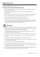
Safety Information To ensure the safe operation and service of the meter, follow these instructions closely. Failure to observe warnings can result in severe injury. Precautions and Preparations for Measurements Ensure that the batteries are connected in the correct polarity and placed in the battery compartment (rear) correctly. Place the red and black test leads into the proper input terminals before making measurements.
CAUTIONS CAUTIONS identify conditions and actions that could cause DAMAGE to the meter or equipment under test. Do not expose the meter to extremes in temperature or high humidity.
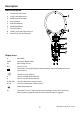
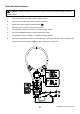
Description Meter Description 1. 2. 3. 4. 5. 6. 7. 8. 9.
Operation NOTES: Read and understand all Warning and Caution statements in this operation manual prior to using this meter. Meter Power The meter is powered by two (2) 1.5V ‘AAA’ batteries. The battery compartment is located on the back of the meter. Press the Power button to switch the device ON or OFF. Low battery indication When the low battery icon appears ( ) the batteries should be replaced immediately, although in-specification measurements can still be made temporarily.
DC and AC Voltage Measurements WARNING: Use the test lead probe covers for CAT IV 600V installations. Do not measure voltages greater than 1000V. CAUTION: When connecting the test leads to the circuit or device under test, connect the black lead before the red; when removing the test leads, remove the red before the black lead. 1. Connect the black test lead into the COM terminal. 2. Connect the red test lead into the ‘V’ terminal. 3. Power the meter using the power button 4.
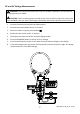
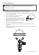
AC Current Measurements WARNING: Ensure that power to the device under test is OFF before starting this procedure. Switch power to the device under test ON only after the clamp has been safely attached to the device under test. CAUTION: Do not move fingers above the LCD at any time during a test. 1. Switch the meter OFF and switch OFF power to the device under test. 2. Switch the meter ON and select ‘A’ with the function switch. The display will show the automatic range icon (AUTO). 3.
Resistance Measurements CAUTION: Disconnect power to the circuit or device under test when making resistance measurements 1. Connect the black test lead into the COM terminal. 2. Connect the red test lead into the ‘Ω’ terminal. 3. Power the meter using the power button 4. Put the function switch to the ‘Ω’ position. 5. The display will show the ‘AUTO’ icon (Auto Range mode). 6. Press the M (Mode) button to select resistance Ω mode. 7.
Continuity Measurements CAUTION: Disconnect power to the circuit or device under test when making continuity measurements 1. Connect the black test lead into the COM terminal. 2. Connect the red test lead into the ‘ohms’ terminal. 3. Power the meter using the power button 4. Put the function switch to the ‘ohms’ position. 5. The display will show the ‘AUTO’ icon (Auto Range mode). 6. Press the M (Mode) button to select continuity mode. 7. The display will show “MANU” icon (Manual Range mode).
Diode Measurements CAUTION: Disconnect power to the circuit or device under test when making diode measurements 1. Connect the black test lead into the COM terminal. 2. Connect the red test lead into the ‘Ω’ terminal. 3. Power the meter using the power button 4. Put the function switch to the ‘Ω’ position. 5. The display will show the ‘AUTO’ icon (Auto Range mode). 6. Press the M (Mode) button to select diode . mode. The display will show the manual mode symbol (MANU). 7.
Capacitance Measurements CAUTION: Discharge the capacitor under test before taking any capacitance measurements 1. Connect the black test lead into the COM terminal. 2. Connect the red test lead into the ‘Ω’ terminal. 3. Power the meter using the power button 4. Put the function switch to the ‘Ω’ position. 5. The display will show the ‘AUTO’ icon (Auto Range mode). 6. Press the M (Mode) button to select the capacitance 7.
Maintenance WARNING: To avoid electrical shock, disconnect the meter from any circuit and turn OFF the meter before opening the case. Do not operate the meter with an open case. Cleaning and Storage Periodically wipe the case with a damp cloth and mild detergent; do not use abrasives or solvents. If the meter is not to be used for 60 days or more, remove the batteries and store them separately.
AC Current 600.0A 0.1 A ±(1.0% + 8 digits) 3000 A 1A ±(1.0% + 10 digits) True rms AC measurements Linearity: ± 0.2% of reading from 10% to 100% of range Conductor position sensitivity: ± (2.0% +15dgts) with the measured conductor a distance from the center > 25mm (1”) External field influence: An increase of ± 1.5% of range max. The recommended distance for conductors from the clamp probe sides is > 200mm.
GENERAL SPECIFICATIONS Clamp Flexible type with locking mechanism 8mm (0.3”) coil diameter 300mm (11.8”) flexible cable length Display 6000 count LCD with multi-function indicators 33.5 x 18.7mm (1.3 x 0.7”) display size Auto range 600.0A and 3000A AC Sampling rate 0.