
User manual


MA3110-en-GB_V1.0 12/16
11
Diode Measurements
CAUTION: Disconnect power to the circuit or device under test when making diode
measurements
1. Connect the black test lead into the COM terminal.
2. Connect the red test lead into the ‘Ω’ terminal.
3. Power the meter using the power button .
4. Put the function switch to the ‘Ω’ position.
5. The display will show the ‘AUTO’ icon (Auto Range mode).
6. Press the M (Mode) button to select diode mode. The display will show the manual
mode symbol (MANU).
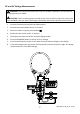
7. When connected as shown in test position 1 a forward current flow is established and
the approximate diode forward voltage (VF) value is displayed. If the diode under test is
defective ‘0.000’ (short circuit) or ‘OL’ (open circuit) will display.
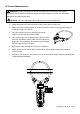
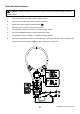
8. When connected as shown in test position 2 a reverse polarity check is made. If the diode
under test is good, ‘OL’ will be displayed. If the diode is defective ‘0.000’ or other values
will be displayed. Proper diode testing should include both polarity measurements.