USER GUIDE 99 Washington Street Melrose, MA 02176 Phone 781-665-1400 Toll Free 1-800-517-8431 Visit us at www.TestEquipmentDepot.com Model SL355 Noise Dosimeter, Datalogger, and Sound Level Meter With PC Interface Copyright © 2012 Extech Instruments Corporation (a FLIR company) All rights reserved including the right of reproduction in whole or in part in any form.
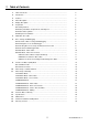
1. Table of Contents 1. Table of Contents ……………………………………………………………….…….. 2 2. Introduction …………………………………………….………………………….…… 3 3. Features …………………………………………………………………………….….. 4 4. Meter Description ……………………………………………………………………... 4 5. Display Description ……………………………………………………………….…… 5 6. Preparation ………………………………………………………………………….…. 6 6.1 Getting Started ……….……………………………………………..……............ 6 6.2 Battery Installation, Replacement, and Disposal ……………………………… 6 6.
2. Introduction Congratulations on the purchase of the Model SL355. The SL355 is a combination Noise Dosimeter, Datalogger, and Sound Level Meter (SLM). The SL355 can be configured manually via push-button navigation of the menu system or through the PC interface using the supplied software (recommended for ease of use).
3. Features Combination Dose Meter, Datalogger, and Sound Level Meter. User-defined measurement configurations. Selectable Criterion Level, Exchange Rate, Threshold, Frequency Weighting, and Response Time settings. Completely configurable using the supplied PC software (recommended). Twenty (20) internal memory locations with a total capacity of 14,400 readings. Download Dose, TWA, and Datalogger data to a PC using supplied PC software.
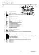
. Display Description 6 12 7 13 8 10 1. Over range indicator Under range indicator 2. 3. 9 1 2 REC 4. Flashing: Timer standby; Solid: Recording 11 3 4 5 Recording Pause indicator ‘Smart’ navigation buttons 5. 6. SPL PK PKZ DOSE LEQ TWA SEL (Sound Pressure Level) (Peak mode: ‘C’ frequency weighting) (Peak mode: Linear ‘Z’ weighting) (%dose) (Equivalent Continuous Sound Level) (Time Weighted Average) (Single Event Noise Exposure Level) 7.
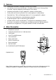
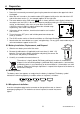
. Preparation 6.1 Getting Started 1. Power the instrument by momentarily pressing the power/menu button at the upper left side of the keypad. 2. When the unit is turned on, the model number (355) appears briefly on the left side of the LCD and the firmware version (1.1, for example) appears on the right side. 3.
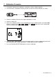
. Calibration Procedure 1. A standard 114db acoustic calibrator is required (as shown in diagram below). 2. Insert the meter’s microphone carefully into the insertion hole of the calibrator (as shown). 3. Switch the calibrator ON and set its output amplitude to 114 db. 4. Switch the meter ON. 5. Access the Calibration mode (CL) by repeatedly pressing the MENU button until the CL XX.
. Dose Testing and Datalogging 8.1 Overview The dosimeter noise survey and datalogging functions operate at the same time. For example, while the %dose and TWA (time weighted average) values are being calculated and displayed (for the dose meter’s noise survey) individual SPL readings are being stored by the datalogger. Noise surveys and logged data are stored in ‘RUNS’ which are memory locations (1 to 20).
DUR (DURATION) Notes: DUR allows the user to select a specific RUN Duration time. When a duration period is set by the user to anything other than OFF, it takes precedence over the Timer setting so that any preset Begin and End times will be ignored. DUR is available in the OPTION mode menu. 6. While testing, the meter’s DATA menu can be navigated (see DATA Menu table and Screen Shots below) as long as the keypad is unlocked.
8.
8.6 SCREEN SHOTS for Dose Meter Operation 8.6.1 Select a Dose Meter Setup from Memory Operation Press Display Shows Change the MENU Mode of Operation repeatedly to SETUP Comments Select SET UP to choose a stored setup configuration. The first display always shows the currently loaded setup, (for example USr, as in the screen shot at left). If no user setups are stored, the up/down arrow buttons will not appear on the LCD. 8.6.2 Measure and Store Dose Data Operation 1. Change Operating Mode 2.
Operation 4. Inspect the setup for the current RUN Press Display Shows Comments To Scroll RUN Begin Time (ddhh:mm) Storage Location for RUN (04) Logging Period (mm:ss) RUN Duration (hh:mm:ss) Criterion Level 90db Selected user setup (for example, ISO with 90db Criterion Level) Threshold 70db Measurement Range Exchange Rate 3db 12 SL355-EU-EN-V1.
5. Inspect data several from the times current RUN User Setup (for example, ISO with 90db Criterion Level) Percent Dose (Dose %) 2 Sound Exposure (Pa h) Some displays offer the use of the and keys to show other parameters. The display updates while the RUN is in progress. 6. Pause RUN / PAUSE The pause icon ( ) is shown. Press this key again to resume the RUN. 7. Lock Keypad and at the same time 8.
8.6.3 Screen Shots for Recalling and Reviewing Dose Data Note that stored data is identified by date (day) and measurement start time (hh:mm) and that up to 20 RUNS can be stored simultaneously. Operation Press Display Shows Comments The meter always powers up in the Sound Level Meter mode. 1. Switch the meter ON 2. Change the Operating Mode MENU 3. Enable Data Recall Display the Start Date & Time for the most recently stored RUN (dd-hh:mm). Select RUN by Start Date & Time. 4.
9. Sound Level Meter (SLM) Mode Use the MENU button to access the SLM mode; the SLM icon will appear on the meter’s LCD when the SLM mode is accessed. The Elapsed Timer will start automatically and the meter will begin displaying the sound pressure level (SPL) measurements in db (decibels); use the RUN/PAUSE button to pause and resume the timer.
9.2 Screen Shots for SOUND LEVEL METER Mode As mentioned, in SLM mode the meter operates as a Type 2 sound level meter. Note that data cannot be logged while the meter is in the SLM mode. Operation Press Display Shows 1. Switch meter ON 2. Review SLM Measurement Comments Start from the Sound Level Meter mode. To Scroll Sound Pressure Level A-Frequency Weighting Fast Time Weighting Measurement Duration Time Press RETURN (RUN/PAUSE) button to Equivalent Continuous Sound Level (Leq) Max.
Operation 3. Inspect and edit the settings Press Display Shows Comments To scroll Press to edit Press Return (RUN/PAUSE) to edit the Range ▲ To change setting Press to confirm Press Return Press Return (RUN/PAUSE) to (RUN/PAUSE) to edit edit Fast/Slow Response Time Max. Peak Press Return (RUN/PAUSE) to Press Return (RUN/PAUSE) edit A/C Frequency weighting to dit th E h R t 4. Editing example Current range is flashing Store the range setting 5.
10. Meter setup using supplied software (Preferred Method) To configure the meter using the supplied software: 1. Install the supplied software onto a PC. 2. Connect the meter to the PC using the supplied USB cable. 3. Run the software program. 4. Refer to the Software User Guide provided on the supplied CD-ROM for detailed instructions on the use of the software program. 11. Configuring the Meter Manually 11.
11.3 SETUP Mode – Screen Shots Operation Press Display Shows Comments The meter powers up in the Sound Level Meter mode. 1. Switch the meter ON 2. Change Mode MENU several times 3. Inspect and edit settings To scroll Press to edit Selecting SET UP mode. The first display shows the name of the currently loaded Setup.
4. Editing example Changing Criterion Level, for example The current Criterion Level will be flashing The stored Criterion Level The new, selected Criterion Level will be flashing 20 SL355-EU-EN-V1.
11.4 OPTION MODE The OPTION menu below lists the parameters that can be viewed and/or configured. Instructions for navigation and use are provided in the menu table and screen shots below. 1. Switch the meter ON using the power/menu button. 2. Use the MENU button to access the OPTION mode. OPTION will be shown when the meter is in the OPTION mode and the current time of day will be displayed (hh:mm:ss). 3. Press ◄ or ► to scroll the parameters in the OPTION mode.
The REPT (Repeat) function allows the test to be repeated a pre-programmed number of times (OFF, 0 to 19). rEPt Press and hold RUN/PAUSE for 3 seconds; the display will flash. Use ▲ or ▼ to change the setting and then press RUN/PAUSE. Press ▼ to move to the next parameter. Tests ‘pairs’ are pairs of Start (BEG) and End times. When a test pair is active, a small ‘L’ appears next to the ‘P’ in ‘Pair’. PAIr To disable the test pair, press RUN/PAUSE and the ‘L’ will switch OFF.
11.6 OPTION Mode - Basic Screen Shots Operation Press Display Shows 1. Switch the meter ON 2. Change Mode 3. Scroll options Comments Start from the Sound Level Meter mode. Current Time. MENU several times To scroll The display cycles through the remaining options: Current Time–hh:mm:ss Current Date–dd:mm:yy Battery status: voltage Timer Status Data Clear – Use this option with caution – ALL DATA CAN BE DELETED! 23 SL355-EU-EN-V1.
11.7 Set the Time & Date in OPTION Mode Operation Press Display Shows Comments 1. Time Option Continued from Step 2 in Section 11.6 2. Enable Time Change Cursors are enabled and the HOURS entry blinks to indicate that it can be edited. 3. Change the entry or Use and to highlight an entry. Use and to change the entry. 4. Save the Changes The new time setting is stored. Repeat this process to set the date. Note that the date format is dd-mm-yy. 24 SL355-EU-EN-V1.
11.8 OPTION Mode - Editing Operation Press Display Shows Comments 1. Select Timer Option Continuing from Section 11.6 2. Switch Timer ON The TIMER is now ON, therefore the programmed Start and Stop times will be used (unless Duration DUR settings are enabled as shown in step 4 below). 3. Logging Period setting 4. DURATION setting 5.
6. Logging Pairs of Start/End times 7. Begin (start) time 8. End time This is the first logging time pair. to enable / disable each Press start/end time pair. When a pair is disabled, the L icon will switch off. This is the first Begin (start) time: ddhh:mm. The day setting is the day of the month. When day “ - - ” is indicated, measurement will start on the current day. Press to enable, use , , and to selecting the Beginning (start) time (dd-hh:mm), and then confirm with .
12. Clear the Meter’s Memory Use this option with care – ALL STORED DATA CAN BE DELETED! Operation Press Display Shows Continued from Section 11.6 1. Select the Clear Memory option 2. Enable Clear Memory Comments Press to Clear all stored data while “SurE--” is displayed or press MENU to abort and select another mode of operation. To toggle steps 1 and 2 27 SL355-EU-EN-V1.
13. Specifications Applicable Standards: IEC61252, ANSI S1.25 – 1992 for dose meter and sound exposure meters IEC 60651 – 1979 Type 2 for sound level meters IEC 60804 – 2000 Type 2 for integration sound level meters ANSI S1.4 – 1983 Type 2 for sound level meters ANSI S1.43 – 1997 for integrating sound level meters Microphone: 1/2-inch electret condenser microphone with 31-inch integral cable.
Logging Period (LP): Seconds: 1, 2, 5, 10, 15, 20, or 30; Minutes: 1, 2, 5, 10, 15, 20, 30, or 60. Logging Capacity: The meter can log 14400 total values spread over 20 memory locations (RUNS). User Setups: Note that one additional user-defined setup configuration can be stored in addition to the factory default configurations shown below.
CE Certification: CE-mark indicates compliance EMC Directive EMC Emission EN50081-1 (1992): Generic emission standard. Part 1: Residential, commercial and light industry EN50081-2 (1993): Generic emission standard. Part 2: Industrial environment CISPR22 (1993): Radio disturbance characteristics of information technology equipment. Class B Limits FCC Rules, Part 15: Complies with the Limits for a Class B digital device EMC Immunity EN50082-1 (1992): Generic immunity standard.
14. Maintenance Care, Cleaning and Storage The SL355 is a delicate precision instrument; when handling, storing, or cleaning the instrument, please observe the following: (a) Storing the Instrument Keep the instrument in a dry place. For long-term storage, remove the batteries. Do not exceed the storage temperature limits: -10 to +60ºC (-14 to +140ºF ) (b) Cleaning the Instrument If the instrument casing becomes soiled, wipe it with a cloth that is lightly dampened with water.
16. Glossary of Terms % DOSE The unit of measure, % DOSE, is used to quantify noise exposure measured during a work shift. 100% dose is the maximum allowable noise exposure in accordance with OSHA, MSHA, DOD, ACGIH, and ISO standards. Most standards specify Criterion Level, Exchange Rate, Response Time, and Frequency weighting for the dosimeter. CRITERION LEVEL To take an on-site noise exposure survey in accordance with standards such as OSHA and MSHA, the dosimeter’s Criterion Level must first be set.