Stufe a Pellet User manual Comfort Idro Duchessa Idro Read the instructions carefully before installation, use and maintenance. The instruction book is an integral part of the product.
INDEX WARNINGS AND SAFETY DEVICES ............................. 4 TECHNICAL FEATURES .............................................. 5 COMFORT IDRO TEMPLATE ....................................... 6 DUCHESSA IDRO TEMPLATE ...................................... 8 WHAT IS THE PELLET? ............................................. 10 PELLET STORAGE ........................................................................ 10 .......................................................................... 10 ...........
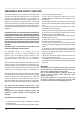
WARNINGS AND SAFETY DEVICES The stoves produced by our establishment are built with attention to the individual components in a way to protect both the user and the installer from any accidents. It is therefore recommended that after any intervention on the product, that authorised staff pay particular attention to the electric connections, especially the stripped parts of the wires.
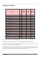
TECHNICAL FEATURES FEATURES Weight Height Width Depth Flue exhaust pipe diameter Air intake pipe diameter Max. heating volume Max. global heat output Max. useful heat output - useful output power to the air - useful output power to the water Minimum global heat output Min. useful heat output - useful output power to the air - useful output power to the water Max. hourly fuel consumption Min.
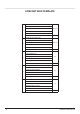
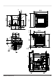
COMFORT IDRO TEMPLATE CONDOTTO ASPIRAZIONE ARIA AIR INTAKE PIPE CONDUIT ASPIRATION AIR A Ø 50 mm ZULUFTANSAUGLEITUNG CONDUCTO DE ASPIRACIÓN DE AIRE CONDUTA DE ASPIRAÇÃO DE AR CONDOTTO ESPULSIONE FUMI FLUE GAS EXHAUST PIPE CONDUIT EXPULSION FUMÉES B Ø 80 mm RAUCHABZUGSLEITUNG CONDUCTO DE EXPULSIÓN DE HUMOS CONDUTA DE EXPULSÃO DE FUMOS MANDATA/USCITA CALDAIA BOILER FLOW OUTLET ALLER/SORTIER CHAUDIERE C 3/4 “ KESSEL-VORLAUF/AUSGANG IDA/SALIDA DE LA CALDERA FORNECIMENTO/SAÍDA DA CALDEIRA RITORNO/INGRES
C 800 D E 777 360 663 56 645 59 74 781 275 223 37 142 42 A 30 97 777 664 B 106 D C E C COMFORT IDRO TEMPLATE D 7
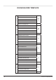
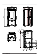
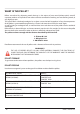
DUCHESSA IDRO TEMPLATE CONDOTTO ASPIRAZIONE ARIA AIR INTAKE PIPE A CONDUIT ASPIRATION AIR Ø 50 mm ZULUFTANSAUGLEITUNG CONDUCTO DE ASPIRACIÓN DE AIRE CONDUTA DE ASPIRAÇÃO DE AR CONDOTTO ESPULSIONE FUMI FLUE GAS EXHAUST PIPE B CONDUIT EXPULSION FUMÉES Ø 80 mm RAUCHABZUGSLEITUNG CONDUCTO DE EXPULSIÓN DE HUMOS CONDUTA DE EXPULSÃO DE FUMOS MANDATA/USCITA CALDAIA BOILER FLOW OUTLET C ALLER/SORTIER CHAUDIERE 3/4 “ KESSEL - VORLAUF/AUSGANG IDA/SALIDA DE LA CALDERA FORNECIMENTO/SAÍDA DA CALDEIRA RITORNO
538 1034 545 31 C 34 B A D 118 203 88 168 868 54 59 47 E G 52 63 DUCHESSA IDRO TEMPLATE 9
WHAT IS THE PELLET? Pellets are realised by subjecting wood shavings i.e. the rejects of pure wood (without paint) sawmill, carpenter products and products from other activities connected to working and transforming wood, to very high pressures. This type of fuel is absolutely ecological as no glues are used to hold it together. In fact, the compactness of the pellets is guaranteed through time by a natural substance that is found in wood: lignin.
LATERAL PELLET FEEDING SUPPORT OPTIONAL KIT If installation has been performed using this optional kit, the insert can be extracted or, more comfortably, use the appropriate lateral chute whenever a relevant opening has been made in the covering of the appliance. For increased clarity regarding the templates, please consult the relative templates manual, which can be downloaded from the site (see back of last page). figure 3.1 ATTENTION: THE MEASUREMENTS ARE INDICATIVE AS THE KIT CAN BE REGULATED.
TEMPLATE WITH LATERAL FEEDING SUPPORT C D 800 A 716 777 664 360 97 ~1277 B 752 E *373 37 560 223 142 640 30 275 106 D 42 400 781 56 645 59 74 ~881 C 12 WHAT IS THE PELLET?
PELLET FRONT FEEDING OPTIONAL KIT The use of this optional kit allows to feed the pellets into the feed-box from the front without extracting the flue, therefore without switching it off. FRONT UPPER FRAME figure 3.2 figure 3.3 figure 3.4 First, remove the front, upper frame by unhooking it from the 2 lateral frames: to do this, lift it by about 10 mm and then pull it towards yourself. The frame must be picked-up using protection for the hands as it could have overheated during functioning.
At this point, take the internal drawer and pull it towards yourself to maximum opening: carry out this SCRAPER operation with the aid of a common protection for the hands or an oven glove in order to prevent burns due to normal overheating of the metal parts during functioning of the appliance. Pour the pellet into the drawer and use the scraper to push it into the flue tank, making sure that it does not INTERNAL remain in the drawer. DRAWER figure 3.8 figure 3.9 figure 3.
During normal functioning the flue must always be as illustrated in the figure i.e. with the drawer completely closed. The front pellet loading drawer must only be open for the loading time in order to prevent product overheating. TEMPLATE WITH FRONT FEEDING SUPPORT STANDARD SUPPLY D E 42 30 223 37 142 645 275 360 A 777 97 709 777 B 709 C 710 106 735 640 800 Installation of the insert with the standard supply envisions switch-off and extraction of the flue for every pellet feed.
SAFETY DEVICES 85°C PELLET TANK BULB If there is overheating inside the feed-box this device blocks pellet feed motor functioning; restoration is FLUE EXHAUST BREAKAGE If the suction device stops, the electronic board manual and must be performed by an authorised technician. immediately blocks the pellet supply.
DEVICES NOT IN THE LIST SAFETY DEVICES FOR CLOSED VESSEL During installation of the stove it is MANDATORY SYSTEM to adjust the plant using a manometer to display According to the UNI 10412-2 (2006) Standard in the water pressure and an automatic vent valve force in Italy, the closed plants must have: calibrated at 3 bar.
TABLE OF THE DEVICES FOR CLOSED VESSEL SYSTEMS PRESENT AND NOT PRESENT IN THE PRODUCT Safety valve COMFORT IDRO DUCHESSA IDRO *1 *7 * (managed by H2O probe * (managed by H2O probe and board firmware) and board firmware) Pump control thermostat Acoustic alarm activation thermostat Water temperature indicator Pressure indicator Acoustic alarm - - * (display) * (display) - - - - * ( board firmware) * ( board firmware) *1 *8 * 2, 3 *13, 14 Circulation system (pump) - * 9, 10 Expansion s
DUCHESSA IDRO SAFETY DEVICE IMAGES 6 Litre expansion vessel *The product expansion vessel is equal to 6 litres. The closed system expansion vessel must be dimensioned between 4% and 6% of the total volume of the plant therefore, the standard closed vessel may not be sufficient in cases of greater water volumes.
ASSEMBLY AND INSTALLATION INSTRUCTIONS FORCED DRAUGHT Air circulation by means of the fan activated by electric motor. The installation must be in compliance with: UNI 10683 (2005) heat generators fed with wood and other solid fuels: installation. The chimneys have to be in compliance with: UNI 9731 (1990) chimneys: classification based on thermal resistance. EN 13384-1 (2006) chimneys thermal and fluid-dynamics calculation method. UNI 7129 point 4.3.
CONNECTION TO THE SMOKE EVACUATION SYSTEM SMOKE CHANNEL OR CONNECTIONS To mount the smoke channels, non-flammable elements will have to be used, ideal for resisting fuel products and their eventual condensing. The use of flexible metal and asbestos cement pipes to connect the appliances to the flue is forbidden, even for pre-existing smoke channels. There must be continuity between the smoke channel and the flue so that the flue does not lean on the generator.
REFERENCES 20 cm M inimum 80 cm2 A B Floor-protection figure 5.3 figure 5.4 A B C C Objects inflammable 200 mm 1,500 mm 200 mm Non-inflammable objects 100 mm 750 mm 100 mm have preferably circular internal section: the square or rectangular sections must have round corners with a radius not lower than 20 mm; have constant internal section, free and independent; have rectangular section with max. ratio between the sides of 1.5.
different dimensions and configuration depending on the covering inclination angle, it is therefore necessary to adopt the minimum heights indicated in the figure layouts below. The chimney cap must not have mechanical intake means. CHIMNEY CAPS, DISTANCES AND POSITIONING Distance between the Minimum chimney height Roof inclination ridge and the chimney (measured from outlet) β A (m) H (m) < 1,85 0.50 m over the ridge 15° > 1,85 1.00 m from roof < 1,50 0.50 m over the ridge 30° > 1,50 1.
distance. The appliance installation must guarantee easy access for cleaning the same appliance, discharge gas pipe and flue. NATIONAL, REGIONAL, PROVINCIAL AND TOWN COUNCIL REGULATIONS It is necessary to bear in mind all laws and national, regional, provincial and town council Standards present in the country the appliance has been installed. HOT AIR DUCTING DIVINA PLUS The Divina Plus model has two pipes positioned in the rear of the stove that allow to duct the heat developed by the machine.
COMFORT IDRO INSTALLATION The Comfort Idro model is supplied with an iron sliding base that allows to install it in a pre-existing flue. This sliding base allows the easy extraction of the insert both for pellet feeding inside the feed-box and for any maintenance or cleaning at the end of the season. If there is no pre-existing flue, one can be built using the insert-holder pedestal (optional kit); in fact, the latter fixes the insert to the floor.
Fix the base using the locking screws. Appropriately connect the conveyor to the flue evacuation piping and the air intake box to the relative intake pipe. Re-position the machine body by repeating the operations carried out previously in the reverse order. Finally, use the Allen wrench to turn the lockbolt anti-clockwise to block movement. To understand whether the insert is correctly attached to the base, connect the plug to the socket and set the master switch at position 1: the display should switch on.
The hopper support can be mounted in both sides of the insert. Adjust the height and the inclination of the hopper on the basis of the flue that will be built. The lower grate of the insert must lie at least 1 cm above the fire surface in covering marble. INSTALLATION OF THE HYDRAULIC PART For the hydraulic connections it is possible to proceed in various ways in relation tot he presence or not of the insert covering structure.
If it is not possible to make a lateral opening in the covering, follow the procedure given below. Release the machine body from the base with the sliding rails using the sequence described previously and fix the base, having already previously positioned the rod for the flexible pipes. Remove the painted cover by means of the 2 screws in the upper part that fix it and also remove the fixing bracket on the left side (see figure 6.14 and 6.15). Side fixing bracket figure 6.15 Painted cover figure 6.
Loosen the ring nuts on the 2 copper pipes and remove the metric screw that fixes the brass block to the machine body. At this point it is possible to separate the brass block with the pipes from the rest of the insert (figure 6.22). Ring nuts Metric screw Gaskets figure 6.21 figure 6.22 figure 6.23 Proceed by connecting the pipes to the support rod and consequently to the system.
65 50 50 figure 6.28 figure 6.27 For correct functioning of the insert, during construction of the flue the measurements between the insert and internal walls of the flue must be respected. From the clearance measurements of the stove given in the technical features, it is necessary to consider at least 50 mm of air in the upper part and on the 2 sides. The flue outlet pipe must always maintain a minimum distance of 50 mm from inflammable parts.
HYDRAULIC SYSTEM CLOSED EXPANSION VESSEL Certain concepts referring to Italian normative UNI 10412-2 (2006) are described in this chapter. As previously described, when installing, all national, regional, provincial and town council Standards in force provided by the country in which the appliance has been installed must be complied with. The appliance must be connected directly to the vessel or to the system expansion vessels unit through a pipe with internal diameter not lower than 18 mm.
PRODUCT FUNCTIONALITY CONTROL BOARD REMOTE CONTROL SENSOR figure 8.1 1 D ON/OFF BUTTON Switches the stove on/off 2-3 D WATER TEMPERATURE SETTING Water T° regulation to be reached 4-5 D FUNCTIONING POWER Machine power (from 1 to 5) CURRENT DAY AND TIME ADJUSTMENT Follow the procedure below to adjust these parameters: 1. Remove and restore the power supply of the stove using the master switch 2. When the word “TIME” appears, press button 5 once. 3.
THE REMOTE CONTROL Using the remote control, there is the possibility of regulating the heating power, the desired temperature and the automatic ignition/switch-off of the appliance. To ignite the stove, press buttons 3 and 5 simultaneously for 1 second. To regulate the heating power use keys 4 and 5, while to regulate the room temperature use keys 2 and 3. To switch the stove off, hold buttons 3 and 5 down simultaneously for 3 seconds.
USER PARAMETERS The following table gives all weekly programmer function parameters. WEEKLY PROGRAMMER VALUE display D1 D2 OFF 0 OFF 1 OFF 2 OFF 1 3 00 4 OFF 5 OFF 6 OFF 1 7 OFF 8 OFF 9 OFF 1 A CONFIRM KEYS Function 2 or 3 ON/OFF Activation/deactivation of the weekly programmer 2 or 3 OFF or from 00:00 to 23:50 Time 1st switch-on 2 or 3 OFF or from 00:00 to 23:50 Time 1st switch-off 2 or 3 ON/OFF 1, ON/OFF 2, ...
OPERATION TO BE PERFORMED SHOW DISPLAY AFTER HAVING PERFORMED THE OPERATION 1 - Press key 3, hold it down and press key 5 5 2 - Press key 2 or 3 to activate (from OFF to ON) the chrono and then press key 5 once to continue 3 - Press key 3 several times until the first switchon time is reached 06:00 (as in example), press key 5 to continue 4 - Press key 3 several times until the first switchoff time is reached 09:00 (as in example), press key 5 to continue MON TUE WED THUR FRI SAT SUN TABLE "B" OFF 1 OF
PELLET FEED ADJUSTMENT The pellet load can be regulated via the display. The problems correlated to the amount of fuel can be divided into 2 categories: LACK OF FUEL: the stove can never develop a suitable flame, remaining very low even at high power. At minimum power the stove tends to almost switch-off taking the stove to “NO PELLETS” alarm mode. When the stove displays the “NO PELLETS” alarm the pellets may be unburned inside the burn pot .
COMFORT IDRO CLEANING - DUCHESSA IDRO Maintenance operations guarantee correct functioning of the product through time. Failure to comply with these operations can jeopardise the safety of the product. Every operation must be performed with the stove completely cold. BURN POT CLEANING The burn pot must be cleaned every day. remove the burn pot from the relevant compartment and free the holes using the appropriate fire irons supplied (see figure 12.
CLEANING HEAT EXCHANGER (COMFORT IDRO) The heat exchangers chamber must be cleaned every month as the soot deposited on the rear of the cast iron hearth wall blocks the regular flow of fumes. To access the heat exchangers, remove the central piece from the hearth wall, following the operations described below: Remove the burn pot from its location Turn the 2 lockbolts, indicated in the figure 12.8, 12.9 manually towards the outside. Hold the extractable cast iron and pull it downwards.
DUCHESSA IDRO CLEANING Maintenance operations guarantee correct functioning of the product through time. Failure to comply with these operations can jeopardise the safety of the product. Every operation must be performed with the stove completely cold. BURN POT CLEANING The burn pot must be cleaned every day. remove the burn pot from the relevant compartment and free the holes using the appropriate fire irons supplied.
DOOR, ASH DRAWER AND BURN POT GASKETS The gaskets guarantee the tightness of the stove and its consequent good functioning. These must be checked regularly: if they should be worn or damages they must be replaced immediately. These operations must be carried out by a qualified technician. To clean the ash drawer, remove the lower door by pressing downwards (figure 11.4), extract the ash drawer and empty it (figure 11.5). figure 11.5 figure 11.4 N.B.
PRODUCT DISPLAY TABLES SIGNALS Display STAND-BY Reason Cooling stand-by Stove off due to the DOFF effect of the “Daynight function” . COOL/ No current on the main BLACK OUT power supply. Burn pot cleaning in CLEAN. progress Solution The stove can only be switched back on when it completely cold Pressing key 1 for 3 seconds, the stove will pass to OFF. After the complete cooling cycle the stove will re-ignite automatically. The automatic cleaning does not start if the stove is in 1st power.
ALARMS Signals Display FUME FAIL FUMES TC HIGH TEMP DEPR FAIL NO IGN NO IGN BLACK OUT NO PELLET HIGH H2O STAND-BY + ALARM TELEPHONE N°. ---------- 42 Reason Solution It is on in the presence of one of the alarms described below and is accompanied by the relative signal in display D1, which Indicates the presence of an alarm identifies the cause. To reset the alarm, just hold key 1 down for 3 seconds when the stove is completely cold.
WARRANTY CONDITIONS EXTRAFLAME S.p.A., with offices in via dell’Artigiananto 10 Montecchio Precalcino (VI), guarantees this product for 2 (two) YEARS from purchase date for manufacturer and material faults. The warranty becomes void in case the defect of conformity is not filed with the dealer within two months from date of its finding. The responsibility of EXTRAFLAME S.p.A.
Stufe a Pellet EXTRAFLAME S.p.a. Via Dell’Artigianato, 10 36030 MONTECCHIO PRECALCINO Vicenza - ITALY Tel. 0445/865911 Fax 0445/865912 http://www.lanordica-extraflame.com E-mail: info@extraflame.com Extraflame reserves the right to vary the features and data given in this document at any time without forewarning, in order to improve its products. This manual, therefore, cannot be considered as a contract for third parties. This document is available at www.extraflame.