
User manual


COMFORT IDRO INSTALLATION
29
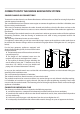
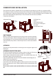
Loosen the ring nuts on the 2 copper pipes and remove the metric screw that xes the brass block to the machine
body. At this point it is possible to separate the brass block with the pipes from the rest of the insert ( gure 6.22).
Metric screw
Gaskets
Ring nuts
gure 6.21
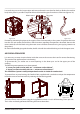
gure 6.22
gure 6.23
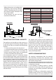
Proceed by connecting the pipes to the support rod and consequently to the system. Re-position the insert
into the rails and restore the initial brass block situation, repeating the operations described above in the
reverse order ( rst x the block using the metric screw and then connect the ring nuts paying attention to
the gaskets)
Re-mount the exible pipe guide bracket, the left side with the relative blocking rod and the upper cover.
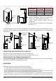
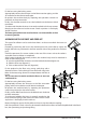
AIR CIRCULATION PIPES
It is necessary to create air recirculation inside the structure that covers the insert for correct functioning.
This prevents the appliance from over-heating.
To guarantee this, just realise one or more openings in the lower part and in the upper part of the
covering.
The following measurements must be respected:
Lower part (cold air inlet) with tot
D
minimum surface 550 cm.
Upper part (hot air outlet) with tot
D
minimum surface 500 cm.
This ventilation system is totally independent from the air intake for combustion!!
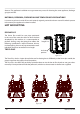
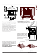
To protect from any over-heating, the Comfort P80 is supplied with a probe that analyses the temperature
inside the structure and intervenes by reducing the functioning power.
gure 6.24 gure 6.25 gure 6.26
The lateral frames must be xed using the 2 supplied burnished 4.2 x 9.5 self-threading screws per side.
The 2 sides are already perforated for xing the frames themselves.