Stufe a Pellet PELLET STOVES User manual DUCHESSA IDRO DUCHESSA IDRO STEEL Read the instructions carefully before installation, use and maintenance. The instruction book is an integral part of the product.
Congratulations! You are now the owner of an Extraflame stove The Extraflame pellet stove is a great heating solution developed from the most advanced technology with top quality machining and modern design, aimed at making you enjoy the fantastic sensation that the heat of a flame gives, in complete safety. This manual will help you to use your stove correctly. It must be read with great attention before use.
Index Chapter 1 WARNINGS AND SAFETY DEVICES.......................................................................................................... 7 Chapter 2 TECHNICAL FEATURES ............................................................................................................................. 8 DIMA DUCHESSA IDRO .........................................................................................................................................................9 DIMA DUCHESSA IDRO STEEL ...
COMMISSIONING CHECKS ......................................................................................................................................... 25 FEEDING WATER FEATURES ....................................................................................................................................... 25 FILLING THE PLANT .......................................................................................................................................................
Chapter 1 WARNINGS AND SAFETY DEVICES The stoves produced by our establishment are built with attention to the individual components in a way to protect both the user and the installer from any accidents. It is therefore recommended that after any intervention on the product, authorised staff pays particular attention to the electric connections, especially the stripped parts of the wires.
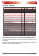
Chapter 2 TECHNICAL FEATURES Features Weight Height Width Depth Flue exhaust pipe diameter Air intake pipe diameter Max. global heat output Max. useful heat output - useful output power to the air - useful output power to the water Minimum global heat output Min. useful heat output - useful output power to the air - useful output power to the water Max. hourly fuel consumption Min.
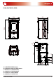
Chapter 2 DIMA DUCHESSA IDRO 538 1034 545 31 C 34 E G A D 118 203 88 168 B 47 868 54 59 52 63 A = AIR INTAKE PIPE Ø 50 mm B = FLUE GAS EXHAUST PIPE Ø 80 mm C = BOILER 3/4 “ FLOW/OUTLET D = BOILER 3/4 “ RETURN/INLET E = 3 BAR 1/2 “ SAFETY DRAIN G = BOILER 3/4 “ OUTLET AIR TECHNICAL FEATURES 9
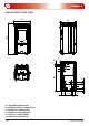
Chapter 2 DIMA DUCHESSA IDRO STEEL 538 31 1034 545 C 34 A D 118 203 88 168 868 B 47 E G 54 59 52 63 A = AIR INTAKE PIPE Ø 50 mm B = FLUE GAS EXHAUST PIPE Ø 80 mm C = BOILER 3/4 “ FLOW/OUTLET D = BOILER 3/4 “ RETURN/INLET E = 3 BAR 1/2 “ SAFETY DRAIN G = BOILER 3/4 “ OUTLET AIR 10 TECHNICAL FEATURES
Chapter 3 WHAT IS THE PELLET? Pellets are realised by subjecting wood shavings i.e. the rejects of pure wood (without paint) sawmill, carpenter products and products from other activities connected to working and transforming wood, to very high pressures. This type of fuel is absolutely ecological as no glues are used to hold it together. In fact, the compactness of the pellets is guaranteed through time by a natural substance that is found in wood: lignin.
Chapter 4 SAFETY DEVICES FLUE EXHAUST BREAKAGE If the suction device stops, the electronic board immediately blocks the pellet supply. PELLET FEED MOTOR STOP If the motor reducer stops for any reason, the stove goes into alarm mode and the fumes motor continues to function in order to expel all combustion gas until the minimum cooling level is reached. DOOR MICRO SWITCH When the stove door is opened, a safety micro switch blocks fuel feeding.
Chapter 4 WATER OVERHEATING SAFETY VIA 100° C BULB When the temperature of the water inside the product is in proximity of 100°C, pellet feeding is blocked. If the bulb trips, restoration of the safety device is manual and must be performed by an authorised technician. The restoration of 100°C safety device is not under warranty unless the after-sales centre can show the presence of a faulty component.
Chapter 4 Adjustment automatic circuit breaker switch Automatic circuit breaker switch (block thermostat) Circulation system Expansion system* Safety dissipation system incorporated with the generator with thermal safety valve (self-activated), whenever the appliance does not have a temperature self-adjustment system. The temperature safety sensors must be in place on the machine at a distance no greater than 30 cm from the flow connection.
Chapter 4 Door micro switch Rearm of the tank bulb 85°C SAFETY DEVICES Rearm water bulb 100°C 15
Chapter 5 ASSEMBLY AND INSTALLATION INSTRUCTIONS The installation must be in compliance with: UNI 10683 (2005) heat generators fed with wood and other solid fuels: installation. The chimneys have to be in compliance with: UNI 9731 (1990) chimneys: classification based on thermal resistance. EN 13384-1 (2006) chimneys thermal and fluid-dynamics calculation method. UNI 7129 point 4.3.3 Fire Department dispositions, local rules and prescriptions. UNI 1443 (2005) chimneys: general requisites.
Chapter 5 SMOKE EVACUATION SYSTEMS Flue gas exhaust system independent from the appliance constituted by a fitting or smoke channel, chimney or individual flue and chimney cap. FORCED DRAUGHT Air circulation by means of the fan activated by electric motor. NATURAL DRAUGHT Draught which determinates in a chimney/flue for effect of the volume mass difference existing between smoke (hot) and surrounding atmosphere air, without any mechanical intake aid installed inside it or at its peak.
Chapter 5 CONNECTION TO THE SMOKE EVACUATION SYSTEM SMOKE CHANNEL OR CONNECTIONS To mount the smoke channels, non-flammable elements will have to be used, ideal for resisting fuel products and their eventual condensing. The use of flexible metal and asbestos cement pipes to connect the appliances to the flue is forbidden, even for pre-existing smoke channels. There must be continuity between the smoke channel and the flue so that the flue does not lean on the generator.
Chapter 5 It is forbidden to have other air supply channels and pipes for plant engineering, especially if over-sized, transit inside the smoke channels. The mounting of manual draught adjustment devices on forced draught appliances is forbidden.
Chapter 5 Chimney cap wind-proof <3m 3-5% Flue Inspection Inspection figure 5.6 figure 5.7 <3m External pipe insulated 45° 45° Inspection Inspection figure 5.8 20 figure 5.
Chapter 5 APPLIANCE CONNECTION TO THE FLUE AND FUEL PRODUCTS EVACUATION The flue must receive the discharge from only one heat generator. The direct discharge towards closed spaces is forbidden, even with clear sky. The direct discharge of the fuel products must be at roof and the smoke pipe must have the features provided in the “Chimney or individual flue” section.
Chapter 5 CHIMNEY CAPS, DISTANCES AND POSITIONING Distance between Roof Minimum chimney height the ridge and the inclination (measured from outlet) chimney β A (m) H (m) < 1,85 0,50 m over the ridge 15° > 1,85 1,00 m from roof < 1,50 0,50 m over the ridge 30° > 1,50 1,30 m from roof < 1,30 0,50 m over the ridge 45° > 1,30 2,00 m from roof < 1,20 0,50 m over the ridge 60° > 1,20 2,60 m from roof CONNECTION TO EXTERNAL AIR INLETS The appliance must be able to use the necessary air to guarantee regular functi
Chapter 6 HYDRAULIC SYSTEM Certain concepts referring to Italian normative UNI 10412-2 (2006) are described in this chapter. As previously described, when installing, all national, regional, provincial and town council Standards in force provided by the country in which the appliance has been installed must be complied with. TYPE OF SYSTEM There are two different types of plant: Open vessel plant and closed vessel plant. The product has been designed and realised to work with closed vessel systems.
Chapter 6 SAFETY VALVES The load capacity of the safety valve must allow the discharge of a quantity of vapour, not lower than: Q / 0,58 [kg/h] where: Q is the useful outlet power to the generator water expressed in kilowatt. The diameter of the minimum net transversal section of the valve inlet must not be lower than 15 mm. The valve load pressure, equal to the calibration pressure, increased by the overpressure, cannot exceed the maximum exercise pressure of the heat generator.
Chapter 6 Where it is necessary to separate the individual heat generator from the expansion vessel or expansion vessels unit, a three-way tap must be applied on the connection piping between the generator and the vessel, in order to ensure, in every position, the connection of the generator with the expansion vessel or with the atmosphere. The expansion vessels, the connecting pipes, the bleed pipes and drain pipes must be protected from freezing, where this phenomenon occurs.
Chapter 7 PRODUCT FUNCTIONALITY CONTROL BOARD REMOTE CONTROL SENSOR D1 D2 figure 7.2 1 D ON/OFF BUTTON By pressing button 1 it is possible to switch the stove on and off automatically. 2-3 D WATER TEMPERATURE SETTING Buttons 2 and 3 are used to adjust the water temperature which will then be distributed inside the plant. 4-5 D FUNCTIONING POWER The power can be adjusted using buttons 4 and 5; the machine has 5 different powers Display D1 to view the various messages. Display D2 to view the power set.
Chapter 7 BASIC INSTRUCTIONS The stove you have purchased uses pellet fuel. This type of material is obtained from natural waste from the machining of wood. By means of a special process that does not require the use of any binding agent and additive, the waste is compressed in industrial machinery under high pressure and they become solid wooden pellets. IT IS PROHIBITED TO BURN NON-PELLETISED RAW MATERIALS INSIDE OUR STOVES.
Chapter 7 WATER TEMPERATURE ADJUSTMENT The appliance can control the water temperature through a digital probe which automatically adjusts the machine functioning when nearing the desired temperature. When the stove is started and has entered normal functioning mode, display D1 will shows the water temperature. Adjust the desired water temperature using keys 2 and 3.
Chapter 7 PUMP FUNCTIONING The standard installation of the pump inside the product starts the water circulation when the temperature of the water inside the stove reaches approx. 60°C. The pump will always function to circulate the water inside the plant, unless the water returning to the stove is below 60°C. As soon as the product switches on, it is normal for the pump to function intermittently, given the thermal exchange with the plant.
Chapter 8 THE REMOTE CONTROL The heating power, the plant set water and the automatic appliance ignition/switch off, can be adjusted using the remote control. S = Indicator light indicating the pressing of every key. S Display keys correspondence with remote control keys P2 P5 P3 P4 1 = p3+p5 2 = p2 3 = p3 4 = p4 5 = p5 figure 8.1 To switch on the stove, simultaneously press buttons 3 and 5 for 1 second; the appliance will automatically enter the ignition phase.
Chapter 9 ADDITIONAL EXTERNAL ROOM THERMOSTAT INSTALLATION N.B. : Installation must be performed by an authorised technician 1. Switch the appliance off using the master switch positioned on the rear of the stove. 2. Remove the plug from the socket. 3. Refer to the electrical layout to remove the default bridge and connect the two thermostat cables on to the relative clamps positioned on the rear of the machine; one is red and the other black.
Chapter 10 USER PARAMETERS USER PARAMETERS WEEKLY PROGRAMMER Display D2 Function 0 Act./Deact.
Chapter 10 Let’s suppose that the weekly programmer function is to be used and 3 time periods are to be used in the following way: 1st time span: from 08:00 to 12:00 every day of the week excluding Saturday and Sunday 2nd time span: from 15:00 to 22:00 only Saturday and Sunday 3rd time span: not used Let’s set the data. Parameter 0 (D2=UT 0(flashing); D1=ON] Use buttons 2 and 3 to activate the weekly programmer by setting the value on display D2 at ON. Parameter 1 (D2=UT 1(flashing); D1=E.g.
Chapter 10 Parameter 6 (D2=UT 6(flashing); D1=E.g. “22:00:00”] Use buttons 2 or 3 to set “22:00”, which corresponds to the switch-off time of the 2nd time span. To confirm and continue programming, press button 5. Press button 4 to go back to the previous parameter. Parameter 7 (D2=UT 7(flashing); D1=E.g. “OFF 1”] Activate the second time span only Saturday and Sunday. To do this use keys 2 and 3 in the following way: a. key 3 - scroll the various days b.
Chapter 10 TO DEACTIVATE THE WEEKLY PROGRAMMER enter user programming by pressing key 3 and holding it down press key 5. Shift using button 5 until “CHRONO” appears on display D1 and set “OFF” in display D2 using keys 2 and 3. Successively press key 1 to confirm and escape. The manual controls, from the display or remote control, always remain priority with respect to programming.
Chapter 10 LACK OF FUEL EXCESS OFFUEL Increase the percentage value by 5 points and try the stove with the new calibration for at least half an hour. If the problem is attenuated, but not solved, increase by another 5 points. Repeat the operation until the problem is solved. If the problem cannot be resolved, contact the after-sales service. Decrease the percentage value by 5 points and try the stove with the new calibration for at least half an hour.
Chapter 11 CLEANING Maintenance operations guarantee correct functioning of the product through time. Failure to comply with these operations can jeopardise the safety of the product. BRAZIER CLEANING The brazier must be cleaned every day. Remove the brazier from the relevant compartment and free the holes using the appropriate fire irons supplied. remove the ash from the pot using a suction device suck the ash deposited in the pot compartment figure 11.
Chapter 11 DOOR, ASH DRAWER AND BRAZIER GASKETS The gaskets guarantee the tightness of the stove and its consequent good functioning. These must be checked regularly: if they should be worn or damages they must be replaced immediately. These operations must be carried out by a qualified technician. To clean the ash drawer, remove the lower door by pressing downwards (figure 11.4), extract the ash drawer and empty it (figure 11.5). figure 11.4 figure 11.5 N.B.
Chapter 12 PRODUCT DISPLAY TABLES SIGNALS Signals Reason Display Solution ATTE A new ignition is attempted when the stove has just been switched off (normal switch-off or caused by an alarm). When the stove switches off (normal or caused by an alarm) it is necessary to wait until complete fumes motor switch off and then clean the brazier. The stove can only be re-ignited when these operations have been performed. STBY Stove off waiting for re-ignition.
Chapter 12 ALARMS Signals Display D1 Reason Solution Indicates the presence of an alarm It is on in the presence of one of the alarms described below and is accompanied by the relative signal in display D1, which identifies the cause. To reset the alarm, just hold key 1 down for 3 seconds when the stove is completely cold. If flashing it indicates the deactivation of the depression sensor. The sensor restoration operations must be carried out by an authorised technician.
Chapter 12 Every time the stove displays one of the alarms listed above it will switch-off automatically. Attempt to release the alarm with stove The stove will block any release attempt during this phase, ATTE + ALLARME still in cooling mode showing the alarm itself and ATTE alternately on the display. The alarm can only be released using button 1 when it switchoff has been completed. NR. TELEFONO ---------- Telephone number display.
Chapter 12 LUMINOUS INDICATORS Signals Reason Indicator light It indicates the Weekly programmer function Solution It is on/off when the Weekly programmer function is active/deactivated. For all settings relative to the following function see the “Weekly programmer” function. Indicates modulation of When LED flashes the fumes motor is modulating, if permanent it is not. the fumes motor 42 It indicates deactivation of the ign-plug It is off/on when the electrode is activated/deactivated.
Chapter 13 WARRANTY EXTRAFLAME S.p.A. reminds you that the manufacturer is the owner of the rights envisioned by the Legislative Decree dated 2 February 2002, n. 24 and the following warranty does jeopardise these rights. This warranty certificate, granted by Extraflame S.p.A., with offices in Montecchio Precalcino (VI), via dell’Artigianato 10, refers to all stove components supplied by Extraflame S.p.A.
Chapter 13 Extraflame S.p.A. is not liable for any damage/injury that can, directly or indirectly, affect persons, objects and pets as a consequence of failure to comply with the prescriptions indicated in this manual and the standards in force regarding installation and maintenance of the appliance.
Chapter 14 QUALITY CONTROL Document to be kept and produced if an intervention is requested under warranty Name Surname Address Post code Municipality County Telephone Model Serial N°.
Notes 46
Notes 47
Stufe a Pellet EXTRAFLAME S.p.a. Via Dell’Artigianato, 10 36030 MONTECCHIO PRECALCINO Vicenza - ITALY Tel. 0445/865911 Fax 0445/865912 http://www.lanordica-extraflame.com E-mail: info@extraflame.com Extraflame reserves the right to vary the features and data given in this document at any time without forewarning, in order to improve its products. This manual, therefore, cannot be considered as a contract for third parties. This document is available at www.extraflame.