ExtremeSwitching 200 Series: Command Reference Guide 122040-03 Rev.
Copyright © 2019 Extreme Networks, Inc. All rights reserved. Legal Notice Extreme Networks, Inc. reserves the right to make changes in specifications and other information contained in this document and its website without prior notice. The reader should in all cases consult representatives of Extreme Networks to determine whether any such changes have been made. The hardware, firmware, software or any specifications described or referred to in this document are subject to change without notice.
Table of Contents Preface......................................................................................................................................... 6 Text Conventions...................................................................................................................................................................6 Providing Feedback to Us..............................................................................................................................................
Table of Contents System Utility and Clear Commands.......................................................................................................................182 Power Over Ethernet Commands.............................................................................................................................194 Simple Network Time Protocol Commands.......................................................................................................200 Time Zone Commands..................
Table of Contents Interface Error Disable and Auto Recovery........................................................................................................ 492 UniDirectional Link Detection Commands.......................................................................................................... 495 Chapter 6: Routing Commands........................................................................................... 499 Address Resolution Protocol Commands..................................
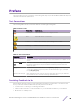
Preface This section discusses the conventions used in this guide, ways to provide feedback, additional help, and other Extreme Networks publications. Text Conventions The following tables list text conventions that are used throughout this guide. Table 1: Notice Icons Icon New! Notice Type Alerts you to... General Notice Helpful tips and notices for using the product. Note Important features or instructions. Caution Risk of personal injury, system damage, or loss of data.
Preface If you would like to provide feedback to the Extreme Networks Information Development team about this document, please contact us using our short online feedback form. You can also email us directly at documentation@extremenetworks.com.
Preface Archived Documentation (for earlier versions and legacy products) www.extremenetworks.com/support/documentation-archives/ Release Notes www.extremenetworks.com/support/release-notes Open Source Declarations Some software files have been licensed under certain open source licenses. More information is available at: www.extremenetworks.com/support/policies/software-licensing/. ExtremeSwitching 200 Series: Command Reference Guide for version 01 .02.04.
1 Using the Command-Line Interface Command Syntax Command Conventions Common Parameter Values unit/slot/port Naming Convention Using the “No” Form of a Command Executing Show Commands CLI Output Filtering Command Modes Command Completion and Abbreviation CLI Error Messages CLI Line-Editing Conventions Using CLI Help Accessing the CLI The command-line interface (CLI) is a text-based way to manage and monitor the system.
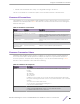
Using the Command-Line Interface • Default shows the default value, if any, of a configurable setting on the device. The show commands also contain a description of the information that the command shows. Command Conventions The parameters for a command might include mandatory values, optional values, or keyword choices. Parameters are order-dependent. Table 3 describes the conventions this document uses to distinguish between value types.
Using the Command-Line Interface Table 4: Parameter Descriptions (continued) Parameter Description Interface or unit/ slot/port Valid slot and port number separated by a forward slash. For example, 0/1 represents slot number 0 and port number 1. Logical Interface Represents a logical slot and port number. This is applicable in the case of a portchannel (LAG (Link Aggregation Group)). You can use the logical unit/slot/port to configure the port-channel.
Using the Command-Line Interface Table 6: Type of Ports Port Type Description Physical Ports The physical ports for each slot are numbered sequentially starting from one/ For example, port 1 on slot 0 (an internal port) for a stand alone (nonstacked) switch is 1/0/1, port 2 is 1/0/2, port 3 is 1/0/3, and so on. Logical Interfaces Port-channel or Link Aggregation Group (LAG) interfaces are logical interfaces that are only used for bridging functions.
Using the Command-Line Interface content does not scroll off the terminal screen until the user presses a key to continue. --More-or (q)uit is displayed at the end of each page. • When pagination is enabled, press the return key to advance a single line, press q or Q to stop pagination, or press any other key to advance a whole page. These keys are not configurable.
Using the Command-Line Interface Command Modes The CLI groups commands into modes according to the command function. Each of the command modes supports specific 200 Series software commands. The commands in one mode are not available until you switch to that particular mode, with the exception of the User EXEC mode commands. You can execute the User EXEC mode commands in the Privileged EXEC mode. The command prompt changes in each command mode to help you identify the current mode.
Using the Command-Line Interface Table 7: CLI Command Modes (continued) Command Mode Prompt Mode Description Interface LAG Config Extreme nnn (Interface lag lag-intf- Enters LAG interface configuration mode for the specified LAG. num)# Line Console Extreme nnn (config-line)# Contains commands to configure outbound telnet settings and console interface settings, as well as to configure console login/enable authentication.
Using the Command-Line Interface Table 7: CLI Command Modes (continued) Command Mode Prompt Mode Description Management Access-list Config Extreme nnn (config-macal)# Allows you to create a Management Access-List and to enter the mode containing Management Access-List configuration commands. TACACS Config Extreme nnn (Tacacs)# Contains commands to configure properties for the TACACS servers.
Using the Command-Line Interface Table 8: CLI Mode Access and Exit (continued) Command Mode Interface Config Access Method From the Global Config mode, enter: interface interface interface interface unit/slot/port or loopback id or tunnel id unit1/slot1/port1,unit2/slot2/port2,...
Using the Command-Line Interface Table 8: CLI Mode Access and Exit (continued) Command Mode Access Method Task-Group Configuration From the Global Config mode, enter the taskgroup taskgroup-name Mode command. DHCP Pool Config From the Global Config mode, enter the ip dhcp pool pool-name command. DHCPv6 Pool Config From the Global Config mode, enter the ip dhcpv6 pool pool-name command. Stack Global Config Mode From the Global Config mode, enter the stack command.
Using the Command-Line Interface CLI Line-Editing Conventions Table 10 describes the key combinations you can use to edit commands or increase the speed of command entry. You can access this list from the CLI by entering help from the User or Privileged EXEC modes. Table 10: CLI Editing Conventions Key Sequence Description [DEL] or [Backspace] Delete previous character. [Ctrl]+[A] Go to beginning of line. [Ctrl]+[E] Go to end of line. [Ctrl]+[F] Go forward one character.
Using the Command-Line Interface Enter a question mark (?) after each word you enter to display available command keywords or parameters. (Extreme 220) #network ? ipv6 Configure IPv6 parameters for system network. javamode Enable/Disable. mac-address Configure MAC Address. mac-type Select the locally administered or burnedin MAC address. mgmt_vlan Configure the Management VLAN ID of the switch. parms Configure Network Parameters of the device.
2 Stacking Commands Dedicated Port Stacking Stack Port Commands Stack Firmware Synchronization Commands This chapter describes the stacking commands available in the 200 Series CLI. Caution The commands in this chapter are in one of two functional groups: • Show commands display switch settings, statistics, and other information. • Configuration commands configure features and options of the switch. For every configuration command, there is a show command that displays the configuration setting.
Stacking Commands Format member unit switchindex Mode Stack Global Config Note Switch index can be obtained by executing the show supported switchtype command in User EXEC or Privileged EXEC mode. no member This command removes a switch from the stack. The unit is the switch identifier of the switch to be removed from the stack. This command is executed on the Primary Management Unit.
Stacking Commands movemanagement This command moves the Primary Management Unit functionality from one switch to another. The fromunit is the switch identifier on the current Primary Management Unit. The tounit is the switch identifier on the new Primary Management Unit. Upon execution, the entire stack (including all interfaces in the stack) is unconfigured and reconfigured with the configuration on the new Primary Management Unit.
Stacking Commands Format slot unit/slot cardindex Mode Global Config Note Card index can be obtained by executing show supported cardtype command in User EXEC or Privileged EXEC mode. no slot This command removes configured information from an existing slot in the system. Format no slot unit/slot cardindex Mode Global Config Note Card index can be obtained by executing show supported cardtype command in User EXEC or Privileged EXEC mode.
Stacking Commands set slot power This command configures the power mode of the slot(s) and allows power to be supplied to a card located in the slot. If you specify all, the command is applied to all slots, otherwise the command is applied to the slot identified by unit/slot. Use this command when installing or removing cards. If a card or other module is present in this slot, the power mode is applied to the contents of the slot.
Stacking Commands Default Cumulative Summing Format stack-status sample-mode {cumulative | history} [max-samples 100 - 500] Mode Stack Global Config Mode Parameter Description sample-mode Mode of sampling cumulative Tracks the sum of received time stamp offsets cumulatively. history Tracks history of received timestamps max-samples Maximum number of samples to keep The following command sets the sampling mode to cumulative summing.
Stacking Commands Column Meaning Pluggable Cards are pluggable or non-pluggable in the slot. Power Down Whether the slot can be powered down. If you supply a value for unit/slot, the following additional information appears: Column Meaning Inserted Card Model Identifier The model identifier of the card inserted in the slot. Model Identifier is a 32character field used to identify a card. This field is displayed only if the slot is full. Inserted Card Description The card description.
Stacking Commands If you do not supply a value for cardindex, the following output appears: Column Meaning Card Index (CID) The index into the database of the supported card types. This index is used when preconfiguring a slot. Card Model Identifier The model identifier for the supported card type. If you supply a value for cardindex, the following output appears: Column Meaning Card Type The 32-bit numeric card type for the supported card.
Stacking Commands SW Switch Status Model ID Model ID Status Version --- ---------- --------- ------------- ------------- ------------- ----------1 Mgmt Sw 220-24t-10GE2 220-24t-10GE2 OK 1.1.1.10 2 Stack Mbr Oper Stby 220-48t-10GE4 220-48t-10GE4 OK 1.1.1.10 When you specify a value for unit, the following information displays. Column Meaning Management Status Whether the switch is the Primary Management Unit, a stack member, or the status is unassigned.
Stacking Commands show supported switchtype This command displays information about all supported switch types or a specific switch type. Format show supported switchtype [switchindex] Mode User EXEC Privileged EXEC If you do not supply a value for switchindex, the following output appears: Column Meaning Switch Index (SID) The index into the database of supported switch types. This index is used when preconfiguring a member to be added to the stack.
Stacking Commands Column Meaning Unit The unit number. Interface The slot and port numbers. Configured Stack Mode Stack or Ethernet. Running Stack Mode Stack or Ethernet. Link Status Status of the link. Link Speed Speed (Gbps) of the stack port link. show stack-port counters This command displays summary data counter information for all interfaces. Format show stack-port counters [1-n | all] Mode Privileged EXEC Column Meaning Unit The unit number.
Stacking Commands this information. In verbose mode, the statistics and counters for RPC, transport, CPU, and transport RX/TX modules are displayed. Format show stack-port diag [1-n | all] [verbose] Mode Privileged EXEC Column Meaning Unit The unit number. Interface The slot and port numbers. Diagnostic Entry1 80-character string used for diagnostics. Diagnostic Entry2 80-character string used for diagnostics. Diagnostic Entry3 80-character string used for diagnostics.
Stacking Commands ----------------------------------------HPC RPC statistics/counters from unit..2 ----------------------------------------Registered Functions........................... Client Requests................................ Server Requests................................ Server Duplicate Requests...................... Server Replies................................. Client Remote Tx............................... Client Remote Retransmit Count................. Tx without Errors...................
Stacking Commands Tx CoS[7] Reserve.............................. Tx Pkt Pool Size............................... Tx Available Pkt Pool Size..................... Tx failed/error Count.......................... Rx Pkt Pool Size............................... -----------------------------------------Next Hop statistics/counters from unit..2 -----------------------------------------State Initialization........................... Component Setup................................ Thread Priority..................
Stacking Commands Format show stack-port stack-path {1-8 | all} Mode Privileged EXEC Stack Firmware Synchronization Commands Stack Firmware Synchronization (SFS) provides the ability to automatically synchronize firmware for all stack members. If a unit joins the stack and its firmware version is different from the version running on the stack manager, the SFS feature can either upgrade or downgrade the firmware on the mismatched stack member.
Stacking Commands boot auto-copy-sw allow-downgrade Use this command to allow the stack manager to downgrade the firmware version on the stack member if the firmware version on the manager is older than the firmware version on the member. Default Enabled Format boot auto-copy-sw allow-downgrade Mode Privileged EXEC no boot auto-copy-sw allow-downgrade Use this command to prevent the stack manager from downgrading the firmware version of a stack member.
3 Management Commands Network Interface Commands Console Port Access Commands Telnet Commands Secure Shell Commands Management Security Commands Hypertext Transfer Protocol Commands Access Commands User Account Commands SNMP Commands RADIUS Commands TACACS+ Commands Configuration Scripting Commands Prelogin Banner, System Prompt, and Host Name Commands This chapter describes the management commands available in the 200 Series CLI.
Management Commands do (Privileged EXEC commands) This command executes Privileged EXEC mode commands from any of the configuration modes. Format do Priv Exec Mode Command Mode • • • • Global Config Interface Config VLAN Config Routing Config The following is an example of the do command that executes the Privileged EXEC command script list in Global Config Mode.
Management Commands serviceport protocol dhcp This command enables the DHCPv4 client on a Service port. If the client-id optional parameter is given, the DHCP client messages are sent with the client identifier option. Default none Format serviceport protocol dhcp [client-id] Mode Privileged EXEC There is no support for the no form of the command serviceport protocol dhcp client-id.
Management Commands Default None Format network protocol dhcp [client-id] Mode Global Config There is no support for the no form of the command network protocol dhcp client-id. To remove the client-id option from the DHCP client messages, issue the command network protocol dhcp without the client-id option. The command network protocol none can be used to disable the DHCP client and client-id option on the interface. The following shows an example of the command.
Management Commands network javamode This command specifies whether the switch should allow access to the Java applet in the header frame of the web interface. When access is enabled, the Java applet can be viewed from the web interface. When access is disabled, users cannot view the Java applet. Default enabled Format network javamode Mode Privileged EXEC no network javamode This command disallows access to the Java applet in the header frame of the web interface.
Management Commands Column Meaning byte. Bit 1 of byte 0 must be set to a 1 and bit 0 to a 0, that is, byte 0 should have the following mask 'xxxx xx10'. The MAC address used by this bridge when it must be referred to in a unique fashion. We recommend that this be the numerically smallest MAC address of all ports that belong to this bridge. However it is only required to be unique. When concatenated with dot1dStpPriority a unique Bridge Identifier is formed which is used in the Spanning Tree Protocol.
Management Commands Column Meaning Subnet Mask The IP subnet mask for this interface. The factory default value is 0.0.0.0. Default Gateway The default gateway for this IP interface. The factory default value is 0.0.0.0. IPv6 Administrative Mode Whether enabled or disabled. Default value is enabled. IPv6 Address/Length The IPv6 address and length. Default is Link Local format. IPv6 Default Router TheIPv6 default router address on the service port.
Management Commands line This command gives you access to the Line Console mode, which allows you to configure various Telnet settings and the console port, as well as to configure console login/enable authentication. Format line {console | telnet | ssh} Mode Global Config Column Meaning console Console terminal line. telnet Virtual terminal for remote console access (Telnet). ssh Virtual terminal for secured remote console access (SSH). The following shows an example of this command.
Management Commands no serial timeout This command sets the maximum connect time (in minutes) without console activity. Format no serial timeout Mode Line Config show serial This command displays serial communication settings for the switch. Format show serial Modes • • Privileged EXEC User EXEC Column Meaning Serial Port Login Timeout (minutes) The time, in minutes, of inactivity on a serial port connection, after which the switch will close the connection. A value of 0 disables the timeout.
Management Commands Format no ip telnet server enable Mode Privileged EXEC ip telnet port This command configures the TCP port number on which the Telnet server listens for requests. Default 23 Format ip telnet port 1-65535 Mode Privileged EXEC no ip telnet port This command restores the Telnet server listen port to its factory default value. Format no ip telnet port Mode Privileged EXEC telnet This command establishes a new outbound Telnet connection to a remote host.
Management Commands Default enabled Format transport input telnet Mode Line Config no transport input telnet Use this command to prevent new Telnet sessions from being established. Format no transport input telnet Mode Line Config transport output telnet This command regulates new outbound Telnet connections. If enabled, new outbound Telnet sessions can be established until the system reaches the maximum number of simultaneous outbound Telnet sessions allowed.
Management Commands Format no session-limit Mode Line Config session-timeout This command sets the Telnet session timeout value, in minutes. Default 5 Format session-timeout 1-160 Mode Line Config no session-timeout This command sets the Telnet session timeout value to the default. The timeout value unit of time is minutes. Format no session-timeout Mode Line Config telnetcon maxsessions This command specifies the maximum number of Telnet connection sessions that can be established.
Management Commands telnetcon timeout This command sets the Telnet connection session timeout value, in minutes. A session is active as long as the session has not been idle for the value set. The time is a whole number from 1 to 160. Note When you change the timeout value, the new value is applied to all active and inactive sessions immediately. Any sessions that have been idle longer than the new timeout value are disconnected immediately.
Management Commands Format show telnetcon Modes • • Privileged EXEC User EXEC Column Meaning Remote Connection Login Timeout (minutes) This object indicates the number of minutes a remote connection session is allowed to remain inactive before being logged off. May be specified as a number from 1 to 160. The factory default is 5. Maximum Number of Remote This object indicates the number of simultaneous remote connection sessions Connection Sessions allowed. The factory default is 5.
Management Commands no ip ssh port Use this command to restore the SSH server listen port to its factory default value. Format no ip ssh port Mode Privileged EXEC ip ssh protocol This command is used to set or remove protocol levels (or versions) for SSH. Either SSH1 (1), SSH2 (2), or both SSH 1 and SSH 2 (1 and 2) can be set. Default 2 Format ip ssh protocol [1] [2] Mode Privileged EXEC ip ssh server enable This command enables the IP secure shell server.
Management Commands no sshcon maxsessions This command resets the maximum number of allowed SSH connection sessions to the default value. Format no sshcon maxsessions Mode Privileged EXEC sshcon timeout This command sets the SSH connection session timeout value, in minutes. A session is active as long as the session has been idle for the value set. The time is a decimal value from 1 to 160. Changing the timeout value for active sessions does not become effective until the session is reaccessed.
Management Commands Column Meaning Keys Present Whether the SSH RSA and DSA key files are present on the device. Key Generation in Progress Whether RSA or DSA key files generation is currently in progress. Management Security Commands This section describes commands used to generate keys and certificates, which you can do in addition to loading them. crypto certificate generate Use this command to generate a self-signed certificate for HTTPS. The generated RSA key for SSL has a length of 1024 bits.
Management Commands crypto key generate dsa Use this command to generate a DSA key pair for SSH. The new key files will overwrite any existing generated or downloaded DSA key files. Format crypto key generate dsa Mode Global Config no crypto key generate dsa Use this command to delete the DSA key files from the device.
Management Commands ip http authentication Use this command to specify authentication methods for HTTP server users. The default configuration is the local user database is checked. This action has the same effect as the command ip http authentication local. The additional methods of authentication are used only if the previous method returns an error, not if it fails. To ensure that the authentication succeeds even if all methods return an error, specify none as the final method in the command line.
Management Commands Parameter Description local Uses the local username database for authentication. none Uses no authentication. radius Uses the list of all RADIUS servers for authentication. tacacs Uses the list of all TACACS+ servers for authentication. The following example configures HTTPS authentication. (Extreme 220) (Config) # ip https authentication radius local no ip https authentication Use this command to return to the default.
Management Commands no ip http secure-server This command disables the secure socket layer for secure HTTP. Format no ip http secure-server Mode Privileged EXEC ip http java This command enables the web Java mode. The Java mode applies to both secure and unsecure web connections. Default Enabled Format ip http java Mode Privileged EXEC no ip http java This command disables the web Java mode. The Java mode applies to both secure and unsecure web connections.
Management Commands Default 8080 Format ip http rest-api port 1025-65535 Mode Privileged EXEC no ip http rest-api port This command restores the open RESTful API HTTP server listen port to its factory default value. Format no ip http rest-api port Mode Privileged EXEC ip http rest-api secure-port This command configures the HTTPS TCP port number on which the open RESTful API server listens for secure RESTful requests.
Management Commands Format no ip http session hard-timeout Mode Privileged EXEC ip http session maxsessions This command limits the number of allowable unsecure HTTP sessions. Zero is the configurable minimum. Default 16 Format ip http session maxsessions 0-16 Mode Privileged EXEC no ip http session maxsessions This command restores the number of allowable unsecure HTTP sessions to the default value.
Management Commands unaffected by the activity level of the connection. The secure-session hard-timeout cannot be set to zero (infinite). Default 24 Format ip http secure-session hard-timeout 1-168 Mode Privileged EXEC no ip http secure-session hard-timeout This command resets the hard timeout for secure HTTP sessions to the default value. Format no ip http secure-session hard-timeout Mode Privileged EXEC ip http secure-session maxsessions This command limits the number of secure HTTP sessions.
Management Commands Format no ip http secure-session soft-timeout Mode Privileged EXEC ip http secure-port This command sets the SSL port, where port can be 1025-65535 and the default is 443. Default 443 Format ip http secure-port portid Mode Privileged EXEC no ip http secure-port This command resets the SSL port to the default value. Format no ip http secure-port Mode Privileged EXEC ip http secure-protocol This command sets protocol levels (versions).
Management Commands Column Meaning RESTful API HTTP Port RESTful API HTTPS Port Maximum Allowable HTTP Sessions HTTP Session Hard Timeout HTTP Session Soft Timeout HTTP Mode (Secure) Secure Port The HTTPS TCP port number on which the OpEN RESTful API server listens for RESTful requests. The HTTPS TCP port number on which the OpEN RESTful API server listens for secure RESTful requests. The number of allowable unsecure HTTP sessions. The hard timeout for unsecure HTTP sessions in hours.
Management Commands linuxsh Use the linuxsh command to access the Linux shell. Use the exit command to exit the Linux shell and return to the 200 Series CLI. The shell session will timeout after five minutes of inactivity. The inactivity timeout value can be changed using the session-timeout command in Line Console mode (see session-timeout on page 48).
Management Commands admin test1111test1111test1111test1111test1111test1111test1111test1111 User Account Commands This section describes the commands used to add, manage, and delete system users. 200 Series software has two default users: admin and guest. The admin user can view and configure system settings, and the guest user can view settings. Note You cannot delete the admin user. There is only one user allowed with level-15 privileges. You can configure up to five level-1 users on the system.
Management Commands (Extreme 220) (Config) # aaa authentication login default radius local enable none no aaa authentication login This command returns authentication login to the default. Format aaa authentication login {default | list-name} Mode Global Config aaa authentication enable Use this command to set authentication for accessing higher privilege levels. The default enable list is enableList. It is used by console, and contains the method as enable followed by none.
Management Commands local method in authentication and authorization lists. If the user is not present in the local database, then the next configured method is tried. The additional methods of authentication are used only if the previous method returns an error, not if it fails. To ensure that the authentication succeeds even if all methods return an error, specify none as the final method in the command line.
Management Commands aaa authorization Use this command to configure command and exec authorization method lists. This list is identified by default or a user-specified list-name. If tacacs is specified as the authorization method, authorization commands are notified to a TACACS + server. If none is specified as the authorization method, command authorization is not applicable. A maximum of five authorization method lists can be created for the commands type.
Management Commands Format aaa authorization {commands|exec} {default|list-name} method1[method2] Mode Global Config Parameter Description commands Provides authorization for all user-executed commands. exec Provides exec authorization. default The default list of methods for authorization services. list-name Alphanumeric character string used to name the list of authorization methods. method TACACS+/RADIUS/Local and none are supported.
Management Commands Format no authorization {commands|exec} Mode Line console, Line telnet, Line SSH authorization exec This command applies a command authorization method list to an access method so that the user may not be required to use the enable command to enter Privileged EXEC mode. For usage scenarios on exec authorization, see the command aaa authorization on page 67.
Management Commands Format show authorization methods Mode Privileged EXEC The following example shows CLI display output for the command.
Management Commands username (Global Config) Use the username command in Global Config mode to add a new user to the local user database. The default privilege level is 1. Using the encrypted keyword allows the administrator to transfer local user passwords between devices without having to know the passwords. When the password parameter is used along with encrypted parameter, the password must be exactly 128 hexadecimal characters in length.
Management Commands Enter new password:******** Confirm new password:******** The following example changes the password for user 'test'. (Extreme 220) (Config) # username test level 15 override-complexity-check Enter new password:******** Confirm new password:******** password no username Use this command to remove a user name. Format no username name Mode Global Config username nopassword Use this command to remove an existing user’s password (NULL password).
Management Commands specified access mode applies. The default is readwrite for the “admin” user and readonly for all other users. Note You must enter the username in the same case you used when you added the user. To see the case of the username, enter the show users command.
Management Commands username snmpv3 encryption This command specifies the encryption protocol used for the specified user. The valid encryption protocols are des or none. If you select des, you can specify the required key in the command line. The encryption key must be 8 to 64 characters long. If you select the des protocol but do not provide a key, the user is prompted for the key.
Management Commands Format show users Mode Privileged EXEC Column Meaning User Name The name the user enters to login using the serial port, Telnet or web. Access Mode Shows whether the user is able to change parameters on the switch (level 15) or is only able to view them (level 1). As a factory default, the “admin” user has level 15 access and the “guest” has level 1 access. SNMPv3 Access Mode The SNMPv3 Access Mode.
Management Commands Column Meaning Password Expiry Date The current password expiration date in date format. Lockout Whether the user account is locked out (true or false). If the detail keyword is included, the following additional fields display. Column Meaning Password Override Complexity Check Displays the user's Password override complexity check status. By default it is disabled. Password Strength Displays the user password's strength (Strong or Weak).
Management Commands Parameter Description name Name of the user. Range is 1-20 characters. The following example shows user login history outputs. Console>show users login-history Login Time Username Protocol -------------------- --------- --------Jan 19 2005 08:23:48 Bob Serial Jan 19 2005 08:29:29 Robert HTTP Jan 19 2005 08:42:31 John SSH Jan 19 2005 08:49:52 Betty Telnet Location --------------172.16.0.8 172.16.0.1 172.16.1.
Management Commands password (Line Configuration) Use the password command in Line Configuration mode to specify a password on a line. The default configuration is no password is specified. Format password [password [encrypted]] Mode Line Config Parameter Definition password Password for this level. Range is 8-64 characters encrypted Encrypted password to be entered, copied from another switch configuration.
Management Commands password (aaa IAS User Config) This command is used to configure a password for a user. An optional parameter [encrypted] is provided to indicate that the password given to the command is already preencrypted. Format password password [encrypted] Mode aaa IAS User Config The following is an example of adding a MAB Client to the Internal user database.
Management Commands (Extreme 220) #enable password Enter old password:******** Enter new password:******** Confirm new password:******** no enable password (Privileged EXEC) Use the no enable password command to remove the password requirement. Format no enable password Mode Privileged EXEC passwords min-length Use this command to enforce a minimum password length for local users. The value also applies to the enable password. The valid range is 8-64.
Management Commands passwords aging Use this command to implement aging on passwords for local users. When a user’s password expires, the user will be prompted to change it before logging in again. The valid range is 1-365. The default is 0, or no aging. Default 0 Format passwords aging 1-365 Mode Global Config no passwords aging Use this command to set the password aging to the default value.
Management Commands Default Disable Format passwords strength-check Mode Global Config no passwords strength-check Use this command to set the password strength checking to the default value. Format no passwords strength-check Mode Global Config passwords strength maximum consecutive-characters Use this command to set the maximum number of consecutive characters to be used in password strength. The valid range is 0-15. The default is 0. Minimum of 0 means no restriction on that set of characters.
Management Commands no passwords strength minimum uppercase-letters Use this command to reset the minimum uppercase letters required in a password to the default value. Format no passwords strength minimum uppercase-letter Mode Global Config passwords strength minimum lowercase-letters Use this command to enforce a minimum number of lowercase letters that a password should contain. The valid range is 0-16. The default is 2. Minimum of 0 means no restriction on that set of characters.
Management Commands passwords strength minimum special-characters Use this command to enforce a minimum number of special characters that a password should contain. The valid range is 0-16. The default is 2. Minimum of 0 means no restriction on that set of characters.
Management Commands no passwords strength exclude-keyword Use this command to reset the restriction for a specific keyword or for all keywords. The keyword parameter is optional. If you issue the command with no keywords, then no keywords will be restricted. Format no passwords strength exclude-keyword [keyword] Mode Global Config show passwords configuration Use this command to display the configured password management settings.
Management Commands Column Meaning Last User Whose Password Is Set Shows the name of the user with the most recently set password. Password Strength Check Shows whether password strength checking is enabled. Last Password Set Result Shows whether the attempt to set a password was successful. If the attempt failed, the reason for the failure is included.
Management Commands no aaa session-id Use this command in Global Config mode to reset the aaa session-id behavior to the default. Format no aaa session-id [unique] Mode Global Config aaa accounting Use this command in Global Config mode to create an accounting method list for user EXEC sessions, user-executed commands, or DOT1X. This list is identified by default or a user-specified list_name.
Management Commands The following shows an example of the command.
Management Commands The following is an example of adding a MAB Client to the Internal user database. (Extreme (Extreme (Extreme (Extreme (Extreme (Extreme 220) 220) 220) 220) 220) 220) # #configure (Config) #aaa ias-user username 1f3ccb1157 (Config-aaa-ias-User)#password 1f3ccb1157 (Config-aaa-ias-User)#exit (Config) # no password (AAA IAS User Configuration) Use this command to clear a user's password. Format no password Mode AAA IAS User Config The following shows an example of the command.
Management Commands aaa ias-user username client-1 password a45c74fdf50a558a2b5cf05573cd633bac2c6c598d54497ad4c46104918f2c encrypted exit accounting Use this command in Line Configuration mode to apply the accounting method list to a line config (console/telnet/ssh). Format accounting {exec | commands} {default | list_name} Mode Line Configuration Parameter Description exec Causes accounting for an EXEC session. commands This causes accounting for each command execution attempt.
Management Commands Number Errors Number Errors of Accounting Notifications sent at beginning of a command execution: 0 when sending Accounting Notifications at beginning of a command execution: 0 of Accounting Notifications sent at end of a command execution: 0 when sending Accounting Notifications at end of a command execution: 0 show accounting methods Use this command to display configured accounting method lists.
Management Commands SNMP Commands This section describes the commands used to configure SNMP on the switch. You can configure the switch to act as an SNMP agent so that it can communicate with SNMP managers on your network. snmp-server This command sets the name and the physical location of the switch, and the organization responsible for the network. The parameters name, loc and con can be up to 255 characters in length.
Management Commands Parameter Description ip-address The associated community SNMP packet sending address and is used along with the client IP mask value to denote a range of IP addresses from which SNMP clients may use that community to access the device. A value of 0.0.0.0 allows access from any IP address. Otherwise, this value is ANDed with the mask to determine the range of allowed client IP addresses. view-name The name of the view to create or update.
Management Commands Default disabled Format snmp-server enable traps violation Mode • • Global Config Interface Config no snmp-server enable traps violation This command disables the sending of new violation traps. Format no snmp-server enable traps violation Mode Interface Config snmp-server enable traps This command enables the Authentication Flag. Default enabled Format snmp-server enable traps Mode Global Config no snmp-server enable traps This command disables the Authentication Flag.
Management Commands no snmp-server enable traps bgp state-changes limited This command disables the two traps defined in the standard BGP MIB, RFC 4273. Format no snmp-server enable traps bgp state-changes limited Mode Global Config snmp-server enable traps fip-snooping Note This command may not be available on all platforms. This command enables FCoE Initialization Protocol (FIP) snooping traps for the entire switch.
Management Commands Format no snmp-server port Mode Privileged EXEC snmp trap link-status This command enables link status traps on an interface or range of interfaces. Note This command is valid only when the Link Up/Down Flag is enabled. no snmp-server enable traps bgp state-changes limited on page 95 Format snmp trap link-status Mode Interface Config no snmp trap link-status This command disables link status traps by interface.
Management Commands Format no snmp trap link-status all Mode Global Config snmp-server enable traps linkmode This command enables Link Up/Down traps for the entire switch. When enabled, link traps are sent only if the Link Trap flag setting associated with the port is enabled. show snmp on page 104 Default enabled Format snmp-server enable traps linkmode Mode Global Config no snmp-server enable traps linkmode This command disables Link Up/Down traps for the entire switch.
Management Commands Default enabled Format snmp-server enable traps stpmode Mode Global Config no snmp-server enable traps stpmode This command disables the sending of new root traps and topology change notification traps. Format no snmp-server enable traps stpmode Mode Global Config snmp-server engineID local This command configures the SNMP engine ID on the local device. Default The engine ID is configured automatically, based on the device MAC address.
Management Commands Default No filters are created by default. Format snmp-server filter filtername oid-tree {included|excluded} Mode Global Config Parameter Description filtername The label for the filter being created. The range is 1 to 30 characters. oid-tree The OID subtree to include or exclude from the filter. Subtrees may be specified by numerical (1.3.6.2.4) or keywords (system), and asterisks may be used to specify a subtree family (1.3.*. 4).
Management Commands Parameter Description priv This group can be accessed only when using both Authentication and Encryption. Applicable only if SNMPv3 is selected. contextname The SNMPv3 context used during access. Applicable only if SNMPv3 is selected. read-view The view this group will use during GET requests. The range is 1 to 30 characters. write-view The view this group will use during SET requests. The range is 1 to 30 characters.
Management Commands Parameter Description port The SNMP Trap receiver port. The default is port 162. filter-name The filter name to associate with this host. Filters can be used to specify which traps are sent to this host. The range is 1 to 30 characters. no snmp-server host This command removes the specified host entry. Format no snmp-server host host-addr [traps|informs] Mode Global Config snmp-server user This command creates an SNMPv3 user for access to the system.
Management Commands snmp-server view This command creates or modifies an existing view entry that is used by groups to determine which objects can be accessed by a community or user. Default Views are created by default to provide access to the default groups. Format snmp-server viewname oid-tree {included|excluded} Mode Global Config Parameter Description viewname The label for the view being created. The range is 1 to 30 characters. oid-tree The OID subtree to include or exclude from the view.
Management Commands Parameter Description retries Number of times to resend an Inform. The default is 3 attempts. The range is 0 to 255 retries. auth Enables authentication but not encryption. noauth No authentication or encryption. This is the default. priv Enables authentication and encryption. port The SNMP Trap receiver port. This value defaults to port 162. filter-name The filter name to associate with this host. Filters can be used to specify which traps are sent to this host.
Management Commands Format snmptrap ipaddr snmpversion name snmpversion Mode Global Configuration snmptrap ip6addr snmpversion This command modifies the SNMP version of a trap. The maximum length of name is 16 case-sensitive alphanumeric characters. The snmpversion options are snmpv1 or snmpv2. Note This command does not support a “no” form. Format snmptrap ip6addr snmpversion name snmpversion Mode Global Configuration show snmp This command displays the current SNMP configuration.
Management Commands Column Meaning Filter name The filter the traps will be limited by for this host. TO Sec The number of seconds before informs will time out when sending to this host. Retries The number of times informs will be sent after timing out. show snmp engineID This command displays the currently configured SNMP engineID. Format show snmp engineID Mode Privileged EXEC Column Meaning Local SNMP engineID The current configuration of the displayed SNMP engineID.
Management Commands show snmp-server This command displays the current SNMP server user configuration. Format show snmp-server Mode Privileged EXEC The following example shows CLI display output for the command. (Extreme 220)#show snmp-server SNMP Server Port............................... 161 show snmp source-interface Use this command in Privileged EXEC mode to display the configured global source-interface (Source IP address) details used for an SNMP client.
Management Commands Column Meaning Name The view name for this entry. OID Tree The OID tree that this entry will include or exclude. Type Indicates if this entry includes or excludes the OID tree. show trapflags This command displays trap conditions. The command’s display shows all the enabled OSPFv2 and OSPFv3 (Open Shortest Path First version 3) trapflags. Configure which traps the switch should generate by enabling or disabling the trap condition.
Management Commands aaa server radius dynamic-author This command enables CoA functionality and enters dynamic authorization local server configuration mode. Default None Format aaa server radius dynamic-author Mode Global Config (Extreme 220) (Routing) #configure (Extreme 220) (Config) (Config)#aaa server radius dynamic-author (Extreme 220) (Config- radius-da)# no aaa server radius dynamic-author This command disables CoA functionality.
Management Commands Default Disabled Format authorization network radius Mode Global Config no authorization network radius Use this command to disable the switch to accept VLAN assignment by the RADIUS server. Format no authorization network radius Mode Global Config clear radius dynamic-author statistics This command clears RADIUS dynamic authorization counters.
Management Commands (Extreme 220) (Config- radius-da)#no client 10.0.0.1 debug aaa coa Use this command to display Dynamic Authorization Server processing debug information. Default None Format debug aaa coa Mode Dynamic Authorization debug aaa pod Use this command to display Disconnect Message packets. Default None Format debug aaa pod Mode Dynamic Authorization ignore server-key Use this optional command to configure the device to ignore the server key.
Management Commands Default Disable Format ignore session-key Mode Dynamic Authorization no ignore session-key Use this command to configure the device to not ignore the session key (that is, it resets the ignore session key property on the device). Default Disabled Format no ignore session-key Mode Dynamic Authorization port Use this command to specify the UDP port on which a device listens for RADIUS requests from configured Dynamic Authorization clients.
Management Commands no radius accounting mode This command is used to set the RADIUS accounting function to the default value - that is, the RADIUS accounting function is disabled. Format no radius accounting mode Mode Global Config radius server attribute 4 This command specifies the RADIUS client to use the NAS-IP Address attribute in the RADIUS requests.
Management Commands If you use the auth parameter, the command configures the IP address or hostname to use to connect to a RADIUS authentication server. You can configure up to three servers per RADIUS client. If the maximum number of configured servers is reached, the command fails until you remove one of the servers by issuing the “no” form of the command. If you use the optional port parameter, the command configures the UDP port number to use when connecting to the configured RADIUS server.
Management Commands The following shows an example of the command. (Extreme (Extreme (Extreme (Extreme (Extreme 220) 220) 220) 220) 220) (Config) (Config) (Config) (Config) (Config) #radius server host acct 192.168.37.60 #radius server host acct 192.168.37.60 port 1813 #radius server host auth 192.168.37.60 name Network1_RS port 1813 #radius server host acct 192.168.37.60 name Network2_RS #no radius server host acct 192.168.37.
Management Commands Parameter Description ipaddr The IP address of the server. dnsname The DNS name of the server. no radius server msgauth The no version of this command disables the message authenticator attribute to be used for the specified RADIUS Authenticating server. Format no radius server msgauth {ipaddr|dnsname} Mode Global Config radius server primary This command specifies a configured server that should be the primary server in the group of servers which have the same server name.
Management Commands Parameter Description retries The maximum number of transmission attempts in the range of 1 to 15. no radius server retransmit The no version of this command sets the value of this global parameter to the default value. Format no radius server retransmit Mode Global Config radius source-interface Use this command to specify the physical or logical interface to use as the RADIUS client source interface (Source IP address).
Management Commands radius server timeout This command configures the global parameter for the RADIUS client that specifies the timeout value (in seconds) after which a request must be retransmitted to the RADIUS server if no response is received. The timeout value is an integer in the range of 1 to 30. Default 5 Format radius server timeout seconds Mode Global Config Parameter Description retries Maximum number of transmission attempts in the range 1–30.
Management Commands Default None Format no server-key Mode Dynamic Authorization (Extreme 220) (Config-radius-da)#no server-key show radius servers Use this command to display the authentication parameters. Default Not applicable Format show radius servers {serverIP | name serverName} Mode User EXEC (Extreme 220)# show radius servers name Default-RADIUS-Server RADIUS Server Name............................. CoA-Server-1 Current Server IP Address...................... 1.1.1.
Management Commands Column Meaning Number of Named Accounting Server Groups The number of configured named RADIUS server groups. Number of Retransmits The configured value of the maximum number of times a request packet is retransmitted. Time Duration The configured timeout value, in seconds, for request retransmissions. RADIUS Accounting Mode A global parameter to indicate whether the accounting mode for all the servers is enabled or not.
Management Commands Column Meaning Current Host Address The IP address of the currently active authenticating server. Secret Configured Yes or No Boolean value that indicates whether this server is configured with a secret. Number of Retransmits The configured value of the maximum number of times a request packet is retransmitted. Message Authenticator A global parameter to indicate whether the Message Authenticator attribute is enabled or disabled.
Management Commands show radius accounting This command displays a summary of configured RADIUS accounting servers. Format show radius accounting name [servername] Mode Privileged EXEC Parameter Description servername An alias name to identify the server. RADIUS A global parameter to indicate whether the accounting mode for all the servers is enabled or Accounting Mode not. If you do not specify any parameters, then only the accounting mode and the RADIUS accounting server details are displayed.
Management Commands Column Meaning servername The alias name to identify the server. RADIUS Accounting Server Name The name of the accounting server. Server Host Address The IP address of the host. Round Trip Time The time interval, in hundredths of a second, between the most recent AccountingResponse and the Accounting-Request that matched it from this RADIUS accounting server. Requests The number of RADIUS Accounting-Request packets sent to this server.
Management Commands Unknown Types................................. 0 Packets Dropped............................... 0 show radius source-interface Use this command in Privileged EXEC mode to display the configured RADIUS client source-interface (Source IP address) information. Format show radius source-interface Mode Privileged EXEC The following example shows CLI display output for the command. (Extreme 220) (Routing)# show radius source-interface RADIUS Client Source Interface..............
Management Commands Column Meaning Pending Requests The number of RADIUS Access-Request packets destined for this server that have not yet timed out or received a response. Timeouts The number of authentication timeouts to this server. Unknown Types The number of packets of unknown type that were received from this server on the authentication port. Packets Dropped The number of RADIUS packets received from this server on the authentication port and dropped for some other reason.
Management Commands hostname of the TACACS+ server. To specify multiple hosts, multiple tacacs-server host commands can be used. Format tacacs-server host ip-address|hostname Mode Global Config no tacacs-server host Use this command to delete the specified hostname or IP address. The ip-address|hostname parameter is the IP address of the TACACS+ server.
Management Commands tacacs-server keystring Use this command to set the global authentication encryption key used for all TACACS+ communications between the TACACS+ server and the client. Format tacacs-server keystring Mode Global Config The following shows an example of this command.
Management Commands tacacs-server timeout Use this command to set the timeout value for communication with the TACACS+ servers. The timeout parameter has a range of 1-30 (in seconds). If you do not specify a timeout value, the command sets the global timeout to the default value. TACACS+ servers that do not use the global timeout will retain their configured timeout values.
Management Commands Enter tacacs key:******** Re-enter tacacs key:******** port Use this command in TACACS Configuration mode to specify a server port number. The server portnumber range is 0 - 65535. Default 49 Format port port-number Mode TACACS Config priority (TACACS Config) Use this command in TACACS Configuration mode to specify the order in which servers are used, where 0 (zero) is the highest priority. The priority parameter specifies the priority for servers.
Management Commands Column Meaning TimeOut The timeout in seconds for establishing a TCP connection. Priority The preference order in which TACACS+ servers are contacted. If a server connection fails, the next highest priority server is contacted. show tacacs source-interface Use this command in Global Config mode to display the configured global source interface details used for a TACACS+ client. The IP address of the selected interface is used as source IP for all communications with the server.
Management Commands this character is ignored. Any command line that begins with the “!” character is recognized as a comment line and ignored by the parser.
Management Commands script show This command displays the contents of a script file, which is named scriptname. Format script show scriptname Mode Privileged EXEC Column Meaning Output Format line number: line contents script validate This command validates a script file by parsing each line in the script file where scriptname is the name of the script to validate. The validate option is intended to be used as a tool for script development. Validation identifies potential problems.
Management Commands Format set prompt prompt_string Mode Privileged EXEC hostname This command sets the system hostname. It also changes the prompt. The length of name may be up to 64 alphanumeric, case-sensitive characters. Format hostname hostname Mode Privileged EXEC show clibanner Use this command to display the configured prelogin CLI banner. The prelogin banner is the text that displays before displaying the CLI prompt. Default No contents to display before displaying the login prompt.
Management Commands Format no set clibanner Mode Global Config ExtremeSwitching 200 Series: Command Reference Guide for version 01 .02.04.
4 Utility Commands AutoInstall Commands CLI Output Filtering Commands Dual Image Commands System Information and Statistics Commands Box Services Commands Logging Commands Email Alerting and Mail Server Commands System Utility and Clear Commands Power Over Ethernet Commands Simple Network Time Protocol Commands Time Zone Commands DHCP Server Commands DNS Client Commands IP Address Conflict Commands Serviceability Packet Tracing Commands Support Mode Commands Cable Test Command sFlow Commands Green Ethernet
Utility Commands • • Automatically downloading a configuration file from a TFTP server when the switch is booted with no saved configuration file. Automatically downloading an image from a TFTP server in the following situations: • When the switch is booted with no saved configuration found. • When the switch is booted with a saved configuration that has AutoInstall enabled. When the switch boots and no configuration file is found, it attempts to obtain an IP address from a network DHCP server.
Utility Commands boot host dhcp Use this command to enable AutoInstall on the switch for the next reboot cycle. The command does not change the current behavior of AutoInstall and saves the command to NVRAM. Default enabled Format boot host dhcp Mode Privileged EXEC no boot host dhcp Use this command to disable AutoInstall for the next reboot cycle.
Utility Commands no boot host autoreboot Use this command to prevent the switch from automatically rebooting after the image is downloaded by using the AutoInstall feature. Format no boot host autoreboot Mode Privileged EXEC erase startup-config Use this command to erase the text-based configuration file stored in non-volatile memory. If the switch boots and no startup-config file is found, the AutoInstall process automatically begins.
Utility Commands show xxx|include “string” The command is executed and the output is filtered to only show lines containing the “string” match. All other non-matching lines in the output are suppressed. The following shows an example of this command.
Utility Commands (Extreme 220) (Routing) #show port all | begin “1/1” 1/1 Enable Down 1/2 Enable Down 1/3 Enable Down 1/4 Enable Down 1/5 Enable Down 1/6 Enable Down (Extreme 220) (Routing) # Disable Disable Disable Disable Disable Disable N/A N/A N/A N/A N/A N/A N/A N/A N/A N/A N/A N/A show xxx|section “string” The command is executed and the output is filtered to show only lines included within the section(s) identified by lines containing the “string” match and ending with the first line containing
Utility Commands delete This command deletes the backup image file from the permanent storage or the core dump file from the local file system. The optional unit parameter is valid only on stacks. An error will be returned, if this parameter is provided, on Standalone systems. In a stack, the unit parameter identifies the node on which this command must be executed. When this parameter is not supplied, the command is executed on all nodes in a stack.
Utility Commands update bootcode This command updates the bootcode (boot loader) on the switch. The bootcode is read from the active-image for subsequent reboots.The optional unit parameter is valid only on stacks. An error will be returned, if this parameter is provided, on standalone systems. For stacking, the unit parameter identifies the node on which this command must be executed. When this parameter is not supplied, the command is executed on all nodes in a stack.
Utility Commands Column Meaning IP Address IP address of the management interface or another device on the management network. MAC Address Hardware MAC address of that device. Interface For a service port the output is Management. For a network port, the output is the unit/slot/ port of the physical interface. show eventlog This command displays the event log, which contains error messages from the system. The event log is not cleared on a system reboot. The unit is the switch identifier.
Utility Commands show version This command displays inventory information for the switch. Note The show version command will replace the show hardware command in future releases of the software. Format show version Mode Privileged EXEC Column Meaning System Description Text used to identify the product name of this switch. Machine Type The machine model as defined by the Vital Product Data.
Utility Commands CS-6AIQHSr3v7m14b35 Software Version............................... 3.7.14.35 Timestamp...................................... Thu Mar 7 14:36:14 IST 2013 show interface This command displays a summary of statistics for a specific interface or a count of all CPU traffic based upon the argument.
Utility Commands Column Meaning Time Since Counters Last The elapsed time, in days, hours, minutes, and seconds since the statistics for this port Cleared were last cleared. The display parameters, when the argument is “switchport” are as follows: Column Meaning Packets Received Without Error The total number of packets (including broadcast packets and multicast packets) received by the processor.
Utility Commands Column Meaning Flow Control Status The 802.3x flow control status. Flow Control The configured 802.3x flow control mode. show interfaces traffic Use this command to display interface traffic information. Format show interfaces traffic [unit/slot/port] Mode Privileged EXEC Column Meaning Interface Name The interface associated with the rest of the data in the row. Congestion Drops The number of packets that have been dropped on the interface due to congestion.
Utility Commands --------- ---------------- ---------------- ---------------- ---------------0/1 0 0 0 0 Port InOctets InUcastPkts InMcastPkts InBcastPkts --------- ---------------- ---------------- ---------------- ---------------0/1 0 0 0 0 0/2 0 0 0 0 0/3 15098 0 31 39 0/4 0 0 0 0 0/5 0 0 0 0 ... ... ch1 0 0 0 0 ch2 0 0 0 0 ...
Utility Commands Column Meaning • • • • • • • • Packets Received(con’t) • • • • • • Packets Received Successfully • • • • Packets Received 256–511 Octets - The total number of packets (including bad packets) received that were between 256 and 511 octets in length inclusive (excluding framing bits but including FCS octets).
Utility Commands Column Receive Packets Discarded Packets Received with MAC Errors Meaning The number of inbound packets which were chosen to be discarded even though no errors had been detected to prevent their being deliverable to a higher-layer protocol. One possible reason for discarding such a packet could be to free up buffer space.
Utility Commands Column Meaning • • • • Packets Transmitted Successfully • • • • Packets Transmitted 1024-1518 Octets - The total number of packets (including bad packets) received that were between 1024 and 1518 octets in length inclusive (excluding framing bits but including FCS octets). Packets Transmitted > 1518 Octets - The total number of packets transmitted that were longer than 1518 octets (excluding framing bits, but including FCS octets) and were otherwise well formed.
Utility Commands Column Meaning • • • • • • • • • Dot1x Statistics • • Traffic Load Statistics • • • • • • • Time Since Counters Last Cleared GMRP Failed Registrations - The number of times attempted GMRP registrations could not be completed. STP BPDUs Transmitted - Spanning Tree Protocol Bridge Protocol Data Units sent. STP BPDUs Received - Spanning Tree Protocol Bridge Protocol Data Units received. RST BPDUs Transmitted - Rapid Spanning Tree Protocol Bridge Protocol Data Units sent.
Utility Commands Column Meaning Broadcast Packets Transmitted The total number of packets that higher-level protocols requested be transmitted to the Broadcast address, including those that were discarded or not sent. Transmit Packet Errors The number of outbound packets that could not be transmitted because of errors. Time Since Counters Last Cleared The elapsed time, in days, hours, minutes, and seconds, since the statistics for this switch were last cleared.
Utility Commands Column Meaning Broadcast Packets Received The total number of packets received that were directed to the broadcast address. Note that this does not include multicast packets. Receive Packets Discarded The number of inbound packets which were chosen to be discarded even though no errors had been detected to prevent their being deliverable to a higher-layer protocol. One possible reason for discarding such a packet could be to free up buffer space.
Utility Commands show fiber-ports optical-transceiver-info This command displays the SFP vendor related information like Vendor Name, Serial Number of the SFP, Part Number of the SFP. The values are derived from the SFP's A0 table using the IC interface. Format show fiber-ports optical-transceiver-info {all | slot/port} Mode Privileged EXEC Column Meaning Vendor Name The vendor name is a 16 character field that contains ASCII characters, left-aligned and padded on the right with ASCII spaces (20h).
Utility Commands show mac-addr-table This command displays the forwarding database entries. These entries are used by the transparent bridging function to determine how to forward a received frame. Enter all or no parameter to display the entire table. Enter a MAC Address and VLAN ID to display the table entry for the requested MAC address on the specified VLAN. Enter the count parameter to view summary information about the forwarding database table.
Utility Commands Column Meaning Dynamic Address count Number of MAC addresses in the forwarding database that were automatically learned. Static Address (User-defined) count Number of MAC addresses in the forwarding database that were manually entered by a user. Total MAC Addresses in use Number of MAC addresses currently in the forwarding database. Total MAC Addresses available Number of MAC addresses the forwarding database can handle.
Utility Commands Format show process app-list Mode Privileged EXEC Column Meaning ID The application identifier. Name The name that identifies the process. PID The number the software uses to identify the process. Admin Status The administrative status of the process. Auto Restart Whether the process will automatically restart if it stops. Running Status Whether the process is currently running or stopped. The following example shows CLI display output for the command.
Utility Commands (Extreme 220) (Routing) #show process app-resource-list Memory CPU Memory Max Mem ID Name PID Limit Share Usage Usage ---- ---------------- ---- ----------- --------- ----------- ----------1 switchdrvr 251 Unlimited Unlimited 380 MB 381 MB 2 syncdb 252 Unlimited Unlimited 0 MB 0 MB 3 syncdb-test 0 Unlimited Unlimited 0 MB 0 MB 4 proctest 0 10 MB 20% 0 MB 0 MB 5 utelnetd 0 Unlimited Unlimited 0 MB 0 MB 6 lxshTelnetd 0 Unlimited Unlimited 0 MB 0 MB 7 user.
Utility Commands 834 dot1s_task 0.00% 0.01% 0.01% 810 hapiRxTask 0.00% 0.01% 0.01% 805 dtlTask 0.00% 0.02% 0.02% 863 spmTask 0.00% 0.01% 0.00% 894 ip6MapLocalDataTask 0.00% 0.01% 0.01% 908 RMONTask 0.00% 0.11% 0.12% ----------------------------------------------------------------Total CPU Utilization 1.55% 1.58% 1.50% show process proc-list This application displays the processes started by applications created by the Process Manager. Note This command is available in Linux 2.6 only.
Utility Commands from the default value. To display or capture the commands with settings and configurations that are equal to the default value, include the all option. Note Show running-config does not display the User Password, even if you set one different from the default. The output is displayed in script format, which can be used to configure another switch with the same configuration. If the optional scriptname is provided with a file name extension of “.
Utility Commands show running-config interface Use this command to display the running configuration for a specific interface. Valid interfaces include physical, LAG, loopback, and VLAN interfaces. Format show running-config interface {interface | lag {lag-intf-num} | loopback {loopback-id} | vlan {vlan-id}} Mode Privileged EXEC Parameter Description interface Running configuration for the specified interface. lag-intf-num Display the running config for a specified LAG interface.
Utility Commands !Additional Packages FASTPATH QOS,FASTPATH IPv6 Management,FASTPATH Stacking ,FASTPATH Routing !Current SNTP Synchronized Time: SNTP Client Mode Is Disabled ! serviceport protocol none serviceport ip 10.50.3.138 255.255.254.0 10.50.2.1 vlan database exit ip ssh server enable configure stack member 1 3 exit ip host "devices.extremenetworks.com" 10.49.72.
Utility Commands 0 0 -rwx -rwx 245 Apr 26 2001 13:57:46 dh1024.pem 0 May 09 2002 16:45:30 slog0.txt show sysinfo This command displays switch information. Format show sysinfo Mode Privileged EXEC Column Meaning Switch Description Text used to identify this switch. System Name Name used to identify the switch.The factory default is blank. To configure the system name, see snmp-server on page 92. System Location Text used to identify the location of the switch. The factory default is blank.
Utility Commands length value Use this command to set the pagination length (number of lines) for the sessions specified by configuring on different Line Config modes (telnet/ssh/console). This setting is persistent. Valid values are 0 (no lines) and 5 through 48. Default 24 Format length value Mode Line Config The length command on Line Console mode also applies for Serial Console sessions. no length value Use this command to set the pagination length to the default value number of lines.
Utility Commands The following example shows CLI display output for the command. (Extreme 220) (Routing) #show terminal length Terminal Length: ---------------------For Current Session………………….. 24 For Serial Console…………………… 24 For Telnet Sessions…………………... 24 For SSH Sessions…………………….. 24 memory free low-watermark processor Use this command to get notifications when the CPU free memory falls below the configured threshold. A notification is generated when the free memory falls below the threshold.
Utility Commands Parameter Description unit/slot/ port Clears forwarding database entries learned on for the specified interface. macAddr macMask Clears dynamically learned forwarding database entries that match the range specified by MAC address and MAC mask. When MAC mask is not entered, only specified MAC is removed from the forwarding database table. Box Services Commands This section describes the Box Services commands.
Utility Commands environment trap Use this command to configure environment status traps. Format environment trap {fan|powersupply|temperature} Mode Global Config Parameter Definition fan Enables or disables the sending of traps for fan status events. The default is enabled. powersupply Enables or disables the sending of traps for power supply status events. The default is enabled. temperature Enables or disables the sending of traps for temperature status events. The default is enabled.
Utility Commands Default Disabled; critical when enabled Format logging buffered Mode Global Config no logging buffered This command disables logging to in-memory log. Format no logging buffered Mode Global Config logging buffered wrap This command enables wrapping of in-memory logging when the log file reaches full capacity. Otherwise when the log file reaches full capacity, logging stops.
Utility Commands Format no logging cli-command Mode Global Config logging console This command enables logging to the console. Possible severity levels for logging messages are as follows. (You can enter either the word or the corresponding numeral.) • • • • • • • • emergency (0): The device is unusable. alert (1): Action must be taken immediately. critical (2): The device is experiencing primary system failures. error (3): The device is experiencing non-urgent failures.
Utility Commands Parameter Description hostaddress| hostname The IP address of the logging host. address-type The type of address being passed: DNS or IPv4. tls Enables TLS security for the host. anon|x509name The type of authentication mode: anonymous or x509name. certificate-index The certificate number to be used for authentication. The valid range is 0–8. Index 0 is used to the default file. port A port number from 1 to 65535. severity-level The severity level of logging messages.
Utility Commands logging protocol Use this command to configure the logging protocol version number as 0 or 1. RFC 3164 uses version 0 and RFC 5424 uses version 1. Default The default is version 0 (RFC 3164). Format logging protocol {0|1} Mode Global Config logging syslog This command enables syslog logging. Use the optional facility parameter to set the default facility used in syslog messages for components that do not have an internally assigned facility.
Utility Commands logging syslog source-interface This command configures the syslog source-interface (source IP address) for syslog server configuration. The selected source-interface IP address is used for filling the IP header of management protocol packets. This allows security devices (firewalls) to identify the source packets coming from the specific switch. If a source-interface is not specified, the primary IP address of the originating (outbound) interface is used as the source address.
Utility Commands Column Meaning • • 0: RFC 3164 1: RFC 5424 Console Logging Shows whether console logging is enabled. Console Logging Severity Filter The minimum severity to log to the console log. Messages with an equal or lower numerical severity are logged. Buffered Logging Shows whether buffered logging is enabled. Persistent Logging Shows whether persistent logging is enabled.
Utility Commands show logging hosts This command displays all configured logging hosts. Use the pipe (|) character to display the output filter options. Format show logging hosts Mode Privileged EXEC Column Meaning Host Index (Used for deleting hosts.) IP Address / Hostname IP address or hostname of the logging host. Severity Level The message severity level: • emergency (0): The device is unusable. • alert (1): Action must be taken immediately.
Utility Commands Format show logging persistent [log-files] Mode Privileged EXEC Column Meaning Persistent Logging If persistent logging is enabled or disabled. Persistent Log Count The number of persistent log entries. Persistent Log Files The list of persistent log files in the system. Only displayed if log-files is specified. The following example shows CLI display output for the command.
Utility Commands Email Alerting and Mail Server Commands logging email This command enables email alerting and sets the lowest severity level for which log messages are emailed. If you specify a severity level, log messages at or above this severity level, but below the urgent severity level, are emailed in a non-urgent manner by collecting them together until the log time expires. Possible severity levels for logging messages are as follows. (You can enter either the word or the corresponding numeral.
Utility Commands • • • • warning (4): The device is experiencing conditions that could lead to system errors if no action is taken. notice (5): The device is experiencing normal but significant conditions. info (6): The device is providing non-critical information. debug (7): The device is providing debug-level information. Default Alert (1) and emergency (0) messages are sent immediately.
Utility Commands no logging email from-addr This command removes the configured email source address. Format no logging email from-addr from-email-addr Mode Global Config logging email message-type subject This command configures the subject line of the email for the specified type.
Utility Commands logging traps This command sets the severity at which SNMP traps are logged and sent in an email. Possible severity levels for logging messages are as follows. (You can enter either the word or the corresponding numeral.) • • • • • • • • emergency (0): The device is unusable. alert (1): Action must be taken immediately. critical (2): The device is experiencing primary system failures. error (3): The device is experiencing non-urgent failures.
Utility Commands Column Meaning Email Alert From Address The email address of the sender (the switch). Email Alert Urgent Severity Level The lowest severity level that is considered urgent. Messages of this type are sent immediately. Email Alert Non Urgent Severity Level The lowest severity level that is considered non-urgent. Messages of this type, up to the urgent level, are collected and sent in a batch email. Log messages that are less severe are not sent in an email message at all.
Utility Commands Format mail-server {ip-address | ipv6-address | hostname} Mode Global Config no mail-server This command removes the specified SMTP server from the configuration. Format no mail-server {ip-address | ipv6-address | hostname} Mode Global Config security This command sets the email alerting security protocol by enabling the switch to use TLS authentication with the SMTP Server.
Utility Commands Default admin Format password password Mode Mail Server Config show mail-server config This command displays information about the email alert configuration. Format show mail-server {ip-address | hostname | all} config Mode Privileged EXEC Column Meaning No of mail servers configured The number of SMTP servers configured on the switch. Email Alert Mail Server Address The IPv4/IPv6 address or DNS hostname of the configured SMTP server.
Utility Commands IPv4 address on the source interface. With SNMP, the source must be specified as an address. The source cannot be specified in the web UI. 200 Series will not accept an incoming packet, such as a traceroute response, that arrives on a routing interface if the packet’s destination address is on one of the out-of-band management interfaces (service port or network port).
Utility Commands Parameter Description interval Use the optional interval parameter to specify the time between probes, in seconds. If a response is not received within this interval, then traceroute considers that probe a failure (printing *) and sends the next probe. If traceroute does receive a response to a probe within this interval, then it sends the next probe immediately. Range is 1 to 60 seconds.
Utility Commands clear config This command resets the configuration to the factory defaults without powering off the switch. When you issue this command, you are prompted to confirm that the reset should proceed. When you respond with y, the switch's current configuration is reset to the factory default values. The switch is not rebooted.
Utility Commands clear mac access-list counters This command clears the counters of the specified MAC ACL and MAC ACL rule. Format clear mac access-list counters acl-name rule-id Mode Privileged EXEC clear pass This command resets all user passwords to the factory defaults without powering off the switch. You are prompted to confirm that the password reset should proceed. Format clear pass Mode Privileged EXEC clear traplog This command clears the trap log.
Utility Commands logout This command closes the current Telnet connection or resets the current serial connection. Note Save configuration changes before logging out. Format logout Modes • • Privileged EXEC User EXEC ping Use this command to determine whether another computer is on the network. Ping provides a synchronous response when initiated from the CLI and web interfaces. Note For information about the ping command for IPv6 hosts, see ping ipv6 on page 579.
Utility Commands Parameter Description source Use the source parameter to specify the source IP/IPv6 address or interface to use when sending the Echo requests packets. hostname Use the hostname parameter to resolve to an IPv4 or IPv6 address. The ipv6 keyword is specified to resolve the hostname to IPv6 address. The IPv4 address is resolved if no keyword is specified. ipv6 The optional keyword ipv6 can be used before the ipv6-address or hostname argument.
Utility Commands (Extreme 220) (Routing) #ping ipv6 2001::4 Pinging 2001::4 with 64 bytes of data: Send count=3, Receive count=0 from 2001::4 Average round trip time = 0.00 ms quit This command closes the current Telnet connection or resets the current serial connection. The system asks you whether to save configuration changes before quitting. Format quit Modes • • Privileged EXEC User EXEC reload This command reboots the switch without powering it off.
Utility Commands verify | noverify is only available if the image/configuration verify options feature is enabled (see file verify on page 193). verify specifies that digital signature verification will be performed for the specified downloaded image or configuration file. noverify specifies that no verification will be performed. The keyword ias-users supports the downloading of the IAS user database file.
Utility Commands Table 11: Copy Parameters (continued) Source Destination Description nvram: core-dump [unit unit id] One of the following: Uploads the core dump file on the local system to an tftp://ipaddress | external TFTP/FTP/SCP/SFTP server. hostname/filepath/ filename ftp://ipaddress | hostname/filepath/ filename scp://ipaddress | hostname/filepath/ filename sftp://ipaddress | hostname/filepath/ filename nvram:cpupktcapture.pcap [unit unit id] url Uploads CPU packets capture file.
Utility Commands Table 11: Copy Parameters (continued) Source Destination Description url nvram:clibanner Downloads the CLI banner to the system. url nvram:client-key index Downloads the client key file to the /mnt/fastpath directory and uses the index number name the downloaded file to CAindex.key. url nvram:client-ssl-cert 1-8 Downloads the client certificate to the /mnt/fastpath directory and uses the index number to name the downloaded file to CAindex.pem. url nvram:fastpath.
Utility Commands Table 11: Copy Parameters (continued) Source Destination Description {active | backup} url Upload either image to the remote server. active backup Copy the active image to the backup image. backup active Copy the backup image to the active image. {active | backup} unit://unit/{active | backup} Copy an image from the management node to a given node in a stack. Use the unit parameter to specify the node to which the image should be copied.
Utility Commands Format no file verify Mode Global Config write memory Use this command to save running configuration changes to NVRAM so that the changes you make will persist across a reboot. This command is the same as copy system:running-config nvram:startup-config. Use the confirm keyword to directly save the configuration to NVRAM without prompting for a confirmation.
Utility Commands PoE also provides a global usage threshold feature in order to limit the PoE switch from reaching an overload condition. The operator can specify the limit as a percentage of the maximum power. Note PoE commands are only applicable to copper ports. poe Use this command to enable/disable PoE admin mode. If enabled, all ports (Interface Config mode) or the selected port (Interface Config mode) are capable of delivering power to a PD (powered device).
Utility Commands Default Disabled Format poe high-power {dot3at | legacy | pre-dot3at} Mode • • Global Configuration Interface Configuration Parameter Description dot3at High power device with LLDP (Link Layer Discovery Protocol) support. legacy Powered device with a high-inrush current. pre-dot3at Powered device without LLDP support. no poe high-power Disables high power mode.
Utility Commands poe power management Use this command to set up the power management type. Default Dynamic Format poe power management {unit/slot/port | all} {dynamic | static} Mode Global Configuration Parameter Description unit Configures power management for an individual port. all Configures power management for all ports. dynamic Power management is done by the PoE controller and the maximum power for a port is not reserved for each port.
Utility Commands Default Low Format no poe priority Mode • • Global Configuration Interface Configuration poe reset Use this command to reset all ports. Default Disabled Format poe reset Mode Global Configuration poe traps Use this command to enable/disable traps that indicate changes in the PoE status for the port.
Utility Commands show poe Use this command to display the current PoE configuration and status information for all ports. Format show poe Mode Privileged EXEC Column Meaning Firmware Version The firmware version on the controller. This value cannot be changed or upgraded. PSE Main Operational Status The operational status of the PSE. Total Power Available The total power budget. Threshold Power The total power minus the guard band. If usage goes above this value, new ports are not powered up.
Utility Commands Format show poe port info { all | unit/slot/port } Mode Privileged EXEC (Extreme 220) #show poe High Max Intf Power Power (mW) ------ ------- -----------------------2/0/1 Yes 32000 2/0/2 Yes 32000 2/0/3 Yes 32000 2/0/4 Yes 32000 2/0/5 Yes 32000 2/0/6 Yes 32000 2/0/7 Yes 32000 2/0/8 Yes 32000 2/0/9 Yes 32000 2/0/10 Yes 32000 2/0/11 Yes 32000 2/0/12 Yes 32000 2/0/13 Yes 32000 2/0/14 Yes 32000 2/0/15 Yes 32000 2/0/16 Yes 32000 2/0/17 Yes 32000 2/0/18 Yes 32000 port info all Class Power
Utility Commands sntp client mode This command enables SNTP client mode and may set the mode to either broadcast or unicast. Default Disabled Format sntp client mode [broadcast | unicast] Mode Global Config no sntp client mode This command disables SNTP client mode. Format no sntp client mode Mode Global Config sntp client port This command sets the SNTP client port ID to 0, 123 or a value between 1025 and 65535.
Utility Commands Format no sntp unicast client poll-interval Mode Global Config sntp unicast client poll-timeout This command sets the poll timeout for SNTP unicast clients in seconds to a value from 1-30. Default 5 Format sntp unicast client poll-timeout poll-timeout Mode Global Config no sntp unicast client poll-timeout This command will reset the poll timeout for SNTP unicast clients to its default value.
Utility Commands no sntp server This command deletes an server from the configured SNTP servers. Format no sntp server remove {ipaddress | ipv6address | hostname} Mode Global Config sntp source-interface Use this command to specify the physical or logical interface to use as the source interface (source IP address) for SNTP unicast server configuration. If configured, the address of source Interface is used for all SNTP communications between the SNTP server and the SNTP client.
Utility Commands Column Meaning Last Update Time Time of last clock update. Last Unicast Attempt Time Time of last transmit query (in unicast mode). Last Attempt Status Status of the last SNTP request (in unicast mode) or unsolicited message (in broadcast mode). Broadcast Count Current number of unsolicited broadcast messages that have been received and processed by the SNTP client since last reboot. show sntp client This command is used to display SNTP client settings.
Utility Commands Column Meaning IP Address / Hostname IP address or hostname of configured SNTP Server. Address Type Address Type of configured SNTP server (IPv4, IPv6, or DNS). Priority IP priority type of the configured server. Version SNTP Version number of the server. The protocol version used to query the server in unicast mode. Port Server Port Number. Last Attempt Time Last server attempt time for the specified server. Last Update Status Last server attempt status for the server.
Utility Commands Parameter Description hh:mm:ss Enter the current system time in 24-hour format in hours, minutes, and seconds. The range is hours: 0 to 23, minutes: 0 to 59, seconds: 0 to 59. mm/dd/yyyy Enter the current system date the format month, day, year. The range for month is 1 to 12. The range for the day of the month is 1 to 31. The range for year is 2010 to 2079. The following example shows how the command could be entered.
Utility Commands Parameter Description EU The system clock uses the standard recurring summer time settings used in countries in the European Union. USA The system clock uses the standard recurring daylight saving time settings used in the United States. week Week of the month. The range is 1 to 5, first, or last. day Day of the week. The range is the first three letters by name; sun, for example. month Month. The range is the first three letters by name; jan, for example.
Utility Commands (Extreme 220) (Config) # clock timezone 5 minutes 30 zone INDA no clock timezone Use this command to reset the time zone settings. Format no clock timezone Mode Global Config show clock Use this command to display the time and date from the system clock. Format show clock Mode Privileged EXEC The following examples show CLI display output for the command.
Utility Commands Recurring every year Begins on second Sunday of Nov at 03:18 Ends on second Monday of Nov at 03:18 Offset is 120 minutes Summer-time is disabled DHCP Server Commands This section describes the commands used to configure the DHCP server settings for the switch. DHCP uses UDP as its transport protocol and supports a number of features that facilitate administration address allocations.
Utility Commands Format no client-identifier Mode DHCP Pool Config client-name This command specifies the name for a DHCP client. Name is a string consisting of standard ASCII characters. Default None Format client-name name Mode DHCP Pool Config no client-name This command removes the client name. Format no client-name Mode DHCP Pool Config default-router This command specifies the default router list for a DHCP client.
Utility Commands Default None Format dns-server address1 [address2....address8] Mode DHCP Pool Config no dns-server This command removes the DNS Server list. Format no dns-server Mode DHCP Pool Config hardware-address This command specifies the hardware address of a DHCP client. hardwareaddress is the MAC address of the client's hardware platform, consisting of six bytes in dotted hexadecimal format.
Utility Commands Format no host Mode DHCP Pool Config lease This command configures the duration of the lease for an IP address that is assigned from a DHCP server to a DHCP client. The overall lease time should be between 1-86400 minutes. If you specify infinite, the lease is set for 60 days. You can also specify a lease duration. Days is an integer from 0 to 59. Hours is an integer from 0 to 23. Minutes is an integer from 0 to 59.
Utility Commands bootfile The command specifies the name of the default boot image for a DHCP client. The filename specifies the boot image file. Format bootfile filename Mode DHCP Pool Config no bootfile This command deletes the boot image name. Format no bootfile Mode DHCP Pool Config domain-name This command specifies the domain name for a DHCP client. The domain specifies the domain name string of the client.
Utility Commands netbios-name-server This command configures NetBIOS Windows Internet Naming Service (WINS) name servers that are available to DHCP clients. One IP address is required, although one can specify up to eight addresses in one command line. Servers are listed in order of preference (address1 is the most preferred server, address2 is the next most preferred server, and so on). Default None Format netbios-name-server address [address2...
Utility Commands next-server This command configures the next server in the boot process of a DHCP client. The address parameter is the IP address of the next server in the boot process, which is typically a TFTP server. Default inbound interface helper addresses Format next-server address Mode DHCP Pool Config no next-server This command removes the boot server list. Format no next-server Mode DHCP Pool Config option The option command configures DHCP server options.
Utility Commands Default None Format ip dhcp excluded-address lowaddress [highaddress] Mode Global Config no ip dhcp excluded-address This command removes the excluded IP addresses for a DHCP client. The lowaddress and highaddress are valid IP addresses; each made up of four decimal bytes ranging from 0 to 255. IP address 0.0.0.0 is invalid.
Utility Commands Format no service dhcp Mode Global Config ip dhcp bootp automatic This command enables the allocation of the addresses to the bootp client. The addresses are from the automatic address pool. Default Disabled Format ip dhcp bootp automatic Mode Global Config no ip dhcp bootp automatic This command disables the allocation of the addresses to the bootp client. The address are from the automatic address pool.
Utility Commands Format clear ip dhcp binding {address | *} Mode Privileged EXEC clear ip dhcp server statistics This command clears DHCP server statistics counters. Format clear ip dhcp server statistics Mode Privileged EXEC clear ip dhcp conflict The command is used to clear an address conflict from the DHCP server database. The server detects conflicts using a ping. DHCP server clears all conflicts if the asterisk (*) character is used as the address parameter.
Utility Commands Format show ip dhcp global configuration Modes • • Privileged EXEC User EXEC Column Meaning Service DHCP The status of the DHCP protocol. Number of Ping Packets The maximum number of ping packets that will be sent to verify that an IP address ID is not already assigned. Conflict Logging Whether conflict logging is enabled or disabled. BootP Automatic Whether BootP for dynamic pools is enabled or disabled.
Utility Commands show ip dhcp server statistics This command displays DHCP server statistics. Format show ip dhcp server statistics Modes • • Privileged EXEC User EXEC Column Meaning Automatic Bindings The number of IP addresses that have been automatically mapped to the MAC addresses of hosts that are found in the DHCP database. Expired Bindings The number of expired leases. Malformed Bindings The number of truncated or corrupted messages that were received by the DHCP server.
Utility Commands Column Meaning Detection time The time when the conflict was found. DNS Client Commands These commands are used in the Domain Name System (DNS), an Internet directory service. DNS is how domain names are translated into IP addresses. When enabled, the DNS client provides a hostname lookup service to other components of 200 Series. ip domain lookup Use this command to enable the DNS client.
Utility Commands Format no ip domain name Mode Global Config ip domain list Use this command to define a list of default domain names to complete unqualified names. By default, the list is empty. Each name must be no more than 256 characters, and should not include an initial period. The default domain name, configured using the ip domain name command, is used only when the default domain name list is empty. A maximum of 32 names can be entered in to this list.
Utility Commands selected source-interface IP address is used for filling the IP header of management protocol packets. This allows security devices (firewalls) to identify the source packets coming from the specific switch. If a source-interface is not specified, the primary IP address of the originating (outbound) interface is used as the source address. If the configured interface is down, the DNS client falls back to its default behavior.
Utility Commands ipv6 host Use this command to define static host name-to-IPv6 address mapping in the host cache. The parameter name is host name and v6 address is the IPv6 address of the host. The host name can include 1–255 alphanumeric characters, periods, hyphens, and spaces. Hostnames that include one or more space must be enclosed in quotation marks, for example “lab-pc 45”.
Utility Commands no ip domain timeout Use this command to return to the default setting. Format no ip domain timeout seconds Mode Global Config clear host Use this command to delete entries from the host name-to-address cache. This command clears the entries from the DNS cache maintained by the software. This command clears both IPv4 and IPv6 entries. Format clear host {name | all} Mode Privileged EXEC Field Description name A particular host entry to remove. The range is from 1-255 characters.
Utility Commands The following example shows CLI display output for the command. (Extreme 220) # show hosts Host name......................... Device Default domain.................... gm.com Default domain list............... yahoo.com, Stanford.edu, rediff.com Domain Name lookup................ Enabled Number of retries................. 5 Retry timeout period.............. 1500 Name servers (Preference order)... 176.16.1.18 176.16.1.19 DNS Client Source Interface.......
Utility Commands Column Meaning Address Conflict Detection Status Identifies whether the switch has detected an address conflict on any IP address. Last Conflicting IP Address The IP address that was last detected as conflicting on any interface. Last Conflicting MAC Address The MAC address of the conflicting host that was last detected on any interface. Time Since Conflict Detected The time in days, hours, minutes, and seconds since the last address conflict was detected.
Utility Commands Parameter Description file In the capture file mode, the captured packets are stored in a file on NVRAM. The maximum file size defaults to 524288 bytes. The switch can transfer the file to a TFTP server via TFTP, SFTP, SCP via CLI, and SNMP. The file is formatted in pcap format, is named cpuPktCapture.pcap, and can be examined using network analyzer tools such as Wireshark or Ethereal. Starting a file capture automatically terminates any remote capture sessions and line capturing.
Utility Commands capture line wrap This command enables wrapping of captured packets in line mode when the captured packets reaches full capacity. Format capture line wrap Mode Global Config no capture line wrap This command disables wrapping of captured packets and configures capture packet to stop when the captured packet capacity is full. Format no capture line wrap Mode Global Config show capture packets Use this command to display packets captured and saved to RAM.
Utility Commands no cpu-traffic direction interface Use this command to remove all interfaces from the CPU filters. Format no cpu-traffic direction {tx|rx|both} interface interfacerange Mode Global Config cpu-traffic direction match cust-filter Use this command to configure a custom filter. The statistics and/or traces for configured filters are obtained for the packet matching configured data at the specific offset. If the mask is not specified, the default mask is 0xFF.
Utility Commands Format no cpu-traffic direction {tx|rx|both} match cust-filter offset1 data1 [mask mask1] offset2 data2 [mask mask2] offset3 data3 [mask mask3] Mode Global Config cpu-traffic direction match srcip Use this command to configure the source IP address-specific filter. The statistics and/or the traces for configured filters are obtained for the packet matching configured source IP/Mask.
Utility Commands cpu-traffic direction match tcp Use this command to configure the source or destination TCP port-specific filter. The statistics and/or traces for configured filters are obtained for the packet matching configured source/destination TCP port. Default None Format cpu-traffic direction {tx|rx|both} match {srctcp|dsttcp} port [mask mask] Mode Global Config no cpu-traffic direction match tcp Use this command to remove the configured source/destination TCP port filter.
Utility Commands Default Disabled Format cpu-traffic mode Mode Global Config no cpu-traffic mode Use this command to disable CPU-traffic mode. Format no cpu-traffic mode Mode Global Config cpu-traffic trace Use this command to configure CPU packet tracing. The packet can be received by multiple components. If the feature is enabled and tracing configured, the packets are traced per the defined filter.
Utility Commands Src TCP parameters............................. Dst TCP parameters............................. Src UDP parameters............................. Dst UDP parameters............................. Src IP parameters.............................. Dst IP parameters.............................. Src MAC parameters............................. Dst MAC parameters............................. Custom filter parameters1...................... Custom filter parameters2......................
Utility Commands LLDP IP OSPF BGP DHCP BCAST MCAST UCAST SRCIP DSTIP SRCMAC DSTMAC CUSTOM SRCTCP DSTTCP SRCUDP 0 0 0 0 0 0 0 0 0 0 0 0 0 0 0 0 0 0 0 0 0 0 0 0 0 0 0 0 0 0 0 0 show cpu-traffic trace Use this command to display traced information. The trace information can be displayed either for all available packets or for specific filter (for example, stp, udld, arp etc). Similarly, source/destination IP or MAC along with custom filter can be used as command option to get specific traces from history.
Utility Commands exception protocol Use this command to specify the protocol used to store the core dump file. Note This command is only available on selected Linux-based platforms. Default None Format exception protocol {nfs | tftp | ftp | local | usb | none} Mode Global Config no exception protocol Use this command to reset the exception protocol configuration to its factory default value. Note This command is only available on Linux-based platforms.
Utility Commands exception dump nfs Use this command to configure an NFS mount point in order to dump core file to the NFS file system. Note This command is only available on selected Linux-based platforms. Default None Format exception dump nfs ip-address/dir Mode Global Config no exception dump nfs Use this command to reset the exception dump NFS mount point configuration to its factory default value. Note This command is only available on selected Linux-based platforms.
Utility Commands Default None Format exception dump filepath Mode Global Config exception core-file Use this command to configure a prefix for a core-file name. The core file name is generated with the prefix as follows: If hostname is selected: file-name-prefix_hostname_Time_Stamp.bin If hostname is not selected: file-name-prefix_MAC_Address_Time_Stamp.
Utility Commands exception switch-chip-register This command enables or disables the switch-chip-register dump in case of an exception. The switchchip-register dump is taken only for a master unit and not for member units. Note This command is only available on selected Linux-based platforms.
Utility Commands Default None Format no exception compression Mode Global Config exception dump stack-ip-address protocol This command configures protocol (dhcp or static) to be used to configure service port when a unit has crashed. If configured as dhcp then the unit gets the IP address from dhcp server available in the network.
Utility Commands show exception Use this command to display the configuration parameters for generating a core dump file. Note This command is only available on selected Linux-based platforms. Default None Format show exception Mode Privileged EXEC The following shows an example of this command.
Utility Commands logging persistent Use this command to configure the persistent logging for the switch. Possible severity levels for logging messages are as follows. (You can enter either the word or the corresponding numeral.) • • • • • • • • emergency (0): The device is unusable. alert (1): Action must be taken immediately. critical (2): The device is experiencing primary system failures. error (3): The device is experiencing non-urgent failures.
Utility Commands show mbuf Use this command to display the memory buffer (MBUF) Utilization Monitoring parameters. Format show mbuf Mode Privileged EXEC Field Description Rising Threshold The percentage of the memory buffer resources that, when exceeded for the configured rising interval, triggers a notification. The range is 1 to 100. The default is 0 (disabled).
Utility Commands Column Meaning Total Rx High Alloc Failures Number of message buffer allocation failures for RX High class of message buffer. Total Tx Alloc Failures Number of message buffer allocation failures for TX class of message buffer. show msg-queue Use this command to display the message queues. Default None Format show msg-queue Mode Privileged EXEC mode Support Mode Commands Support mode is hidden and available when the techsupport enable command is executed.
Utility Commands Format save Mode Support snapshot bgp Use the snapshot bgp command in Support mode to dump a set of BGP debug information to capture the current state of BGP. Format snapshot bgp Mode Support mode snapshot ospf Use this command in Support mode to dump a set of OSPF debug information to capture the current state of OSPF.
Utility Commands Format snapshot multicast Mode Support snapshot vpc Use this command to dump a set of MLAG (Multi-switch Link Aggregation Group) debug information to capture the current state of MLAG. The output is written to the console and can be extensive. Format snapshot vpc Mode Support telnetd Use this command in Support mode to start or stop the Telnet daemon on the switch.
Utility Commands Column Meaning • • Cable Length Crosstalk: There is crosstalk present on the cable. No Cable: There is no cable present. If this feature is supported by the PHY for the current link speed, the cable length is displayed as a range between the shortest estimated length and the longest estimated length.
Utility Commands Format no sflow receiver indx {ip ip-address | maxdatagram size | owner string timeout interval | port 14-port} Mode Global Config sflow receiver owner timeout Use this command to configure a receiver as a timeout entry. As the sFlow receiver is configured as a timeout entry, information related to sampler and pollers are also shown in the running-config and are retained after reboot.
Utility Commands Parameter Description index Receiver index identifier. The range is 1 to 8. owner-string The owner name corresponds to the receiver name. The identity string for the receiver, the entity making use of this sFlowRcvrTable entry. The range is 127 characters. The default is a null string. The empty string indicates that the entry is currently unclaimed and the receiver configuration is reset to the default values.
Utility Commands Column Meaning Receiver Index The sFlow Receiver associated with the sampler/poller. Owner String The identity string for receiver, the entity making use of this sFlowRcvrTable entry. Time Out The time (in seconds) remaining before the receiver is released and stops sending samples to sFlow receiver. The no timeout value of this parameter means that the sFlow receiver is configured as a non-timeout entry.
Utility Commands Format show sflow source-interface Mode Privileged EXEC Column Meaning sFlow Client Source Interface The interface ID of the physical or logical interface configured as the sFlow client source interface. sFlow Client Source IPv4 Address The IP address of the interface configured as the sFlow client source interface. The following example shows CLI display output for the command. (Extreme 220) (Routing) #show sflow source-interface sFlow Client Source Interface..................
Utility Commands green-mode eee Use this command to enable EEE low-power idle mode on an interface or on a range of interfaces. The EEE mode enables both send and receive sides of the link to disable some functionality for power saving when lightly loaded. The transition to EEE low-power mode does not change the port link status. Frames in transit are not dropped or corrupted in transition to and from this mode.
Utility Commands Default 168 Format green-mode eee-lpi-history max-samples 1–168 Mode Global Config no green-mode eee-lpi-history max samples Use this command to return the global EEE LPI history collection buffer size to the default value. Format no green-mode eee-lpi-history max-samples Mode Global Config show green-mode Use this command to display the green-mode configuration and operational status on all ports or on the specified port.
Utility Commands Column Meaning EEE Config EEE Admin Mode is enabled or disabled. The following example shows CLI display output for a system that supports all Green Ethernet features. (Extreme 220) (Routing) #show green-mode Current Power Consumption (mW).............. 11172 Power Saving (%)............................ 10 Cumulative Energy Saving /Stack (W * H)...
Utility Commands Column Meaning If the short reach operational status is active, this field displays one of the following reasons: • Short cable < 10m • Forced EEE Admin Mode EEE Admin Mode is enabled or disabled. Transmit Idle Time It is the time for which condition to move to LPI (low-power idle) state is satisfied, at the end of which MAC TX transitions to LPI state. The range is 0 to 429496729. The default value is 0.
Utility Commands Column Meaning Rx_dll_enabled Status of the EEE capability negotiation on the local system. Rx_dll_ready Data Link Layer ready: This variable indicates that the RX system initialization is complete and is ready to update/receive LLDPDU containing EEE TLV. This variable is updated by the local system software. Cumulative Energy Saving Estimated Cumulative energy saved on this port in (Watts × hours) due to all green modes enabled.
Utility Commands You can clear the statistics for a specified port or for all ports. Note Executing clear eee statistics clears only the EEE Transmit, Receive LPI event count, LPI duration, and Cumulative Energy Savings Estimates of the port. Other status parameters that display after executing show green-mode on page 253 retain their data.
Utility Commands 2 1 0d:00:04:22 0d:00:04:53 3 3 1 1 Remote Monitoring Commands Remote Monitoring (RMON) is a method of collecting a variety of data about network traffic. RMON supports 64-bit counters (RFC 3273) and High Capacity Alarm Table (RFC 3434). Note There is no configuration command for ether stats and high capacity ether stats. The data source for ether stats and high capacity ether stats are configured during initialization.
Utility Commands (Extreme 220) (Config) # rmon alarm 1 ifInErrors.2 30 absolute rising-threshold 100 1 falling-threshold 10 2 startup rising owner myOwner no rmon alarm This command deletes the RMON alarm entry. Format no rmon alarm alarm-number Mode Global Config The following shows an example of the command. (Extreme 220) (Config) # no rmon alarm 1 rmon hcalarm This command sets the RMON hcalarm entry in the High Capacity RMON alarm MIB group.
Utility Commands Parameter Description rising-event-index The index of the eventEntry that is used when a rising threshold is crossed. The range is 1 to 65535. The default is 1. falling-threshold highvalue The upper 32 bits of the absolute value for threshold for the sampled statistic. The range is 0 to 4294967295. The default is 0. falling-threshold lowvalue The lower 32 bits of the absolute value for threshold for the sampled statistic. The range is 0 to 4294967295. The default is 1.
Utility Commands Parameter Description event-number An index that uniquely identifies an entry in the event table. Each such entry defines one event that is to be generated when the appropriate conditions occur. The range is 1 to 65535. description string A comment describing the event entry. The default is alarmEvent. log Specifies that an RMON log entry should be generated for this event. ownerstring Owner string associated with the entry. The default is no owner string.
Utility Commands Parameter Description interval intervalin-sec The interval in seconds over which the data is sampled. The range is 1 to 3600 (one hour). The default is 1800. owner string The owner string associated with the history control entry. The following shows an example of the command. (Extreme 220) (Interface 1/0/1)# rmon collection history 1 buckets 10 interval 30 owner myOwner Note that the command is not valid for a range of interfaces, as shown in the following example.
Utility Commands Column Meaning Alarm Falling Threshold The falling threshold for the sample statistics. The range is 2147483648 to 2147483647. The default is 1. Alarm Falling Event Index The index of the eventEntry that is used when a falling threshold is crossed. The range is 1 to 65535. The default is 2. Alarm Startup Alarm The alarm that may be sent. Possible values are rising, falling or both rising-falling. The default is rising-falling.
Utility Commands Column Meaning History Control Interval The interval in seconds over which the data is sampled. The range is 1 to 3600. The default is 1800. History Control Owner The owner string associated with the history control entry. The default is monitorHistoryControl. The following example shows CLI display output for the command.
Utility Commands Parameter Description Event Type The type of notification that the probe makes about the event. Possible values are None, Log, SNMP Trap, Log and SNMP Trap. The default is None. Event Owner Owner string associated with the entry. The default is monitorEvent. Event Community The SNMP community specific by this octet string which is used to send an SNMP trap. The default is public. Owner Event owner. The owner string associated with the entry.
Utility Commands Column Meaning Fragments Total number of fragment packets. Packets are not an integral number of octets in length or had a bad Frame Check Sequence (FCS), and are less than 64 octets in length (excluding framing bits, including FCS octets). Jabbers Total number of jabber packets. Packets are longer than 1518 octets (excluding framing bits, including FCS octets), and are not an integral number of octets in length or had a bad Frame Check Sequence (FCS).
Utility Commands Maximum table size: 1758 Time Dropped -------------------- ------Jan 01 1970 21:41:43 0 Jan 01 1970 21:42:14 0 Jan 01 1970 21:42:44 0 Jan 01 1970 21:43:14 0 Jan 01 1970 21:43:44 0 Jan 01 1970 21:44:14 0 Jan 01 1970 21:44:45 0 Jan 01 1970 21:45:15 0 Jan 01 1970 21:45:45 0 Jan 01 1970 21:46:15 0 Collisions ---------0 0 0 0 0 0 0 0 0 0 show rmon log This command displays the entries in the RMON log table.
Utility Commands Column Meaning Octets Total number of octets received on the interface. Packets Total number of packets received (including error packets) on the interface. Broadcast Total number of good broadcast packets received on the interface. Multicast Total number of good multicast packets received on the interface. CRC Align Errors Total number of packets received have a length (excluding framing bits, including FCS octets) of between 64 and 1518 octets inclusive.
Utility Commands The following example shows CLI display output for the command.
Utility Commands Rising Event: 1 Falling Event: 2 Startup Alarm: Rising-Falling Owner: MibBrowser Statistics Application Commands The statistics application gives you the ability to query for statistics on port utilization, flow-based and packet reception on programmable time slots. The statistics application collects the statistics at a configurable time range. You can specify the port number(s) or a range of ports for statistics to be displayed. The configured time range applies to all ports.
Utility Commands Parameter Description group id ID or name of the group of statistics to apply on the interface. You can enter either the word or the corresponding numeral. Valid values are: • 1: received • 2: received-errors • 3: transmitted • 4: transmitted-errors • 5: received-transmitted • 6: port-utilization • 7: congestion There is no default value. time-range-name Name of the time range for the group or the flow-based rule. The range is 1 to 31 alphanumeric characters. The default is None.
Utility Commands Format stats flow-based rule-id timerange time-range-name [{srcip ip-address} {dstip ip-address} {srcmac mac-address} {dstmac mac-address} {srctcpport portid} {dsttcpport portid} {srcudpport portid} {dstudpport portid}] Mode Global Config Parameter Description rule-id The flow-based rule ID. The range is 1 to 16. The default is None. time-range-name Name of the time range for the group or the flow-based rule. The range is 1 to 31 alphanumeric characters. The default is None.
Utility Commands Format stats flow-based reporting list of reporting methods Mode Global Config The following example shows how the command could be entered. (Extreme 220) (Config) # stats flow-based reporting console email syslog (Extreme 220) (Config) # stats flow-based reporting email syslog (Extreme 220) (Config) # stats flow-based reporting none stats group This command applies the group specified on an interface or interface-range.
Utility Commands The following example shows how the command could be entered. (Extreme 220) (Interface 1/0/1-1/0/10)# stats flow-based 1 (Extreme 220) (Interface 1/0/1-1/0/10)# stats flow-based 2 no stats flow-based This command deletes the interface or interface-range from the flow-based rule specified. Format no stats flow-based rule-id Mode Interface Config The following example shows how the command could be entered.
Utility Commands The following example shows CLI display output for the command. (Extreme 220) (Routing) #show stats group port-utilization Group: port-utilization Time Range: test Interface List -------------1/0/2, 1/0/4, lag 1 Interface Utilization (%) --------- --------------1/0/2 0 1/0/4 0 lag 1 0 show stats flow-based This command displays the configured time range, flow-based rule parameters, and the interface list for the flow specified.
Utility Commands 1/0/1 1/0/2 100 0 The following example shows CLI display output for the command. (Extreme 220) (Routing) #show stats flow-based 2 Flow based rule Id............................. 2 Time Range..................................... test Source IP...................................... 1.1.1.1 Source TCP Port................................ 123 Source UDP Port................................ 123 Destination IP................................. 2.2.2.2 Destination TCP Port......................
5 Switching Commands Port Configuration Commands Spanning Tree Protocol Commands Loop Protection Commands VLAN Commands Private VLAN Commands Switch Ports Voice VLAN Commands Provisioning (IEEE 802.1p) Commands Asymmetric Flow Control Protected Ports Commands GARP Commands GVRP Commands GMRP Commands Port-Based Network Access Control Commands 802.1X Supplicant Commands Task-based Authorization Storm-Control Commands Link Dependency Commands Port-Channel/LAG (802.
Switching Commands The commands in this chapter are in of three functional groups: • • • Show commands display switch settings, statistics, and other information. Configuration commands configure features and options of the switch. For every configuration command, there is a show command that displays the configuration setting. Clear commands clear some or all of the settings to factory defaults. Port Configuration Commands This section describes the commands used to view and configure port settings.
Switching Commands description Use this command to create an alpha-numeric description of an interface or range of interfaces. Format description description Mode Interface Config media-type Use this command to change between fiber and copper mode on the combo port. • • Combo Port: A port or an interface that can operate in either copper or in fiber mode. Copper and Fiber port: A port that uses copper a medium for communication (for example, RJ45 ports).
Switching Commands port-channel LAG (Link Aggregation Group) interfaces. For the standard 200 Series implementation, the MTU size is an integer between 1500 and 9198 for both tagged packets and untagged packets. Note To receive and process packets, the Ethernet MTU must include any extra bytes that layer-2 headers might require. To configure the IP MTU size, which is the maximum size of the IP packet (IP Header + IP payload), see ip mtu on page 512.
Switching Commands shutdown all This command disables all ports. Note You can use the shutdown all command on physical and port-channel (LAG) interfaces, but not on VLAN routing interfaces. Default Enabled Format shutdown all Mode Global Config no shutdown all This command enables all ports. Format no shutdown all Mode Global Config speed Use this command to enable or disable auto-negotiation and set the speed that will be advertised by that port.
Switching Commands Default Auto-negotiation is enabled. Adv. is 10h, 10f, 100h, 100f, 1000f. Format speed all {100 | 10} {half-duplex | full-duplex} Mode Global Config show interface media-type Use this command to display the media-type configuration of the interface. Format show interface media-type Mode Privileged EXEC The following information is displayed for the command. Column Meaning Port Interface in unit/slot/port format. Configured Media Type The media type for the interface.
Switching Commands Column Meaning Admin Mode The Port control administration state. The port must be enabled in order for it to be allowed into the network. May be enabled or disabled. The factory default is enabled. Physical Mode The desired port speed and duplex mode. If auto-negotiation support is selected, then the duplex mode and speed is set from the auto-negotiation process. Note that the maximum capability of the port (full duplex -100M) is advertised.
Switching Commands show port advertise Use this command to display the local administrative link advertisement configuration, local operational link advertisement, and the link partner advertisement for an interface. It also displays priority Resolution for speed and duplex as per 802.3 Annex 28B.3. It displays the Auto negotiation state, PHY Master/Slave Clock configuration, and Link state of the port.
Switching Commands Column Meaning Description The alpha-numeric description of the interface created by the descriptioncommand (see description on page 279). MAC address The MAC address of the port. The format is 6 two-digit hexadecimal numbers that are separated by colons, for example 01:23:45:67:89:AB. Bit Offset Val The bit offset value. The following example shows CLI display output for the command. (Extreme 220) (Switching) #show port description 0/1 Interface...........0/1 ifIndex.............
Switching Commands spanning-tree auto-edge Use this command to allow the interface to become an edge port if it does not receive any BPDUs within a given amount of time. Default Enabled Format spanning-tree auto-edge Mode Interface Config no spanning-tree auto-edge This command resets the auto-edge status of the port to the default value.
Switching Commands A bridge that receives a RLQ request and does not have connectivity to the root (switch bridge ID is different from the root bridge ID in the query) or is the root bridge immediately answers the query with its root bridge ID. RLQ responses are flooded on designated ports. Default NA Format spanning-tree backbonefast Mode Global Config no spanning-tree backbonefast This command disables backbonefast. Note PVRSTP embeds support for FastBackbone and FastUplink.
Switching Commands Default Disabled Format spanning-tree bpdufilter default Mode Global Config no spanning-tree bpdufilter default Use this command to disable BPDU Filter on all the edge port interfaces. Default Disabled Format no spanning-tree bpdufilter default Mode Global Config spanning-tree bpduflood Use this command to enable BPDU Flood on an interface or range of interfaces.
Switching Commands Default Disabled Format no spanning-tree bpduguard Mode Global Config spanning-tree bpdumigrationcheck Use this command to force a transmission of rapid spanning tree (RSTP) and MSTP (Multiple Spanning Tree Protocol) BPDUs. Use the unit/slot/port parameter to transmit a BPDU from a specified interface, or use the all keyword to transmit RST or MST BPDUs from all interfaces.
Switching Commands no spanning-tree configuration revision This command sets the Configuration Identifier Revision Level for use in identifying the configuration that this switch is currently using to the default value. Format no spanning-tree configuration revision Mode Global Config spanning-tree cost Use this command to configure the external path cost for port used by a MST instance.
Switching Commands spanning-tree forward-time This command sets the Bridge Forward Delay parameter to a new value for the common and internal spanning tree. The forward-time value is in seconds within a range of 4 to 30, with the value being greater than or equal to “(Bridge Max Age / 2) + 1”.
Switching Commands no spanning-tree max-age This command sets the Bridge Max Age parameter for the common and internal spanning tree to the default value. Format no spanning-tree max-age Mode Global Config spanning-tree max-hops This command sets the Bridge Max Hops parameter to a new value for the common and internal spanning tree. The max-hops value is a range from 6 to 40.
Switching Commands Per VLAN Rapid Spanning Tree Protocol (PVRSTP) embeds support for PVSTP FastBackbone and FastUplink. There is no provision to enable or disable these features in PVRSTP. Default Disabled Format spanning-tree mode {mst | pvst | rapid-pvst | stp | rstp } Mode Global Config no spanning-tree mode This command globally configures the switch to the default 200 Series spanning-tree mode, MSTP.
Switching Commands If the you specify cost, this command sets the path cost for this port within a multiple spanning tree instance or the common and internal spanning tree instance, depending on the mstid parameter, to the default value, that is, a path cost value based on the Link Speed.
Switching Commands no spanning-tree mst priority This command sets the bridge priority for a specific multiple spanning tree instance to the default value. The parameter mstid is a number that corresponds to the desired existing multiple spanning tree instance. If 0 (defined as the default CIST ID) is passed as the mstid, this command sets the Bridge Priority parameter for the common and internal spanning tree to the default value.
Switching Commands no spanning-tree port mode This command sets the Administrative Switch Port State for this port to disabled, disabling the port for use by spanning tree. Format no spanning-tree port mode Mode Interface Config spanning-tree port mode all This command sets the Administrative Switch Port State for all ports to enabled.
Switching Commands Default Enabled Format spanning-tree tcnguard Mode Interface Config no spanning-tree tcnguard This command resets the TCN guard status of the port to the default value. Format no spanning-tree tcnguard Mode Interface Config spanning-tree transmit This command sets the Bridge Transmit Hold Count parameter. Default 6 Format spanning-tree transmit hold-count Mode Global Config Parameter Description hold-count The Bridge Tx hold-count parameter.
Switching Commands Default 150 Format spanning-tree uplinkfast [max-update-rate packets] Mode Global Config no spanning-tree uplinkfast This command disables uplinkfast on PVSTP configured switches. All switch priorities and path costs that have not been modified from their default values are set to their default values. Format no spanning-tree uplinkfast [max-update-rate] Mode Global Config spanning-tree vlan Use this command to enable/disable spanning tree on a VLAN.
Switching Commands Default 15 seconds Format spanning-tree vlan vlan-list forward-time 4-30 Mode Global Config Parameter Description vlan-list The VLANs to which to apply this command. forwardtime The spanning tree forward delay time. The range is 4-30 seconds. spanning-tree vlan hello-time Use this command to configure the spanning tree hello time for a specified VLAN or a range of VLANs. The default is 2 seconds.
Switching Commands Parameter Description vlan-list The VLANs to which to apply this command. max-age The spanning tree forward hello time. The range is 1-10 seconds. spanning-tree vlan root Use this command to configure the switch to become the root bridge or standby root bridge by modifying the bridge priority from the default value of 32768 to a lower value calculated to ensure the bridge is the root (or standby) bridge.
Switching Commands Default 32768 Format spanning-tree vlan vlan-list priority priority Mode Global Config Parameter Description vlan-list The VLANs to which to apply this command. priority The VLAN bridge priority. Valid values are 0, 4096, 8192, 12288, 16384, 20480, 24576, 28672, 32768, 36864, 40960, 45056, 49152, 53248, 57344, and 61440. show spanning-tree This command displays spanning tree settings for the common and internal spanning tree. The following details are displayed.
Switching Commands Column Meaning Associated FIDs List of forwarding database identifiers currently associated with this instance. Associated VLANs List of VLAN IDs currently associated with this instance. The following example shows CLI display output for the command. (Extreme 220) (Routing) #show spanning-tree Bridge Priority................................ Bridge Identifier.............................. Time Since Topology Change..................... Topology Change Count..........................
Switching Commands Example 2 (Extreme 220) (Routing)#show spanning-tree active Spanning-tree enabled protocol rpvst VLAN 1 RootID Priority 32769 Address 00:00:EE:EE:EE:EE Cost 0 Port This switch is the root Hello Time 2 Sec Max Age 20 sec Forward Delay 15 sec BridgeID Priority 32769 (priority 32768 sys-id-ext 1) Address 00:00:EE:EE:EE:EE Hello Time 2 Sec Max Age 20 sec Forward Delay 15 sec Aging Time 300 sec Interface State Prio.
Switching Commands Hello Time 2 Sec Max Age 20 sec Forward Delay 15 sec Aging Time 300 sec Interface State Prio.Nbr Cost Status Role --------- --------- --------- ------- ------------- ----------3/1 Enabled 128.66 5000 Forwarding Disabled 3/2 Enabled 128.67 5000 Forwarding Disabled 3/10 Enabled 128.75 0 Forwarding Root show spanning-tree backbonefast This command displays spanning tree information for backbonefast.
Switching Commands Column Meaning Bridge Identifier The bridge identifier for the selected MST instance. It is made up using the bridge priority and the base MAC address of the bridge. Bridge Max Age Configured value. Bridge Max Hops Bridge max-hops count for the device. Bridge Hello Time Configured value. Bridge Forward Delay Configured value. Bridge Hold Time Minimum time between transmission of Configuration Bridge Protocol Data Units (BPDUs).
Switching Commands Column Meaning Port Up Time Since Counters Last Cleared Time since port was reset, displayed in days, hours, minutes, and seconds. STP BPDUs Transmitted Spanning Tree Protocol Bridge Protocol Data Units sent. STP BPDUs Received Spanning Tree Protocol Bridge Protocol Data Units received. RSTP BPDUs Transmitted Rapid Spanning Tree Protocol Bridge Protocol Data Units sent. RSTP BPDUs Received Rapid Spanning Tree Protocol Bridge Protocol Data Units received.
Switching Commands Format show spanning-tree mst detailed mstid Mode • • Privileged EXEC User EXEC Parameter Description mstid A multiple spanning tree instance identifier. The value is 0–4094. The following example shows CLI display output for the command. (Extreme 220) (Routing) #show spanning-tree mst MST Instance ID................................ MST Bridge Priority............................ MST Bridge Identifier.......................... Time Since Topology Change.....................
Switching Commands Column Meaning Auto-Calculate Port Path Cost Whether auto calculation for port path cost is enabled. Port Path Cost Configured value of the Internal Port Path Cost parameter. Designated Root The Identifier of the designated root for this port. Root Path Cost The path cost to get to the root bridge for this instance. The root path cost is zero if the bridge is the root bridge for that instance. Designated Bridge Bridge Identifier of the bridge with the Designated Port.
Switching Commands Column Meaning Point To Point MAC Status Derived value indicating if this port is part of a point to point link. CST Regional Root The regional root identifier in use for this port. CST Internal Root Path Cost The internal root path cost to the LAN by the designated external port. Loop Inconsistent State The current loop inconsistent state of this port in this MST instance.
Switching Commands Point to Point MAC Status...................... CST Regional Root.............................. CST Internal Root Path Cost.................... Loop Inconsistent State........................ Transitions Into Loop Inconsistent State....... Transitions Out Of Loop Inconsistent State.....
Switching Commands show spanning-tree mst port summary active This command displays settings for the ports within the specified multiple spanning tree instance that are active links. Format show spanning-tree mst port summary mstid active Mode • • Column Privileged EXEC User EXEC Meaning MST Instance ID The ID of the existing MST instance. Interface unit/slot/port STP Mode Whether spanning tree is enabled or disabled on the port. Type Currently not used.
Switching Commands show spanning-tree summary This command displays spanning tree settings and parameters for the switch. The following details are displayed on execution of the command. Format show spanning-tree summary Mode • • Privileged EXEC User EXEC Column Meaning Spanning Tree Adminmode Enabled or disabled. Spanning Tree Version Version of 802.1 currently supported (IEEE 802.1s, IEEE 802.1w, or IEEE 802.1d) based upon the Force Protocol Version parameter.
Switching Commands The following example shows output from the command. (Extreme 220) (Routing) #show spanning-tree uplinkfast Uplinkfast is enabled. BPDU update rate : 150 packets/sec Uplinkfast Statistics --------------------Uplinkfast transitions (all VLANs)................. 0 Proxy multicast addresses transmitted (all VLANs).. 0 show spanning-tree vlan This command displays spanning tree information per VLAN and also lists out the port roles and states along with port cost.
Switching Commands Loop Protection Commands This section describes the commands used to configure loop protection. Loop protection detects physical and logical loops between Ethernet ports on a device. Loop protection must be enabled globally before it can be enabled at the interface level. keepalive (Global Config) This command enables loop protection for the system. Default Disabled Format keepalive Mode Global Config no keepalive This command disables loop protection for the system.
Switching Commands Default Disabled. Format keepalive receive-action {log|disable|both} Mode Interface Configuration Parameter Description log Only logs the message. The log mode only logs the message to buffer logs without bringing the port down. disable Shuts down the port. This is the default. both Logs and disables the port. no keepalive action This command returns the command to the default action of disabling a port when a loop is detected.
Switching Commands Default 5 Format keepalive val [retry] Mode Global Configuration Parameter Description val The time in seconds between transmission of keep-alive packets. retry Configures the count of keepalive packets received by the switch after which the switch will be error disabled. show keepalive This command displays the global keepalive configuration.
Switching Commands clear counters keepalive This command clears keepalive statistics associated with ports (for example, number of transmitted packets, received packets, and loop packets). Default None Format clear counters keepalive Mode Privileged EXEC VLAN Commands This section describes the commands used to configure VLAN settings.
Switching Commands no vlan This command deletes an existing VLAN. The ID is a valid VLAN identification number (ID 1 is reserved for the default VLAN). The VLAN range is 2-4093. Format no vlan 2-4093 Mode VLAN Config vlan acceptframe This command sets the frame acceptance mode on an interface or range of interfaces. For VLAN Only mode, untagged frames or priority frames received on this interface are discarded.
Switching Commands no vlan ingressfilter This command disables ingress filtering. If ingress filtering is disabled, frames received with VLAN IDs that do not match the VLAN membership of the receiving interface are admitted and forwarded to ports that are members of that VLAN.
Switching Commands Default • • Format vlan name 1-4093 name Mode VLAN Config VLAN ID 1 - default other VLANS - blank string no vlan name This command sets the name of a VLAN to a blank string. Format no vlan name 1-4093 Mode VLAN Config vlan participation This command configures the degree of participation for a specific interface or range of interfaces in a VLAN. The ID is a valid VLAN identification number, and the interface is a valid interface number.
Switching Commands Parameter Description include The interface is always a member of this VLAN. This is equivalent to registration fixed. exclude The interface is never a member of this VLAN. This is equivalent to registration forbidden. auto The interface is dynamically registered in this VLAN by GVRP. The interface will not participate in this VLAN unless a join request is received on this interface. This is equivalent to registration normal.
Switching Commands If ingress filtering is disabled, frames received with VLAN IDs that do not match the VLAN membership of the receiving interface are admitted and forwarded to ports that are members of that VLAN. Default Disabled Format vlan port ingressfilter all Mode Global Config no vlan port ingressfilter all This command disables ingress filtering for all ports.
Switching Commands no vlan port tagging all This command configures the tagging behavior for all interfaces in a VLAN to disabled. If tagging is disabled, traffic is transmitted as untagged frames. The ID is a valid VLAN identification number. Format no vlan port tagging all Mode Global Config vlan protocol group This command adds protocol-based VLAN groups to the system. The groupid is a unique number from 1–128 that is used to identify the group in subsequent commands.
Switching Commands Default None Format vlan protocol group add protocol groupid ethertype protocollist Mode Global Config no vlan protocol group add protocol This command removes the protocols specified in the protocol-list from this protocol-based VLAN group that is identified by this groupid. Format no vlan protocol group add protocol groupid ethertype protocol-list Mode Global Config protocol group This command attaches a vlanid to the protocol-based VLAN identified by groupid.
Switching Commands no protocol vlan group This command removes the interface from this protocol-based VLAN group that is identified by this groupid. Format no protocol vlan group groupid Mode Interface Config protocol vlan group all This command adds all physical interfaces to the protocol-based VLAN identified by groupid. You can associate multiple interfaces with a group, but you can only associate each interface and protocol combination with one group.
Switching Commands vlan pvid This command changes the VLAN ID on an interface or range of interfaces. Default 1 Format vlan pvid 1-4093 Mode Interface Config Interface Range Config no vlan pvid This command sets the VLAN ID on an interface or range of interfaces to 1. Format no vlan pvid Mode Interface Config vlan tagging This command configures the tagging behavior for a specific interface or range of interfaces in a VLAN to enabled.
Switching Commands Format no vlan association subnet ipaddr netmask Mode VLAN Config vlan association mac This command associates a MAC address to a VLAN. Format vlan association mac macaddr vlanid Mode VLAN database no vlan association mac This command removes the association of a MAC address to a VLAN. Format no vlan association mac macaddr Mode VLAN database remote-span This command identifies the VLAN as the RSPAN VLAN.
Switching Commands Column Meaning Primary Primary VLAN identifier. The range of the VLAN ID is 1 to 4093. Secondary Secondary VLAN identifier. Type Secondary VLAN type (community, isolated, or primary). Ports Ports which are associated with a private VLAN. VLAN ID The VLAN identifier (VID) associated with each VLAN. The range of the VLAN ID is 1 to 4093. VLAN Name A string associated with this VLAN as a convenience. It can be up to 32 alphanumeric characters long, including blanks.
Switching Commands show vlan brief This command displays a list of all configured VLANs. Format show vlan brief Mode • • Privileged EXEC User EXEC Column Meaning VLAN ID There is a VLAN Identifier (vlanid) associated with each VLAN. The range of the VLAN ID is 1 to 4093. VLAN Name A string associated with this VLAN as a convenience. It can be up to 32 alphanumeric characters long, including blanks. The default is blank. VLAN ID 1 always has a name of “Default.” This field is optional.
Switching Commands Column Meaning GVRP May be enabled or disabled. Default Priority The 802.1p priority assigned to tagged packets arriving on the port. Protected Port Specifies if this is a protected port. If False, it is not a protected port; If true, it is. Switchport mode The current switchport mode for the port. Operating parameters The operating parameters for the port, including the VLAN, name, egress rule, and type.
Switching Commands switchport private-vlan This command defines a private-VLAN association for an isolated or community port or a mapping for a promiscuous port. Format switchport private-vlan {host-association primary-vlan-id secondary-vlan-id | mapping primary-vlan-id {add | remove} secondary-vlan-list} Mode Interface Config Parameter Description hostDefines the VLAN association for community or host ports. association mapping Defines the private VLAN mapping for promiscuous ports.
Switching Commands Parameter Description host Configures an interface as a private VLAN host port. It can be either isolated or community port depending on the secondary VLAN it is associated with. promiscuous Configures an interface as a private VLAN promiscuous port. The promiscuous ports are members of the primary VLAN. no switchport mode private-vlan This command removes the private-VLAN association or mapping from the port.
Switching Commands switchport mode Use this command to configure the mode of a switch port as access, trunk or general. In Trunk mode, the port becomes a member of all VLANs on switch unless specified in the allowed list in the switchport trunk allowed vlan command. The PVID of the port is set to the Native VLAN as specified in the switchport trunk native vlan command.
Switching Commands Default all Format switchport trunk allowed vlan {vlan-list | all | {add vlanlist} | {remove vlan-list} | {except vlan-list }} Mode Interface Config Parameter Description all Specifies all VLANs from 1 to 4093. This keyword is not allowed on commands that do not permit all VLANs in the list to be set at the same time. add Adds the defined list of VLANs to those currently set instead of replacing the list.
Switching Commands switchport access vlan Use this command to configure the VLAN on the Access port. Only one VLAN can be assigned to the Access port. Access ports are members of VLAN 1 by default. Access ports may be assigned to a VLAN other than VLAN 1. Removing the Access VLAN on the switch makes the Access port a member of VLAN 1. Configuring an Access port to be a member of a VLAN that does not exist results in an error and does not change the configuration.
Switching Commands Trunking Mode Native VLAN tagging: Disable Trunking Mode VLANs Enabled: All Protected Port: False show interfaces switchport Use this command to display the Switchport configuration for a selected mode per interface. If the interface is not specified, the configuration for all interfaces is displayed.
Switching Commands Default Disabled Format voice vlan Mode Global Config no voice vlan (Global Config) Use this command to disable the Voice VLAN capability on the switch. Format no voice vlan Mode Global Config voice vlan (Interface Config) Use this command to enable the Voice VLAN capability on the interface or range of interfaces.
Switching Commands Default trust Format voice vlan data priority {untrust | trust} Mode Interface Config show voice vlan Format show voice vlan [interface {unit/slot/port | all}] Mode Privileged EXEC When the interface parameter is not specified, only the global mode of the Voice VLAN is displayed. Column Meaning Administrative Mode The Global Voice VLAN mode. When the interface is specified: Column Meaning Voice VLAN Mode The admin mode of the Voice VLAN on the interface.
Switching Commands Default 0 Format vlan priority priority Mode Interface Config Asymmetric Flow Control Note Asymmetric Flow Control can only be configured globally for all ports on XGS4 silicon-based switches. Note Asymmetric Flow Control is not supported on Fast Ethernet platforms. Note If Asymmetric Flow Control is not supported on the platform, then only symmetric, or no flow control, modes are configurable.
Switching Commands flowcontrol Note This flowcontrol command is available if the platform supports only the symmetric flow control feature. Use this command to enable or disable the symmetric flow control on the switch. Default Flow control is disabled. Format flowcontrol Mode Global Config no flowcontrol Use the no form of this command to disable the symmetric flow control. Format no flowcontrol Mode Global Config show flowcontrol Use this command to display the IEEE 802.
Switching Commands Protected Ports Commands This section describes commands used to configure and view protected ports on a switch. Protected ports do not forward traffic to each other, even if they are on the same VLAN. However, protected ports can forward traffic to all unprotected ports in their group. Unprotected ports can forward traffic to both protected and unprotected ports. Ports are unprotected by default.
Switching Commands Default Unprotected Format switchport protected groupid Mode Interface Config no switchport protected (Interface Config) Use this command to configure a port as unprotected. The groupid parameter identifies the set of protected ports to which this interface is assigned. Format no switchport protected groupid Mode Interface Config show switchport protected This command displays the status of all the interfaces, including protected and unprotected interfaces.
Switching Commands GARP Commands This section describes the commands used to configure Generic Attribute Registration Protocol (GARP) and view GARP status. The commands in this section affect both GARP VLAN Registration Protocol (GVRP) and GARP Multicast Registration Protocol (GMRP). GARP is a protocol that allows client stations to register with the switch for membership in VLANS (by using GVMP) or multicast groups (by using GVMP).
Switching Commands no set garp timer leave This command sets the GVRP leave time on all ports or a single port to the default and only has an effect when GVRP is enabled. Format no set garp timer leave Mode • • Interface Config Global Config set garp timer leaveall This command sets how frequently Leave All PDUs are generated. A Leave All PDU indicates that all registrations will be unregistered. Participants would need to rejoin in order to maintain registration.
Switching Commands GVRP Commands This section describes the commands used to configure and view GARP VLAN Registration Protocol (GVRP) information. GVRP-enabled switches exchange VLAN configuration information, which allows GVRP to provide dynamic VLAN creation on trunk ports and automatic VLAN pruning. Note If GVRP is disabled, the system does not forward GVRP messages. set gvrp adminmode This command enables GVRP on the system.
Switching Commands show gvrp configuration This command displays Generic Attributes Registration Protocol (GARP) information for one or all interfaces. Format show gvrp configuration {unit/slot/port | all} Mode • • Privileged EXEC User EXEC Column Meaning Interface unit/slot/port Join Timer The interval between the transmission of GARP PDUs registering (or reregistering) membership for an attribute. Current attributes are a VLAN or multicast group.
Switching Commands Default Disabled Format set gmrp adminmode Mode Privileged EXEC no set gmrp adminmode This command disables GARP Multicast Registration Protocol (GMRP) on the system. Format no set gmrp adminmode Mode Privileged EXEC set gmrp interfacemode This command enables GARP Multicast Registration Protocol on a single interface (Interface Config mode), a range of interfaces, or all interfaces (Global Config mode).
Switching Commands Column Meaning Interface The unit/slot/port of the interface that this row in the table describes. Join Timer The interval between the transmission of GARP PDUs registering (or reregistering) membership for an attribute. Current attributes are a VLAN or multicast group. There is an instance of this timer on a per-port, per-GARP participant basis. Permissible values are 10 to 100 centiseconds (0.1 to 1.0 seconds). The factory default is 20 centiseconds (0.2 seconds).
Switching Commands aaa authentication dot1x default Use this command to configure the authentication method for port-based access to the switch. The additional methods of authentication are used only if the previous method returns an error, not if there is an authentication failure. The possible methods are as follows: • • • • ias. Uses the internal authentication server users database for authentication. This method can be used in conjunction with any one of the existing methods like local or RADIUS.
Switching Commands dot1x eapolflood Use this command to enable EAPOL flood support on the switch. Default disabled Format dot1x eapolflood Mode Global Config no dot1x eapolflood This command disables EAPOL flooding on the switch. Format no dot1x eapolflood Mode Global Config dot1x dynamic-vlan enable Use this command to enable the switch to create VLANs dynamically when a RADIUS-assigned VLAN does not exist in the switch.
Switching Commands Default auto Format dot1x port-control {force-unauthorized | force-authorized | auto | mac-based} Mode Interface Config no dot1x port-control This command sets the 802.1X port control mode on the specified port to the default value. Format no dot1x port-control Mode Interface Config dot1x port-control all This command sets the authentication mode to use on all ports.
Switching Commands no dot1x system-auth-control This command is used to disable the dot1x authentication support on the switch. Format no dot1x system-auth-control Mode Global Config dot1x system-auth-control monitor Use this command to enable the 802.1X monitor mode on the switch. The purpose of Monitor mode is to help troubleshoot port-based authentication configuration issues without disrupting network access for hosts connected to the switch.
Switching Commands authentication enable This command globally enables the Authentication Manager. Interface configuration takes effect only if the Authentication Manager is enabled with this command. Default disabled Format authentication enable Mode Global Config no authentication enable This command disables the Authentication Manager. Format no authentication enable Mode Global Config authentication order This command sets the order of authentication methods used on a port.
Switching Commands previously authenticated client is reauthenticated with a higher-priority method when the same is received. Note Captive portal is always the last method in the list. It is not supported in this version of the product.
Switching Commands Term Definition Time Stamp The time of the authentication. Interface The interface. MAC-Address The MAC address for the interface. Auth Status Method The authentication method and status for the interface. The following information is shown for the interface. Time Stamp Interface MAC-Address Auth Status Method --------------------- --------- ----------------- ------ -----------Jul 21 1919 15:06:15 1/0/1 00:00:00:00:00:01 Authorized 802.
Switching Commands Term Definition Auth Status The current authentication status. The following example displays the authentication interface information for all interfaces. Note Although captive-portal is displayed in the command output, captive portal is not supported in this version of the product. (Extreme 220) #show authentication interface all Interface...................................... 1/0/1 Authentication Restart timer................... 300 Configured method order........................
Switching Commands Term Definition Method 3 The third method in the specified authentication login list, if any. The following example displays the authentication configuration.
Switching Commands Term Definition Captive-portal failed attempts The number of failed captive portal authentication attempts for the port. Note Captive portal is not supported in this version of the product. (Extreme 220) (Routing) #show authentication statistics 1/0/1 Port........................................... 1/0/1 802.1X attempts................................ 0 802.1X failed attempts......................... 0 Mab attempts................................... 0 Mab failed attempts.............
Switching Commands Term Definition Administrative Mode Whether authentication control on the switch is enabled or disabled. VLAN Assignment Mode Whether assignment of an authorized port to a RADIUS-assigned VLAN is allowed (enabled) or not (disabled). Dynamic VLAN Creation Mode Whether the switch can dynamically create a RADIUS-assigned VLAN if it does not currently exist on the switch. Monitor Mode Whether the Dot1x Monitor mode on the switch is enabled or disabled.
Switching Commands Term Definition Transmit Period The timer used by the authenticator state machine on the specified port to determine when to send an EAPOL EAP Request/Identity frame to the supplicant. The value is expressed in seconds and will be in the range of 1 and 65535. Guest-VLAN ID The guest VLAN identifier configured on the interface.
Switching Commands Term Definition then a reauthentication of the client authenticated on the port is performed. This value is valid for the port only when the port control mode is not MAC-based. The following example shows CLI display output for the command. (Extreme 220) #show dot1x detail 1/0/3 Port........................................... Protocol Version............................... PAE Capabilities............................... Control Mode...................................
Switching Commands Term Definition EAPOL Frames Transmitted The number of EAPOL frames of any type that have been transmitted by this authenticator. EAPOL Start Frames Received The number of EAPOL start frames that have been received by this authenticator. EAPOL Logoff Frames Received The number of EAPOL logoff frames that have been received by this authenticator. Last EAPOL Frame Version The protocol version number carried in the most recently received EAPOL frame.
Switching Commands show dot1x clients This command displays 802.1X client information. This command also displays information about the number of clients that are authenticated using Monitor mode and using 802.1X. Format show dot1x clients {unit/slot/port | all} Mode Privileged EXEC Term Definition Clients Authenticated using Monitor Mode The number of the Dot1x clients authenticated using Monitor mode. Clients Authenticated using Dot1x The number of Dot1x clients authenticated using 802.
Switching Commands Term Users Definition Users configured locally to have access to the specified port. 802.1X Supplicant Commands 200 Series supports 802.1X ("dot1x") supplicant functionality on point-to-point ports. The administrator can configure the user name and password used in authentication and capabilities of the supplicant port. dot1x pae This command sets the port’s dot1x role. The port can serve as either a supplicant or an authenticator.
Switching Commands Default auto Format no dot1x supplicant port-control Mode Interface Config dot1x supplicant max-start This command configures the number of attempts that the supplicant makes to find the authenticator before the supplicant assumes that there is no authenticator. Default 3 Format dot1x supplicant max-start 1-10 Mode Interface Config no dot1x supplicant max-start This command sets the max-start value to the default.
Switching Commands Default 60 seconds Format dot1x supplicant timeout held-period 1-65535 Mode Interface Config no dot1x supplicant timeout held-period This command sets the held-period value to the default value. Format no dot1x supplicant timeout held-period Mode Interface Config dot1x supplicant timeout auth-period This command configures the authentication period timer interval, in seconds, to wait for the next EAP request challenge from the authenticator.
Switching Commands Column Meaning EAPOL Frames Received Displays the number of valid EAPOL frames received on the port. EAPOL Frames Transmitted Displays the number of EAPOL frames transmitted via the port. EAPOL Start Frames Transmitted Displays the number of EAPOL Start frames transmitted via the port. EAPOL Logoff Frames Received Displays the number of EAPOL Log off frames that have been received on the port.
Switching Commands usergroup This command creates a user group with the specified name and enters user group configuration mode. Format usergroup usergroup-name Mode Global Config no usergroup This command removes the user group with the specified name. Format no usergroup usergroup-name Mode Global Config taskgroup This command creates a task group with the specified name and enters task group configuration mode.
Switching Commands description (User Group Mode) This command sets a description for the user group. Format description description Mode User Group no description (User Group Mode) This command removes the description from the user group. Format no description Mode User Group inherit usergroup This command sets the parent user group of the current user group. The user group will have the permissions of the specified parent group.
Switching Commands description (Task Group Mode) This command sets a description for the task group. Format description description Mode Task Group no description (Task Group Mode) This command removes the description from the task group. Format no description Mode Task Group inherit taskgroup This command sets the parent task group of the current task group. The task group will have the permissions of the specified parent task group.
Switching Commands no task [aaa | ospf | bgp] This command removes all relationships with the associated task. Format no task Mode Task Group show aaa usergroup This command displays a list of user groups and their configuration. Format show aaa usergroup [usergroup-name] Mode Privileged EXEC The following example shows CLI display output for the command.
Switching Commands Task: bgp Operational permission: Task: aaa Task: ospf Task: bgp : READ : READ : READ : READ WRITE EXECUTE DEBUG show aaa userdb This command displays a list of users and list of groups the users participate in. Format show aaa userdb [username] Mode Privileged EXEC The following example shows CLI display output for the command.
Switching Commands a “level”) disables that form of storm-control but maintains the configured “level” (to be active the next time that form of storm-control is enabled.) Note The actual rate of ingress traffic required to activate storm-control is based on the size of incoming packets and the hard-coded average packet size of 512 bytes - used to calculate a packet-per-second (pps) rate - as the forwarding-plane requires pps versus an absolute rate kbps.
Switching Commands Default None Format storm-control broadcast action {shutdown | trap} Mode • • Global Config Interface Config no storm-control broadcast action This command configures the broadcast storm recovery action option to the default value for all interfaces (Global Config mode) or one or more interfaces (Interface Config mode).
Switching Commands Default 0 Format storm-control broadcast rate 0-33554431 Mode • • Global Config Interface Config no storm-control broadcast rate This command sets the broadcast storm recovery threshold to the default value for all interfaces (Global Config mode) or one or more interfaces (Interface Config mode) and disables broadcast storm recovery.
Switching Commands Default None Format storm-control multicast action {shutdown | trap} Mode • • Global Config Interface Config no storm-control multicast action This command returns the multicast storm recovery action option to the default value for all interfaces (Global Config mode) or one or more interfaces (Interface Config mode).
Switching Commands Default 0 Format storm-control multicast rate 0-33554431 Mode • • Global Config Interface Config no storm-control multicast rate This command sets the multicast storm recovery threshold to the default value for all interfaces (Global Config mode) or one or more interfaces (Interface Config mode) and disables multicast storm recovery.
Switching Commands Default None Format storm-control unicast action {shutdown | trap} Mode • • Global Config Interface Config no storm-control unicast action This command returns the unicast storm recovery action option to the default value for all interfaces (Global Config mode) or one or more interfaces (Interface Config mode).
Switching Commands increases beyond the configured threshold, the traffic is dropped. Therefore, the rate of unicast traffic is limited to the configured threshold. Default 0 Format storm-control unicast rate 0-33554431 Mode • • Global Config Interface Config no storm-control unicast rate This command sets the unicast storm recovery threshold to the default value for all interfaces (Global Config mode) or one or more interfaces (Interface Config mode) and disables unicast storm recovery.
Switching Commands Broadcast Storm Control Action................. Multicast Storm Control Mode................... Multicast Storm Control Level.................. Multicast Storm Control Action................. Unicast Storm Control Mode..................... Unicast Storm Control Level.................... Unicast Storm Control Action................... None Disable 5 percent None Disable 5 percent None The following example shows CLI display output for the command.
Switching Commands link state group Use this command to indicate if the downstream interfaces of the group should mirror or invert the status of the upstream interfaces. The default configuration for a group is down (that is, the downstream interfaces will mirror the upstream link status by going down when all upstream interfaces are down). The action up option causes the downstream interfaces to be up when no upstream interfaces are down.
Switching Commands no link state group upstream Use this command to remove the selected interfaces from upstream list. Format no link state group group-id upstream Mode Interface Config show link state group Use this command to display information for all configured link-dependency groups or a specified linkdependency group. Format show link state group group-id Mode Privileged EXEC This example displays information for all configured link-dependency groups.
Switching Commands Port-Channel/LAG (802.3ad) Commands This section describes the commands used to configure port-channels, which is defined in the 802.3ad specification, and that are also known as LAGs. Link aggregation allows you to combine multiple fullduplex Ethernet links into a single logical link. Network devices treat the aggregation as if it were a single link, which increases fault tolerance and provides load sharing.
Switching Commands Format addportunit/slot/port Mode Interface Config deleteport (Interface Config) This command deletes a port or a range of ports from the port-channel (LAG). The interface is a logical unit/slot/port number of a configured port-channel (or range of port-channels). Instead of unit/slot/ port, lag lag-intf-num can be used as an alternate way to specify the LAG interface. lag lag-intf-num can also be used to specify the LAG interface where lag-intf-num is the LAG port number.
Switching Commands lacp collector max-delay Use this command to configure the port-channel collector max delay. This command can be used to configure a single interface or a range of interfaces. The valid range of delay is 0-65535. Default 0x8000 Format lacp collector max delay delay Mode Interface Config Note This command is applicable only to port-channel interfaces. no lacp collector max delay Use this command to configure the default port-channel collector max delay.
Switching Commands Format lacp actor admin state individual Mode Interface Config Note This command is applicable only to physical interfaces. no lacp actor admin state individual Use this command to set the LACP actor admin state to aggregation. Format no lacp actor admin state individual Mode Interface Config lacp actor admin state longtimeout Use this command to set LACP actor admin state to longtimeout.
Switching Commands no lacp actor admin state passive Use this command to set the LACP actor admin state to active. Format no lacp actor admin state passive Mode Interface Config lacp actor admin state Use this command to configure the administrative value of actor state as transmitted by the Actor in LACPDUs. This command can be used to configure a single interfaces or a range of interfaces.
Switching Commands no lacp actor port priority Use this command to configure the default priority value assigned to the Aggregation Port. Format no lacp actor port priority Mode Interface Config lacp partner admin key Use this command to configure the administrative value of the Key for the protocol partner. This command can be used to configure a single interface or a range of interfaces. The valid range for key is 0 to 65535.
Switching Commands lacp partner admin state longtimeout Use this command to set LACP partner admin state to longtimeout. Format lacp partner admin state longtimeout Mode Interface Config Note This command is applicable only to physical interfaces. no lacp partner admin state longtimeout Use this command to set the LACP partner admin state to short timeout. Format no lacp partner admin state longtimeout Mode Interface Config Note This command is applicable only to physical interfaces.
Switching Commands Default 0x80 Format lacp partner port id port-id Mode Interface Config Note This command is applicable only to physical interfaces. no lacp partner port id Use this command to set the LACP partner port id to the default. Format no lacp partner port-id Mode Interface Config lacp partner port priority Use this command to configure the LACP partner port priority. This command can be used to configure a single interface or a range of interfaces.
Switching Commands Default 00:00:00:00:00:00 Format lacp partner system id system-id Mode Interface Config Note This command is applicable only to physical interfaces. no lacp partner system id Use this command to configure the default value representing the administrative value of the Aggregation Port’s protocol Partner’s System ID.
Switching Commands port-channel static This command enables the static mode on a port-channel (LAG) interface or range of interfaces. By default the static mode for a new port-channel is enabled, which means the port-channel is static. If the maximum number of allowable dynamic port-channels are already present in the system, the static mode for a new port-channel is enabled, which means the port-channel is static. You can only use this command on port-channel interfaces.
Switching Commands no port lacpmode enable all This command disables Link Aggregation Control Protocol (LACP) on all ports. Format no port lacpmode enable all Mode Global Config port lacptimeout (Interface Config) This command sets the timeout on a physical interface or range of interfaces of a particular device type (actor or partner) to either long or short timeout.
Switching Commands Format no port lacptimeout {actor | partner} Mode Global Config Note Both the no portlacptimeout and the no lacp actor admin state commands set the values back to default, regardless of the command used to configure the ports. Consequently, both commands will display in show running-config. port-channel adminmode This command enables all configured port-channels with the same administrative mode setting.
Switching Commands port-channel load-balance This command selects the load-balancing option used on a port-channel (LAG). Traffic is balanced on a port-channel (LAG) by selecting one of the links in the channel over which to transmit specific packets. The link is selected by creating a binary pattern from selected fields in a packet, and associating that pattern with a particular link. Load-balancing is not supported on every device. The range of options for load-balancing may vary per device.
Switching Commands port-channel min-links This command configures the port-channel’s minimum links for lag interfaces. Default 1 Format port-channel min-links 1-8 Mode Interface Config port-channel name This command defines a name for the port-channel (LAG). The interface is a logical unit/slot/port for a configured port-channel, and name is an alphanumeric string up to 15 characters. Instead of unit/slot/ port, lag lag-intf-num can be used as an alternate way to specify the LAG interface.
Switching Commands Format show hashdest {lag lag-id | ecmp prefix/prefix-length} in_port unit/slot/port src-mac macaddr dst-mac macaddr [vlan vlan-id] ethertype 0xXXXX [src-ip {ipv4-addr | ipv6-addr} dst-ip {ipv4-addr | ipv6-addr} protocol pid src-l4-port portnum dst-l4-port port-num] Mode Privileged EXEC Parameter Definition lag The LAG group for which to display the egress physical port. ecmp The IP address of the EMC_ group for which to display the egress physical port.
Switching Commands VLAN tagged IPv4 TCP packet forwarded to a LAG (Extreme 220) (Routing) #show hashdest lag 1 in_port 0/3 src-mac 00:00:20:21:AE:8A dst-mac 00:10:18:99:F7:4E vlan 10 ethertype 0x0800 src-ip 7.0.0.2 dst-ip 3.0.0.2 protocol 6 src-l4port 67 dst-l4-port 68 LAG Destination Port -------------------------1 0/31 Non-VLAN tagged IPv4 UDP packet forwarded to an ECMP group (Extreme 220) (Routing) #show hashdest ecmp 10.0.0.
Switching Commands Column Meaning System Priority The administrative value of the Key. Actor Admin Key The administrative value of the Key. Port Priority The priority value assigned to the Aggregation Port. Admin State The administrative values of the actor state as transmitted by the Actor in LACPDUs. show lacp partner Use this command to display LACP partner attributes. Instead of unit/slot/port, lag lag-intf-num can be used as an alternate way to specify the LAG interface.
Switching Commands Column Meaning Mbr Ports The members of this port-channel. Active Ports The ports that are actively participating in the port-channel. show port-channel This command displays an overview of all port-channels (LAGs) on the switch. Instead of unit/slot/port, lag lag-intf-num can be used as an alternate way to specify the LAG interface. lag lag-intf-num can also be used to specify the LAG interface where lag-intf-num is the LAG port number.
Switching Commands 1/0/2 1/0/3 1/0/4 partner/long actor/long partner/long actor/long partner/long actor/long partner/long Auto True Auto False Auto False show port-channel system priority Use this command to display the port-channel system priority. Format show port-channel system priority Mode Privileged EXEC show port-channel counters Use this command to display port-channel counters for the specified port.
Switching Commands 0/7 0/8 0 0 clear port-channel counters Use this command to clear and reset specified port-channel and member flap counters for the specified interface. Format clear port-channel {lag-intf-num | unit/slot/port} counters Mode Privileged EXEC clear port-channel all counters Use this command to clear and reset all port-channel and member flap counters for the specified interface.
Switching Commands A VLAN can also be configured as the source to a session (all the member ports of that VLAN are monitored). Note If an interface participates in some VLAN and is a LAG member, this VLAN cannot be assigned as a source VLAN for a Monitor session. At the same time, if an interface participates in some VLAN and this VLAN is assigned as a source VLAN for a Monitor session, the interface can be assigned as a LAG member. Remote port mirroring is configured by giving the RSPAN VLAN ID.
Switching Commands The reflector-port is configured at the source switch along with the destination RSPAN VLAN. The reflector-port forwards the mirrored traffic towards the destination switch. Note This port must be configured with RSPAN VLAN membership. Use the destination interface unit/slot/port to specify the interface to receive the monitored traffic. The port mirroring commands add a mirrored port (source port) to a session identified with session-id.
Switching Commands monitor session filter This command attaches an IP/MAC ACL (Access Control List) to a selected monitor session. This command configures a probe port and a monitored port for monitor session (port monitoring). An IP/MAC ACL can be attached to a session by giving the access list number/name. Use the filter parameter to filter a specified access group either by IP address or MAC address. The port mirroring commands add a mirrored port (source port) to a session identified with session-id.
Switching Commands destination is configured as the RSPAN VLAN and at the destination switch, the source is configured as the RSPAN VLAN. Note The source and destination cannot be configured as remote on the same device. The port mirroring commands add a mirrored port (source port) to a session identified with session-id. The session-id parameter is an integer value used to identify the session. The maximum number of sessions which can be configured is L7_MIRRORING_MAX_SESSIONS.
Switching Commands no monitor session Use this command without optional parameters to remove the monitor session (port monitoring) designation from the source probe port, the destination monitored port and all VLANs. Once the port is removed from the VLAN, you must manually add the port to any desired VLANs. Use the source interface unit/slot/port parameter or destination interface to remove the specified interface from the port monitoring session.
Switching Commands Term Definition Probe Port Src VLAN Probe port (destination port) for the session identified with session-id. If probe port is not set then this field is blank. All member ports of this VLAN are mirrored. If the source VLAN is not configured, this field is blank. Mirrored Port Ref. Port The port that is configured as a mirrored port (source port) for the session identified with session-id. If no source port is configured for the session, this field is blank.
Switching Commands 3 Disable 1/0/11 4 Enable 10 1/0/11 101 1/0/7 Tx Session ID Admin Mode Probe Port Mirrored Port Type 1 Enable 1/0/8 1/0/10 Rx,Tx 2 Disable 3 Disable 1/0/11 4 Enable 1/0/11 1/0/7 Tx Example 3: (Extreme 220) #show monitor session all Session Admin ID Mode Probe Port Src VLAN Mirrore Ref d Port Port Src RVLAN Dst RVLAN 1 Enable 1/0/8 2 Enable 6 Rx 3 Disable 10 Tx 4 Disable 1/0/11 1/0/10 Type IP ACL Rx 1/0/7 4 101 Tx Session ID Admin Mo
Switching Commands Session Admin ID Mode 1 Enable 2 Enable 3 Enable 4 Enable Probe Port Src VLAN Mirrore Ref d Port Port 1/0/15 1/0/3 Src RVLAN 1/0/4 Dst RVLAN Type IP ACL 11 Tx 4 1/0/15 1/0/15 1/0/11 Tx 1/0/20 10 1/0/15 Session ID Admin Mode 1 Enable 2 Enable 3 Enable 4 Enable MAC ACL Probe Port 1/0/3 1/0/11 Rx Rx 10 Mirrored Port Type 1/0/15 Tx 1/0/15 Tx 1/0/15 Rx 1/0/15 Rx Example 5: (Extreme 220) #show monitor session all Session Admin ID Mode Probe P
Switching Commands Example 6: (Extreme 220) #show monitor session all Session Admin ID Mode 1 Enable 2 Enable 3 Enable 4 Enable Probe Port Src VLAN Mirrore Ref d Port Port 1 1/0/15 Src RVLAN Dst RVLAN 1/0/4 15 1/0/20 10 Type IP ACL MAC ACL 4 2 3 1/0/11 Session ID Admin Mode 1 Enable 2 Enable 3 Enable 4 Enable 1/0/16 Probe Port Rx,Tx 10 Mirrored Port Type 1/0/16 Rx,Tx 1/0/15 1/0/11 show vlan remote-span This command displays the configured RSPAN VLAN.
Switching Commands macfilter This command adds a static MAC filter entry for the MAC address macaddr on the VLAN vlanid. The value of the macaddr parameter is a 6-byte hexadecimal number in the format of b1:b2:b3:b4:b5:b6. The restricted MAC Addresses are: 00:00:00:00:00:00, 01:80:C2:00:00:00 to 01:80:C2:00:00:0F, 01:80:C2:00:00:20 to 01:80:C2:00:00:21, and FF:FF:FF:FF:FF:FF. The vlanid parameter must identify a valid VLAN.
Switching Commands no macfilter adddest This command removes a port from the destination filter set for the MAC filter with the given macaddr and VLAN of vlanid. The macaddr parameter must be specified as a 6-byte hexadecimal number in the format of b1:b2:b3:b4:b5:b6. The vlanid parameter must identify a valid VLAN.
Switching Commands Format no macfilter addsrc macaddr vlanid Mode Interface Config macfilter addsrc all This command adds all interfaces to the source filter set for the MAC filter with the MAC address of macaddr and vlanid. You must specify the macaddr parameter as a 6-byte hexadecimal number in the format of b1:b2:b3:b4:b5:b6. The vlanid parameter must identify a valid VLAN.
Switching Commands show mac-address-table staticfiltering This command displays the Static Filtering entries in the Multicast Forwarding Database (MFDB) table. Format show mac-address-table staticfiltering Mode Privileged EXEC Column Meaning VLAN ID The VLAN in which the MAC Address is learned. MAC Address A unicast MAC address for which the switch has forwarding and or filtering information. As the data is gleaned from the MFDB, the address will be a multicast address.
Switching Commands dhcp l2relay circuit-id subscription This command sets the Option-82 Circuit ID for a given service subscription identified by subscriptionstring on a given interface. The subscription-string is a character string which needs to be matched with a configured DOT1AD subscription string for correct operation. When circuit-id is enabled using this command, all Client DHCP requests that fall under this service subscription are added with Option-82 circuit-id as the incoming interface number.
Switching Commands dhcp l2relay remote-id subscription This command sets the Option-82 Remote-ID string for a given service subscription identified by subscription-string on a given interface or range of interfaces. The subscription-string is a character string which needs to be matched with a configured DOT1AD subscription string for correct operation. The remoteid-string is a character string.
Switching Commands dhcp l2relay vlan Use this command to enable the DHCP L2 Relay agent for a set of VLANs. All DHCP packets which arrive on interfaces in the configured VLAN are subject to L2 Relay processing. Default Disabled Format dhcp l2relay vlan vlan-list Mode Global Config Parameter Description vlan–list The VLAN ID. The range is 1–4093. Separate nonconsecutive IDs with a comma (,) no spaces and no zeros in between the range. Use a dash (–) for the range.
Switching Commands Format show dhcp l2relay circuit-id vlan vlan-list Mode Privileged EXEC Parameter Description vlan-list Enter VLAN IDs in the range 1–4093. Use a dash (–) to specify a range or a comma (,) to separate VLAN IDs in a list. Spaces and zeros are not permitted. show dhcp l2relay interface This command displays DHCP L2 relay configuration specific to interfaces.
Switching Commands MsgsWithOpt82 MsgsWithOpt82 MsgsWithoutOpt82 MsgsWithoutOpt82 --------- --------------- ----------------- ----------------- -------------0/1 0 0 0 0/2 0 0 3 0/3 0 0 0 0/4 0 12 0 0/5 0 0 0 0/6 3 0 0 0/7 0 0 0 0/8 0 0 0 0/9 0 0 0 0 0 7 0 0 0 0 0 0 show dhcp l2relay agent-option vlan This command displays the DHCP L2 Relay Option-82 configuration specific to VLAN.
Switching Commands Format clear dhcp l2relay statistics interface {unit/slot/port | all} Mode Privileged EXEC DHCP Client Commands 200 Series can include vendor and configuration information in DHCP client requests relayed to a DHCP server. This information is included in DHCP Option 60, Vendor Class Identifier. The information is a string of 128 octets.
Switching Commands Format no dhcp client vendor-id-option-string Mode Global Config show dhcp client vendor-id-option This command displays the configured administration mode of the vendor-id-option and the vendor-id string to be included in Option-43 in DHCP requests. Note This feature is available for 220 switches only. Format show dhcp client vendor-id-option Mode Privileged EXEC The following example shows CLI display output for the command.
Switching Commands Default Disabled Format ip dhcp snooping vlan vlan-list Mode Global Config no ip dhcp snooping vlan Use this command to disable DHCP Snooping on VLANs. Format no ip dhcp snooping vlan vlan-list Mode Global Config ip dhcp snooping verify mac-address Use this command to enable verification of the source MAC address with the client hardware address in the received DCHP message.
Switching Commands Default 300 seconds Format ip dhcp snooping database write-delay seconds Mode Global Config no ip dhcp snooping database write-delay Use this command to set the write delay value to the default value. Format no ip dhcp snooping database write-delay Mode Global Config ip dhcp snooping binding Use this command to configure static DHCP Snooping binding.
Switching Commands ip verify binding Use this command to configure static IP source guard (IPSG) entries. Format ip verify binding mac-address vlan vlan id ip address interface interface id Mode Global Config no ip verify binding Use this command to remove the IPSG static entry from the IPSG database.
Switching Commands no ip dhcp snooping log-invalid Use this command to disable the logging DHCP messages filtration by the DHCP Snooping application. Format no ip dhcp snooping log-invalid Mode Interface Config ip dhcp snooping trust Use this command to configure an interface or range of interfaces as trusted. Default Disabled Format ip dhcp snooping trust Mode Interface Config no ip dhcp snooping trust Use this command to configure the port as untrusted.
Switching Commands show ip dhcp snooping Use this command to display the DHCP Snooping global configurations and per port configurations. Format show ip dhcp snooping Mode • • Privileged EXEC User EXEC Column Meaning Interface The interface for which data is displayed. Trusted If it is enabled, DHCP snooping considers the port as trusted. The factory default is disabled. Log Invalid Pkts If it is enabled, DHCP snooping application logs invalid packets on the specified interface.
Switching Commands Column Meaning Type Binding type; statically configured from the CLI or dynamically learned. Lease (sec) The remaining lease time for the entry. The following example shows CLI display output for the command. (Extreme 220) #show ip dhcp snooping binding Total number of bindings: 2 MAC Address IP Address VLAN Interface Lease time (Secs) ------------------ ------------ ---- --------00:02:B3:06:60:80 210.1.1.3 10 0/1 00:0F:FE:00:13:04 210.1.1.
Switching Commands (Extreme 220) #show ip dhcp snooping interfaces ethernet 1/g15 Interface Trust State Rate Limit Interval (pps) (seconds) -----------------------------------------1/g15 Yes 15 Burst 1 show ip dhcp snooping statistics Use this command to list statistics for DHCP Snooping security violations on untrusted ports. Format show ip dhcp snooping statistics Mode • • Privileged EXEC User EXEC Column Meaning Interface The IP address of the interface in unit/slot/port format.
Switching Commands Format clear ip dhcp snooping binding [interface unit/slot/port] Mode • • Privileged EXEC User EXEC clear ip dhcp snooping statistics Use this command to clear all DHCP Snooping statistics. Format clear ip dhcp snooping statistics Mode • • Privileged EXEC User EXEC show ip verify source Use this command to display the IPSG configurations on all ports.
Switching Commands Format show ip verify interface unit/slot/port Mode • • Column Meaning Interface Interface address in unit/slot/port format. Filter Type Is one of two values: • ip-mac: User has configured MAC address filtering on this interface. • ip: Only IP address filtering on this interface. Privileged EXEC User EXEC show ip source binding Use this command to display the IPSG bindings.
Switching Commands the switch to forward IP multicast traffic only to connected hosts that request multicast traffic. IGMPv3 adds source filtering capabilities to IGMP versions 1 and 2. Note This note clarifies the prioritization of MGMD Snooping Configurations. Many of the IGMP/MLD Snooping commands are available both in the Interface and VLAN modes.
Switching Commands • • • The time-to-live (TTL) field in the IGMP header and drops packets where TTL is not equal to 1. The TTL field should always be set to 1 in the headers of IGMP reports and queries. The presence of the router alert option (9404) in the IP packet header of the IGMPv2 message and drops packets that do not include this option.
Switching Commands same layer 2 LAN port but were still interested in receiving multicast traffic directed to that group. Also, fast-leave processing is supported only with IGMP version 2 hosts. Default Disabled Format set igmp fast-leave [vlan_id] Mode Interface Config Interface Range VLAN Config no set igmp fast-leave This command disables IGMP Snooping fast-leave admin mode on a selected interface.
Switching Commands set igmp maxresponse This command sets the IGMP Maximum Response time for the system, on a particular interface or VLAN, or on a range of interfaces. The Maximum Response time is the amount of time in seconds that a switch will wait after sending a query on an interface because it did not receive a report for a particular group in that interface. This value must be less than the IGMP Query Interval time value. The range is 1 to 25 seconds.
Switching Commands Format no set igmp mcrtrexpiretime [vlan_id] Mode • • • Format no set igmp mcrtrexpiretime vlan_id Mode VLAN Config Global Config Interface Config VLAN Config set igmp mrouter This command configures the VLAN ID (vlan_id) that has the multicast router mode enabled. Format set igmp mrouter vlan_id Mode Interface Config no set igmp mrouter This command disables multicast router mode for a particular VLAN ID (vlan_id).
Switching Commands set igmp report-suppression Use this command to suppress the IGMP reports on a given VLAN ID. In order to optimize the number of reports traversing the network with no added benefits, a Report Suppression mechanism is implemented. When more than one client responds to an MGMD query for the same Multicast Group address within the max-response-time, only the first response is forwarded to the query and others are suppressed at the switch.
Switching Commands Column Meaning IGMP Snooping Admin Mode Whether IGMP Snooping is active on the interface. Fast Leave Mode Whether IGMP Snooping Fast-leave is active on the interface. Group Membership Interval The amount of time in seconds that a switch will wait for a report from a particular group on a particular interface before deleting the interface from the entry. This value may be configured.
Switching Commands Format show igmpsnooping mrouter interface unit/slot/port Mode Privileged EXEC Column Meaning Interface The port on which multicast router information is being displayed. Multicast Router Attached Whether multicast router is statically enabled on the interface. VLAN ID The list of VLANs of which the interface is a member. show igmpsnooping mrouter vlan This command displays information about statically configured ports.
Switching Commands This section describes commands used to configure and display information on IGMP Snooping Queriers on the network and, separately, on VLANs. Note This note clarifies the prioritization of MGMD Snooping Configurations. Many of the IGMP/MLD Snooping commands are available both in the Interface and VLAN modes. Operationally the system chooses or prefers the VLAN configured values over the Interface configured values for most configurations when the interface participates in the VLAN.
Switching Commands Default Disabled Format set igmp querier query-interval 1-1800 Mode Global Config no set igmp querier query-interval Use this command to set the IGMP Querier Query Interval time to its default value. Format no set igmp querier query-interval Mode Global Config set igmp querier timer expiry Use this command to set the IGMP Querier timer expiration period.
Switching Commands set igmp querier election participate Use this command to enable the Snooping Querier to participate in the Querier Election process when it discovers the presence of another Querier in the VLAN. When this mode is enabled, if the Snooping Querier finds that the other Querier’s source address is better (less) than the Snooping Querier’s address, it stops sending periodic queries. If the Snooping Querier wins the election, then it will continue sending periodic queries.
Switching Commands Column Meaning VLAN Operational Max Response Time The time to wait before removing a Leave from a host upon receiving a Leave request. This value is calculated dynamically from the Queries received from the network. If the Snooping Switch is in Querier state, then it is equal to the configured value. Querier Election Participation Whether the IGMP Snooping Querier participates in querier election if it discovers the presence of a querier in the VLAN.
Switching Commands • • • Validation of address version, payload length consistencies and discarding of the frame upon error. Maintenance of the forwarding table entries based on the MAC address versus the IPv6 address. Flooding of unregistered multicast data packets to all ports in the VLAN. Default disabled Format set mld vlanid Mode • Global Config • Interface Config • VLAN Mode no set mld Use this command to disable MLD Snooping on the system.
Switching Commands forwarding table entry upon receiving and MLD done message for that multicast group without first sending out MAC-based general queries to the interface. Note You should enable fast-leave admin mode only on VLANs where only one host is connected to each Layer 2 LAN port. This prevents the inadvertent dropping of the other hosts that were connected to the same layer 2 LAN port but were still interested in receiving multicast traffic directed to that group.
Switching Commands Format no set mld groupmembership-interval Mode • • • Interface Config Global Config VLAN Mode set mld maxresponse Use this command to set the MLD Maximum Response time for the system, on a particular interface or VLAN. The Maximum Response time is the amount of time in seconds that a switch will wait after sending a query on an interface because it did not receive a report for a particular group in that interface. This value must be less than the MLD Query Interval time value.
Switching Commands no set mld mcrtexpiretime Use this command to set the Multicast Router Present Expiration time to 0. The time is set for the system, on a particular interface or a VLAN. Format no set mld mcrtexpiretime vlanid Mode • • Global Config Interface Config set mld mrouter Use this command to configure the VLAN ID for the VLAN that has the multicast router attached mode enabled.
Switching Commands show mldsnooping Use this command to display MLD Snooping information. Configured information is displayed whether MLD Snooping is enabled. Format show mldsnooping [unit/slot/port | vlanid] Mode Privileged EXEC When the optional arguments unit/slot/port or vlanid are not used, the command displays the following information. Term Definition Admin Mode Whether MLD Snooping is active on the switch.
Switching Commands show mldsnooping mrouter interface Use this command to display information about statically configured multicast router attached interfaces. Format show mldsnooping mrouter interface unit/slot/port Mode Privileged EXEC Term Definition Interface Shows the interface on which multicast router information is being displayed. Multicast Router Attached VLAN ID Whether multicast router is statically enabled on the interface.
Switching Commands Term Definition Source Filter Mode The source filter mode (Include/Exclude) for the specified group. Interfaces 1)If Source Filter Mode is “Include,” specifies the list of interfaces on which a incoming packet is forwarded. If it’s source IP address is equal to the current entry’s Source, the destination IP address is equal to the current entry’s Group and the VLAN ID on which it arrived is current entry’s VLAN.
Switching Commands Querier. The MLD query responses, known as MLD reports, keep the switch updated with the current multicast group membership on a port-by-port basis. If the switch does not receive updated membership information in a timely fashion, it will stop forwarding multicasts to the port where the end device is located. This section describes the commands used to configure and display information on MLD Snooping queries on the network and, separately, on VLANs.
Switching Commands set mld querier query_interval Use this command to set the MLD Querier Query Interval time. It is the amount of time in seconds that the switch waits before sending another general query. Default 60 seconds Format set mld querier query_interval 1-1800 Mode Global Config no set mld querier query_interval Use this command to set the MLD Querier Query Interval time to its default value.
Switching Commands no set mld querier election participate Use this command to set the snooping querier not to participate in querier election but go into a nonquerier mode as soon as it discovers the presence of another querier in the same VLAN. Format no set mld querier election participate Mode VLAN Config show mldsnooping querier Use this command to display MLD Snooping Querier information. Configured information is displayed whether MLD Snooping Querier is enabled.
Switching Commands Field Description Operational Version This version of IPv6 will be used while sending out MLD queriers on this VLAN. Last Querier Address The IP address of the most recent Querier from which a Query was received. Last Querier Version The MLD version of the most recent Querier from which a Query was received on this VLAN. When the optional argument detail is used, the command shows the global information and the information for all Querier-enabled VLANs.
Switching Commands Default 600 Format port-security max-dynamic maxvalue Mode Interface Config no port-security max-dynamic This command resets the maximum number of dynamically locked MAC addresses allowed on a specific port to its default value. Format no port-security max-dynamic Mode Interface Config port-security max-static This command sets the maximum number of statically locked MAC addresses allowed on a port. The valid range is 0–20.
Switching Commands port-security mac-address move This command converts dynamically locked MAC addresses to statically locked addresses for an interface or range of interfaces. Format port-security mac-address move Mode Interface Config port-security mac-address sticky This command enables sticky mode Port MAC Locking on a port. If accompanied by a MAC address and a VLAN id (for interface config mode only), it adds a sticky MAC address to the list of statically locked MAC addresses.
Switching Commands If VLAN and port MAC locking are enabled, VLAN MAC locking will be given precedence over port MAC locking. Default Disabled Format mac-address-table limit [action shutdown] [notification trap ] [maximum-num] [vlan vlan-id] Mode Global Config Parameter Description action shutdown After the MAC limit has been reached, the action will shut down the ports participating in the VLAN. notification trap Enables snmp-server enable traps violation on the ports participating in the VLAN.
Switching Commands Column Meaning Admin Mode Port Locking mode for the entire system. This field displays if you do not supply any parameters. For each interface, or for the interface you specify, the following information appears: Column Meaning Admin Mode Port Locking mode for the Interface. Dynamic Limit Maximum dynamically allocated MAC Addresses. Static Limit Maximum statically allocated MAC Addresses. Violation Trap Mode Whether violation traps are enabled.
Switching Commands The following example shows CLI display output for the command. (Extreme 220) (Routing) #show port-security static 1/0/1 Number of static MAC addresses configured: 2 Statically configured MAC Address VLAN ID Sticky -------------------------------------------00:00:00:00:00:01 2 Yes 00:00:00:00:00:02 2 No show port-security violation This command displays the source MAC address of the last packet discarded on a locked port.
Switching Commands 20 0/28 00:00:00:00:00:11 20 0/28 00:00:00:00:00:12 20 0/28 00:00:00:00:00:13 (Extreme 220) (Routing) #show mac-address-table limit 10 Vlan MAC Locking Administration Mode: Enabled For Vlan 10 Configured mac limit 3 Operational mac limit 3 vlan Interface Mac-Address ------- --------- ----------------10 0/2 00:00:00:00:44:44 10 0/2 00:00:00:00:44:45 10 0/2 00:00:00:00:44:46 LLDP (802.
Switching Commands Format no lldp receive Mode Interface Config lldp timers Use this command to set the timing parameters for local data transmission on ports enabled for LLDP. The interval-seconds determines the number of seconds to wait between transmitting local data LLDPDUs. The range is 1-32768 seconds. The hold-value is the multiplier on the transmit interval that sets the TTL in local data LLDPDUs. The multiplier range is 2-10.
Switching Commands Format no lldp transmit-tlv [sys-desc] [sys-name] [sys-cap] [portdesc] Mode Interface Config lldp transmit-mgmt Use this command to include transmission of the local system management address information in the LLDPDUs. This command can be used to configure a single interface or a range of interfaces. Format lldp transmit-mgmt Mode Interface Config no lldp transmit-mgmt Use this command to include transmission of the local system management address information in the LLDPDUs.
Switching Commands Default 5 Format lldp notification-interval interval Mode Global Config no lldp notification-interval Use this command to return the notification interval to the default value. Format no lldp notification-interval Mode Global Config clear lldp statistics Use this command to reset all LLDP statistics, including MED-related information.
Switching Commands show lldp interface Use this command to display a summary of the current LLDP configuration for a specific interface or for all interfaces. Format show lldp interface {unit/slot/port | all} Mode Privileged EXEC Column Meaning Interface The interface in a unit/slot/port format. Link Shows whether the link is up or down. Transmit Shows whether the interface transmits LLDPDUs. Receive Shows whether the interface receives LLDPDUs.
Switching Commands Column Meaning Ageouts Total number of times a complete remote data entry was deleted for the port because the Time to Live interval expired. TVL Discards The number of TLVs discarded. TVL Unknowns Total number of LLDP TLVs received on the port where the type value is in the reserved range, and not recognized. TLV MED The total number of LLDP-MED TLVs received on the interface. TLV 802.1 The total number of LLDP TLVs received on the interface which are of type 802.1. TLV 802.
Switching Commands 0/12 --More-- or (q)uit show lldp remote-device detail Use this command to display detailed information about remote devices that transmit current LLDP data to an interface on the system. Format show lldp remote-device detail { unit/slot/port} Mode Privileged EXEC Column Meaning Local Interface The interface that received the LLDPDU from the remote device. Remote Identifier An internal identifier to the switch to mark each remote device to the system.
Switching Commands show lldp local-device Use this command to display summary information about the advertised LLDP local data. This command can display summary information or detail for each interface. Format show lldp local-device {unit/slot/port | all} Mode Privileged EXEC Column Meaning Interface The interface in a unit/slot/port format. Port ID The port ID associated with this interface. Port Description The port description associated with the interface.
Switching Commands lldp med Use this command to enable MED on an interface or a range of interfaces. By enabling MED, you will be effectively enabling the transmit and receive function of LLDP. Default Disabled Format lldp med Mode Interface Config no lldp med Use this command to disable MED. Format no lldp med Mode Interface Config lldp med confignotification Use this command to configure an interface or a range of interfaces to send the topology change notification.
Switching Commands Parameter Description capabilitie Transmit the LLDP capabilities TLV. s ex-pd Transmit the LLDP extended PD TLV. ex-pse Transmit the LLDP extended PSE TLV. inventory Transmit the LLDP inventory TLV. location Transmit the LLDP location TLV. networkpolicy Transmit the LLDP network policy TLV. no lldp med transmit-tlv Use this command to remove a TLV.
Switching Commands no lldp med faststartrepeatcount Use this command to return to the factory default value. Format no lldp med faststartrepeatcount Mode Global Config lldp med transmit-tlv all Use this command to specify which optional Type Length Values (TLVs) in the LLDP MED set will be transmitted in the Link Layer Discovery Protocol Data Units (LLDPDUs). Default By default, the capabilities and network policy TLVs are included.
Switching Commands (Extreme 220) (Routing) #show lldp med LLDP MED Global Configuration Fast Start Repeat Count: 3 Device Class: Network Connectivity (Extreme 220) (Routing) # show lldp med interface Use this command to display a summary of the current LLDP MED configuration for a specific interface. unit/slot/port indicates a specific physical interface. all indicates all valid LLDP interfaces.
Switching Commands (Extreme 220) (Routing) #show lldp med local-device detail 1/0/8 LLDP MED Local Device Detail Interface: 1/0/8 Network Policies Media Policy Application Type : voice Vlan ID: 10 Priority: 5 DSCP: 1 Unknown: False Tagged: True Media Policy Application Type : streamingvideo Vlan ID: 20 Priority: 1 DSCP: 2 Unknown: False Tagged: True Inventory Hardware Rev: xxx xxx xxx Firmware Rev: xxx xxx xxx Software Rev: xxx xxx xxx Serial Num: xxx xxx xxx Mfg Name: xxx xxx xxx Model Name: xxx xxx xxx A
Switching Commands Interface --------1/0/8 1/0/9 1/0/10 1/0/11 1/0/12 Remote ID --------1 2 3 4 5 Device Class -----------Class I Not Defined Class II Class III Network Con show lldp med remote-device detail Use this command to display detailed information about remote devices that transmit current LLDP MED data to an interface on the system. Format show lldp med remote-device detail unit/slot/port Mode Privileged EXEC The following example shows CLI display output for the command.
Switching Commands Denial of Service Commands Note Denial of Service (DataPlane) is supported on XGS-III and later platforms only. This section describes the commands used to configure Denial of Service (DoS) Control. 200 Series software provides support for classifying and blocking specific types of Denial of Service attacks.
Switching Commands no dos-control sipdip This command disables Source IP address = Destination IP address (SIP = DIP) Denial of Service prevention. Format no dos-control sipdip Mode Global Config dos-control firstfrag This command enables Minimum TCP Header Size Denial of Service protection. If the mode is enabled, Denial of Service prevention is active for this type of attack.
Switching Commands dos-control tcpflag This command enables TCP Flag Denial of Service protections. If the mode is enabled, Denial of Service prevention is active for this type of attacks. If packets ingress having TCP Flag SYN set and a source port less than 1024 or having TCP Control Flags set to 0 and TCP Sequence Number set to 0 or having TCP Flags FIN, URG, and PSH set and TCP Sequence Number set to 0 or having TCP Flags SYN and FIN both set, the packets will be dropped if the mode is enabled.
Switching Commands dos-control smacdmac This command enables Source MAC address = Destination MAC address (SMAC = DMAC) Denial of Service protection. If the mode is enabled, Denial of Service prevention is active for this type of attack. If packets ingress with SMAC = DMAC, the packets will be dropped if the mode is enabled.
Switching Commands dos-control udpport Note This command is only supported on the BCM56224, BCM56514, BCM56624, BCM56634, BCM56636 and BCM56820 and BCM5621x platforms. This command enables UDP L4 source = destination port number (Source UDP Port = Destination UDP Port) DoS protection. If the mode is enabled, Denial of Service prevention is active for this type of attack. If packets ingress with Source UDP Port = Destination UDP Port, the packets will be dropped if the mode is enabled.
Switching Commands dos-control tcpoffset Note This command is only supported on the BCM56224, BCM56514, BCM56624, BCM56634, BCM56636 and BCM56820 and BCM5621x platforms. This command enables TCP Offset Denial of Service protection. If the mode is enabled, Denial of Service prevention is active for this type of attack. If packets ingress having TCP Header Offset equal to one (1), the packets will be dropped if the mode is enabled.
Switching Commands dos-control tcpsynfin Note This command is only supported on the BCM56224, BCM56514, BCM56624, BCM56634, BCM56636 and BCM56820 and BCM5621x platforms. This command enables TCP SYN and FIN Denial of Service protection. If the mode is enabled, Denial of Service prevention is active for this type of attack. If packets ingress having TCP flags SYN and FIN set, the packets will be dropped if the mode is enabled.
Switching Commands dos-control icmpv4 Note This command is only supported on the BCM56224, BCM56514, BCM56624, BCM56634, BCM56636 and BCM56820 and BCM5621x platforms. This command enables Maximum ICMPv4 Packet Size Denial of Service protections. If the mode is enabled, Denial of Service prevention is active for this type of attack. If ICMPv4 Echo Request (PING) packets ingress having a size greater than the configured value, the packets will be dropped if the mode is enabled.
Switching Commands dos-control icmpfrag Note This command is only supported on the BCM56224, BCM56514, BCM56624, BCM56634, BCM56636 and BCM56820 and BCM5621x platforms. This command enables ICMP Fragment Denial of Service protection. If the mode is enabled, Denial of Service prevention is active for this type of attack. If packets ingress having fragmented ICMP packets, the packets will be dropped if the mode is enabled.
Switching Commands Column Meaning Max ICMPv6 Payload Size The maximum ICMPv6 payload size to accept when ICMPv6 DoS protection is enabled. ICMPv4 Fragment Mode The administrative mode of ICMPv4 Fragment DoS prevention. When enabled, this causes the switch to drop fragmented ICMPv4 packets. TCP Port Mode The administrative mode of TCP Port DoS prevention. When enabled, this causes the switch to drop packets that have the TCP source port equal to the TCP destination port.
Switching Commands no bridge aging-time This command sets the forwarding database address aging timeout to the default value. In an SVL system, the [fdbid/all] parameter is not used and will be ignored if entered. Format no bridge aging-time Mode Global Config show forwardingdb agetime This command displays the timeout for address aging.
Switching Commands (Extreme 220) (Routing) #show mac-address-table multicast Fwd VLAN ID MAC Address Source Type Description Interface Interface ------- ----------------- ------- ------- --------------- --------- --------1 01:00:5E:01:02:03 Filter Static Mgmt Config Fwd: Fwd: 1/0/1, 1/0/1, 1/0/2, 1/0/2, 1/0/3, 1/0/3, 1/0/4, 1/0/4, 1/0/5, 1/0/5, 1/0/6, 1/0/6, 1/0/7, 1/0/7, 1/0/8, 1/0/8, 1/0/9, 1/0/9, 1/0/10, 1/0/10, --More-- or (q)uit show mac-address-table stats This command displays the Multicast Forward
Switching Commands Format no isdp run Mode Global Config isdp holdtime This command configures the hold time for ISDP packets that the switch transmits. The hold time specifies how long a receiving device should store information sent in the ISDP packet before discarding it. The range is given in seconds. Default 180 seconds Format isdp holdtime 10-255 Mode Global Config isdp timer This command sets the period of time between sending new ISDP packets. The range is given in seconds.
Switching Commands isdp enable This command enables ISDP on an interface or range of interfaces. Note ISDP must be enabled both globally and on the interface in order for the interface to transmit ISDP packets. If ISDP is globally disabled on the switch, the interface will not transmit ISDP packets, regardless of the ISDP status on the interface. To enable ISDP globally, use the command isdp run on page 485.
Switching Commands Term Definition Timer The frequency with which this device sends ISDP packets. This value is given in seconds. Hold Time The length of time the receiving device should save information sent by this device. This value is given in seconds. Version 2 Advertisements The setting for sending ISDPv2 packets. If disabled, version 1 packets are transmitted. Neighbors table time since last change Device ID The amount of time that has passed since the ISPD neighbor table changed.
Switching Commands Term Interface Mode Definition The unit/slot/port of the specified interface. ISDP mode enabled/disabled status for the interface(s). The following example shows CLI display output for the command. (Extreme 220) (Routing) #show isdp interface 0/1 Interface Mode --------------- ---------0/1 Enabled The following example shows CLI display output for the command.
Switching Commands Term Definition Advertisement Version Entry Last Changed Time The version of the advertisement packet received from the neighbor. The time when the entry was last changed. The following example shows CLI display output for the command. (Extreme 220) #show isdp entry Switch Device ID Address(es): IP Address: IP Address: Capability Platform Interface Port ID Holdtime Advertisement Version Entry last changed time Switch 172.20.1.18 172.20.1.
Switching Commands (Extreme 220) #show isdp neighbors Capability Codes: R - Router, T - Trans Bridge, B - Source Route Bridge, S - Switch, H - Host, I - IGMP, r - Repeater Device ID Intf Holdtime Capability Platform Port ID -------------------- ----- --------- ------------ -------------------- -------------------Switch 0/1 165 RI cisco WS-C4948 GigabitEthernet1/1 The following example shows CLI display output for the command.
Switching Commands Term Definition ISDP IP Address Table Full Displays the number of times a neighbor entry was added to the table without an IP address. The following example shows CLI display output for the command. (Extreme 220) (Routing) #show isdp traffic ISDP Packets Received.......................... ISDP Packets Transmitted....................... ISDPv1 Packets Received........................ ISDPv1 Packets Transmitted..................... ISDPv2 Packets Received........................
Switching Commands errdisable recovery cause Use this command to enable auto recovery for a specified cause or all causes. When auto recovery is enabled, ports in the diag-disable state are recovered (link up) when the recovery interval expires. If the interface continues to experience errors, the interface may be placed back in the diag-disable state and disabled (link down). Interfaces in the diag-disable state can be manually recovered by entering the no shutdown command for the interface.
Switching Commands show errdisable recovery Use this command to display the errdisable configuration status of all configurable causes. Format show errdisable recovery Mode Privileged EXEC The following information is displayed. Column Meaning arp-inspection Enable/Disable status of arp-inspection auto recovery. bpdguard Enable/Disable status of bpduguard auto recovery. dhcp-rate-limit Enable/Disable status of dhcp-rate-limit auto recovery.
Switching Commands Column Meaning Auto-Recovery Time Left The amount of time left before auto recovery begins. (Extreme 220) (Routing) #show interfaces status err-disabled Interface Errdisable Reason Auto-Recovery Time Left(sec) ------------------------------------------0/1 udld 279 0/2 bpduguard 285 0/3 bpdustorm 291 0/4 keepalive 11 UniDirectional Link Detection Commands The purpose of the UniDirectional Link Detection (UDLD) feature is to detect and avoid unidirectional links.
Switching Commands udld timeout interval This command configures the time interval after which UDLD link is considered to be unidirectional. The range is from 5 to 60 seconds. Default 5 seconds Format udld timeout interval interval Mode Global Config udld reset This command resets all interfaces that have been shutdown by UDLD. Default None Format udld reset Mode Privileged EXEC udld enable (Interface Config) This command enables UDLD on the specified interface.
Switching Commands show udld This command displays the global settings of UDLD. Format show udld Mode • • User EXEC Privileged EXEC Column Meaning Admin Mode The global administrative mode of UDLD. Message Interval The time period (in seconds) between the transmission of UDLD probe packets. Timeout Interval The time period (in seconds) before making a decision that the link is unidirectional.
Switching Commands ----0/1 ---------Enabled ----------Normal -------------Not Applicable The following example shows CLI display output for the command.
6 Routing Commands Address Resolution Protocol Commands IP Routing Commands Routing Policy Commands Virtual LAN Routing Commands DHCP and BOOTP Relay Commands IP Helper Commands Routing Information Protocol Commands This chapter describes the routing commands available in the 200 Series CLI. Caution The commands in this chapter are in one of three functional groups: • Show commands display switch settings, statistics, and other information.
Routing Commands parameter macaddr is a unicast MAC address for that device. The interface parameter specifies the next hop interface. Format no arp ipaddress macaddr interface unit/slot/port Mode Global Config ip proxy-arp This command enables proxy ARP on a router interface or range of interfaces. Without proxy ARP, a device only responds to an ARP request if the target IP address is an address configured on the interface where the ARP request arrived.
Routing Commands arp cachesize This command configures the ARP cache size. The ARP cache size value is a platform specific integer value. The default size also varies depending on the platform. Format arp cachesize platform specific integer value Mode Global Config no arp cachesize This command configures the default ARP cache size. Format no arp cachesize Mode Global Config arp dynamicrenew This command enables the ARP component to automatically renew dynamic ARP entries when they age out.
Routing Commands arp purge This command causes the specified IP address to be removed from the ARP cache. Only entries of type dynamic or gateway are affected by this command. Format arp purge ipaddress interface {unit/slot/port | vlan id} Mode Privileged EXEC Parameter Description ipaddress The IP address to remove from the ARP cache. interface The interface from which IP addresses will be removed. arp resptime This command configures the ARP request response timeout.
Routing Commands Format no arp retries Mode Global Config arp timeout This command configures the ARP entry ageout time. The value for seconds is a valid positive integer, which represents the IP ARP entry ageout time in seconds. The range for seconds is between 15-21600 seconds. Default 1200 Format arp timeout 15-21600 Mode Global Config no arp timeout This command configures the default ARP entry ageout time.
Routing Commands show arp This command displays the Address Resolution Protocol (ARP) cache. The displayed results are not the total ARP entries. To view the total ARP entries, the operator should view the show arp results in conjunction with the show arp switch results. Format show arp Mode Privileged EXEC Column Meaning Age Time (seconds) The time it takes for an ARP entry to age out. This is configurable. Age time is measured in seconds.
Routing Commands Column Meaning Cache Size The maximum number of entries in the ARP table. This value is configurable. Dynamic Renew Mode Displays whether the ARP component automatically attempts to renew dynamic ARP entries when they age out. Total Entry Count Current / Peak The total entries in the ARP table and the peak entry count in the ARP table. Static Entry Count Current / Max The static entry count in the ARP table and maximum static entry count in the ARP table.
Routing Commands ip routing This command enables the IP Router Admin Mode for the master switch. Format ip routing Mode • • Global Config Virtual Router Config no ip routing This command disables the IP Router Admin Mode for the master switch. Format no ip routing Mode Global Config ip address This command configures an IP address on an interface or range of interfaces. You can also use this command to configure one or more secondary IP addresses on the interface.
Routing Commands (router1) #config (router1) (Config)#interface 0/4/1 (router1) (Interface 0/4/1)#ip address 192.168.10.1 /31 no ip address This command deletes an IP address from an interface. The value for ipaddr is the IP address of the interface in a.b.c.d format where the range for a, b, c, and d is 1-255. The value for subnetmask is a 4digit dotted-decimal number which represents the Subnet Mask of the interface.
Routing Commands When the system does not have a more specific route to a packet’s destination, it sends the packet to the default gateway. The system installs a default IPv4 route with the gateway address as the next hop address. The route preference is 253. A default gateway configured with this command is more preferred than a default gateway learned from a DHCP server.
Routing Commands no ip load-sharing Format no ip load-sharing Mode Global Config ip route This command configures a static route. The ipaddr parameter is a valid IP address, and subnetmask is a valid subnet mask. The nexthopip parameter is a valid IP address of the next hop router. Specifying Null0 as nexthop parameter adds a static reject route.
Routing Commands (Router) (Interface 0/27)#routing (Router) (Interface 0/27)#ip vrf forwarding Red (Router) (Interface 0/27)#ip address 8.0.0.1 /24 (Router) (Interface 0/27)#interface 0/26 (Router) (Interface 0/26)#routing (Router) (Interface 0/26)#ip address 9.0.0.1 /24 (Router) (Interface 0/26)#exit (Router) (Config)#ip route 56.6.6.0 /24 9.0.0.2 Routes leaked from global routing table to VRF’s route table are : (Router) (Config)#ip route vrf Red 9.0.0.2 255.255.255.255 9.0.0.
Routing Commands optionally set the distance (preference) of an individual static route. The default distance is used when no distance is specified in these commands. Changing the default distance does not update the distance of existing static routes, even if they were assigned the original default distance. The new default distance will only be applied to static routes created after invoking the ip route distance command.
Routing Commands ip netdirbcast This command enables the forwarding of network-directed broadcasts on an interface or range of interfaces. When enabled, network directed broadcasts are forwarded. When disabled they are dropped. Default disabled Format ip netdirbcast Mode Interface Config no ip netdirbcast This command disables the forwarding of network-directed broadcasts. When disabled, network directed broadcasts are dropped.
Routing Commands no ip mtu This command resets the ip mtu to the default value. Format no ip mtu Mode Interface Config release dhcp Use this command to force the DHCPv4 client to release the leased address from the specified interface. The DHCP client sends a DHCP Release message telling the DHCP server that it no longer needs the IP address, and that the IP address can be reassigned to another.
Routing Commands encapsulation This command configures the link layer encapsulation type for the packet on an interface or range of interfaces. The encapsulation type can be ethernet or snap. Default ethernet Format encapsulation {ethernet | snap} Mode Interface Config Note Routed frames are always ethernet encapsulated when a frame is routed to a VLAN.
Routing Commands Format show ip brief Modes • • Privileged EXEC User EXEC Term Definition Default Time to Live Routing Mode The computed TTL (Time to Live) of forwarding a packet from the local router to the final destination. Shows whether the routing mode is enabled or disabled. Maximum Next Hops Maximum Routes The maximum number of routes the packet can travel.
Routing Commands Term Routing Interface Status Primary IP Address Method Secondary IP Address Helper IP Address Routing Mode Administrative Mode Forward Net Directed Broadcasts Proxy ARP Local Proxy ARP Active State Link Speed Data Rate MAC Address Encapsulation Type IP MTU Bandwidth Destination Unreachables ICMP Redirects Definition Determine the operational status of IPv4 routing Interface. The possible values are Up or Down. The primary IP address and subnet masks for the interface.
Routing Commands Term Definition DHCP Client Identifier The client identifier is displayed in the output of the command only if DHCP is enabled with the client-id option on the in-band interface. See ip address dhcp on page 507. The following example shows CLI display output for the command. (Extreme 220) #show ip interface 1/0/2 Routing Interface Status....................... Primary IP Address............................. Method......................................... Secondary IP Address(es).......
Routing Commands Term Interface State IP Address IP Mask Method Definition Valid slot and port number separated by a forward slash. Routing operational state of the interface. The IP address of the routing interface in 32-bit dotted decimal format. The IP mask of the routing interface in 32-bit dotted decimal format. Indicates how each IP address was assigned. The field contains one of the following values: • • DHCP - The address is leased from a DHCP server.
Routing Commands Parameter Description Router ID The router ID configured for BGP. Local AS Number The AS number that the local router is in. BGP Admin Mode Whether BGP is globally enabled or disabled. Maximum Paths The maximum number of next hops in an internal or external BGP route. Always Whether BGP is configured to compare the MEDs for routes received from peers in different Compare MED ASs. Maximum AS Limit on the length of AS paths that BGP accepts from its neighbors.
Routing Commands Parameter Description Routing for The address ranges configured with an OSPF network command. Networks Distance The administrative distance (or “route preference”) for intra-area, inter-area, and external routes. Default Route Advertise Whether OSPF is configured to originate a default route. Always Whether default advertisement depends on having a default route in the common routing table. Metric The metric configured to be advertised with the default route.
Routing Commands The following example shows CLI display output for the command. (Router) #show ip protocols Routing Protocol.......................... BGP Router ID................................. 6.6.6.6 Local AS Number........................... 65001 BGP Admin Mode............................ Enable Maximum Paths............................. Internal 32, External 32 Always compare MED ....................... FALSE Maximum AS Path Length ................... 75 Fast Internal Failover ...................
Routing Commands Default Route Advertise................... Disable Distance.................................. 120 Redistribution: Source Metric Dist List Match --------- ------ --------- -------------------------------------connected 6 static 10 15 ospf 20 int ext1 ext2 nssa-ext1 Interface Send Recv --------------0/25 RIPv2 RIPv2 show ip route This command displays the routing table.
Routing Commands Term Default Gateway IP-Address/Mask Preference Metric via Next-Hop RouteTimestamp Interface T Definition The IP address of the default gateway. When the system does not have a more specific route to a packet's destination, it sends the packet to the default gateway. The IP-Address and mask of the destination network corresponding to this route. The administrative distance associated with this route. Routes with low values are preferred over routes with higher values.
Routing Commands C 11.11.11.0/24 [0/1] directly connected, 0/11 S 10.3.2.0/24 [1/0] via 1.1.1.2, 0/11 The following example shows CLI display output for the command to indicate a truncated route. (router) #show ip route Route Codes: R - RIP Derived, O - OSPF Derived, C - Connected, S - Static B - BGP Derived, IA - OSPF Inter Area E1 - OSPF External Type 1, E2 - OSPF External Type 2 N1 - OSPF NSSA External Type 1, N2 - OSPF NSSA External Type 2 L-Leaked Route K - Kernel P - Net Prototype O E1 100.1.161.
Routing Commands B - BGP Derived, IA - OSPF Inter Area E1 - OSPF External Type 1, E2 - OSPF External Type 2 OSPF NSSA External Type 1, N2 - OSPF NSSA External Type 2 C P N1 - S U - Unnumbered Peer, L - Leaked Route, K – Kernel P – Net Prototype 9.0.0.0/24 [0/0] directly connected, 0/1 56.6.6.0/24 [1/1] via 9.0.0.2, 01d:22h:15m, 0/1 hw-failure show ip route ecmp-groups This command reports all current ECMP groups in the IPv4 routing table.
Routing Commands P P P P E1 - OSPF External Type 1, E2 - OSPF External Type 2 N1 - OSPF NSSA External Type 1, N2 - OSPF NSSA External Type 2 S U - Unnumbered Peer, L - Leaked Route, K – Kernel P – Net Prototype 66.6.6.0/24 [1/1] via 9.0.0.2, 01d:22h:15m, 0/1 hw-failure 66.6.7.0/24 [1/1] via 9.0.0.2, 01d:22h:15m, 0/1 hw-failure 66.6.8.0/24 [1/1] via 9.0.0.2, 01d:22h:15m, 0/1 hw-failure 66.6.9.0/24 [1/1] via 9.0.0.
Routing Commands Term Internal Local OSPF Routes Intra Area Routes Inter Area Routes External Type-1 Routes External Type-2 Routes Reject Routes Net Prototype Routes Total Routes Best Routes (High) Alternate Routes Route Adds Route Modifies Route Deletes Unresolved Route Adds Invalid Route Adds Failed Route Adds Definition The number of internal BGP routes. The number of local BGP routes. Total number of routes installed by OSPF protocol. Total number of Intra Area routes installed by OSPF protocol.
Routing Commands Term Reserved Locals Unique Next Hops (High) Next Hop Groups (High) ECMP Groups (High) ECMP Groups ECMP Routes Truncated ECMP Routes ECMP Retries Routes with n Next Hops Definition The number of routing table entries reserved for a local subnet on a routing interface that is down. Space for local routes is always reserved so that local routes can be installed when a routing interface bounces. The number of distinct next hops used among all routes currently in the routing table.
Routing Commands Invalid Route Adds............................. Failed Route Adds.............................. Hardware Failed Route Adds..................... Reserved Locals................................ Unique Next Hops (High)........................ Next Hop Groups (High)......................... ECMP Groups (High)............................. ECMP Routes.................................... Truncated ECMP Routes.......................... ECMP Retries...................................
Routing Commands Term Definition BGP Local The BGP local route preference value. Configured Default Gateway DHCP Default Gateway The route preference value of the statically-configured default gateway The route preference value of the default gateway learned from the DHCP server. The following example shows CLI display output for the command. (alpha-stack) #show ip route preferences Local.......................................... Static......................................... BGP External...........
Routing Commands Parameter Description Memory Available in Heap The number of bytes in the original heap that have never been allocated. In Use High The maximum memory in use since the system last rebooted. Water Mark The following example shows CLI display output for the command. (Router) #show routing heap summary Heap Size....................... 95053184 Memory In Use................... 56998 Memory on Free List............. 47 Memory Available in Heap........ 94996170 In Use High Water Mark........
Routing Commands examines each prefix list entry to determine if the route’s prefix matches that of the entry. An empty or nonexistent prefix list permits all prefixes. An implicit deny is assume if a given prefix does not match any entries of a prefix list. Once a match or deny occurs the router does not go through the rest of the list. A prefix list may be used within a route map to match a route’s prefix using the match ip address command (see match ip address on page 537).
Routing Commands no ip prefix-list To delete a prefix list or a statement in a prefix list, use the no form of this command. The command no ip prefix-list list-name deletes the entire prefix list. To remove an individual statement from a prefix list, you must specify the statement exactly, with all its options.
Routing Commands Up to 128 prefix lists may be configured. The maximum number of statements allowed in prefix list is 64. These numbers indicate only IPv6 prefix lists. IPv4 prefix lists may be configured in appropriate numbers independently. Default No prefix lists are configured by default. When neither the ge nor the le option is configured, the destination prefix must match the network/length exactly.
Routing Commands Format no ipv6 prefix-list list-name Mode Global Configuration Note The description must be removed using no ip prefix-list description before using this command to delete an IPv6 Prefix List. route-map To create a route map and enter Route Map Configuration mode, use the route-map command in Global Configuration mode. One use of a route map is to limit the redistribution of routes to a specified range of route prefixes.
Routing Commands match as-path This route map match term matches BGP (Border Gateway Protocol) autonomous system paths against an AS path access list. If you enter a new match as-path term in a route map statement that already has a match as-path term, the AS path list numbers in the new term are added to the existing match term, up to the maximum number of lists in a term. A route is considered a match if it matches any one or more of the AS path access lists the match term refers to.
Routing Commands remove the exact-match option.) The command no match community removes the match term and all its community lists. Format no match community community-list [community-list...] [exactmatch] Mode Route Map Configuration match ip address To configure a route map to match based on a destination prefix, use the match ip address command in Route Map Configuration mode. If you specify multiple prefix lists in one statement, then a match occurs if a prefix matches any one of the prefix lists.
Routing Commands If there are duplicate IP access-list numbers/names in this command, the duplicate configuration is ignored. Default No match criteria are defined by default. Format match ip address access-list-number | access-list-name [...access-list-number| name] Mode Route Map Configuration Parameter Description access-listnumber The access-list number that identifies an access-list configured through access-list CLI configuration commands.
Routing Commands Current number of all ACLs: 9 Maximum number of all ACLs: 100 MAC ACL Name Rules Direction Interface(s) VLAN(s) ------------------------------- ----- --------- ---------------- ---------madan 1 mohan 1 goud 1 (Extreme 220) (Routing) # (Extreme 220) (Routing) # (Extreme 220) (Routing) #configure (Extreme 220) (Config) #route-map madan (Extreme 220) (route-map)#match ip address 1 2 3 4 5 madan (Extreme 220) (route-map)#match mac-list madan mohan goud (Extreme 220) (route-map)#exit (Extreme 2
Routing Commands no match ipv6 address To delete a match statement from a route map, use the no form of this command. Format no match ipv6 address prefix-list prefix-list-name [prefixlist-name...]] Mode Route Map Configuration match length Use this command to configure a route map to match based on the Layer 3 packet length between specified minimum and maximum values. min specifies the packet’s minimum Layer 3 length, inclusive, allowed for a match.
Routing Commands Parameter Description mac-list-name The mac-list name that identifies MAC ACLs. MAC Access-list name can be up to 31 characters in length. The following is an example of the command.
Routing Commands Format set as-path prepend as-path-string Mode Route Map Configuration Parameter Description as-path-string A list of AS path numbers to insert at the beginning of the AS_PATH attribute of matching BGP routes. To prepend more than one AS number, separate the ASNs with a space and enclose the string in quotes. Up to ten AS numbers may be prepended.
Routing Commands no set comm-list To delete the set command from a route map, use the no form of this command. Format no set comm-list Mode Route Map Configuration set community To modify the communities attribute of matching routes, use the set community command in Route Map Configuration mode.
Routing Commands the route-map statement are applied. If no match is found in the route-map, the packet is not dropped, instead the packet is forwarded using the routing decision taken by performing destination-based routing. Format set interface null0 Mode Route Map Configuration set ip next-hop Use this command to specify the adjacent next-hop router in the path toward the destination to which the packets should be forwarded.
Routing Commands Format set ip default next-hop ip-address [...ip-address] Mode Route Map Configuration Parameter Description ip-address The IP address of the next hop to which packets are output. It must be the address of an adjacent router. A maximum of 16 next-hop IP addresses can be specified in this ‘set’ clause. no set ip default next-hop Use this command to remove a set command from a route map. Format no set ip default next-hop ip-address [...
Routing Commands set ipv6 next-hop (BGP) To set the IPv6 next hop of a route, use the set ipv6 next-hop command in Route Map Configuration mode. When used in a route map applied to UPDATE messages received from a neighbor, the command sets the next hop address for matching IPv6 routes received from the neighbor. When used in a route map applied to UPDATE messages sent to a neighbor, the command sets the next hop address for matching IPv6 routes sent to the neighbor.
Routing Commands Format no set local-preference value Mode Route Map Configuration set metric (BGP) To set the metric of a route, use the set metric command in Route Map Configuration mode. This command sets the Multi Exit Discriminator (MED) when used in a BGP context. When there are multiple peering points between two autonomous systems (AS), setting the MED on routes advertised by one router can influence the other AS to send traffic through a specific peer.
Routing Commands Parameter Description detail | summary (Optional) Displays detailed or summarized information about all prefix lists. prefix-list-name (Optional) The name of a specific prefix list. network/length (Optional) The network number and length (in bits) of the network mask. seq (Optional) Applies the sequence number to the prefix list entry. sequence-number (Optional) The sequence number of the prefix list entry.
Routing Commands Format show ipv6 prefix-list [detail | summary] list-name [ipv6prefix/prefix-length] [seq sequence-number] [longer] [firstmatch] Mode Privileged EXEC Parameter Description detail | summary (Optional) Displays detailed or summarized information about all prefix lists. list-name (Optional) The name of a specific prefix list. ipv6-prefix/ prefix-length (Optional) The network number and length (in bits) of the network mask.
Routing Commands seq seq seq seq seq 5 deny 5F00::/8 le 128 10 deny ::/0 15 deny ::/1 20 deny ::/2 25 deny ::/3 ge 4 seq 30 permit ::/0 le 128 (Extreme 220) #show ipv6 prefix-list summary apple ipv6 prefix-list apple: count: 6, range entries: 3, sequences: 5 - 30, refcount: 31 (Extreme 220) #show ipv6 prefix-list detail apple ipv6 prefix-list apple: count: 6, range entries: 3, sequences: 5 - 30, refcount: 31 seq 5 deny 5F00::/8 le 128 (hit count: 0, refcount: 1) seq 10 deny ::/0 (hit count: 0, refcount: 1
Routing Commands The following shows an example of the command. (Extreme 220) (Routing) # clear ip prefix-list orange 20.0.0.0/8 clear ipv6 prefix-list Use this command to reset and clear IPv6 prefix-list hit counters. The hit count is a value indicating the number of matches to a specific prefix list entry.
Routing Commands Example 1 shows the command specifying a vlanid value. The interface ID argument is not used. (Extreme 220)(Vlan)#vlan 14 (Extreme 220)(Vlan)#vlan routing 14 ? Press enter to execute the command. <1-24> Enter interface ID Typically, you press without supplying the Interface ID value; the system automatically selects the interface ID. In Example 2, the command specifies interface ID 51 for VLAN 14 interface.
Routing Commands IPv6,FASTPATH IPv6 Management,FASTPATH Metro,FASTPATH Routing,FASTPATH Data Center !Current SNTP Synchronized Time: SNTP Client Mode Is Disabled ! vlan database exit configure no logging console aaa authentication enable "enableNetList" none line console serial timeout 0 exit line telnet exit line ssh exit ! router rip exit router ospf exit ipv6 router ospf exit exit interface vlan Use this command to enter Interface configuration mode for the specified VLAN.
Routing Commands Term Definition Subnet Mask The subnet mask that is associated with this VLAN. DHCP and BOOTP Relay Commands This section describes the commands used to configure BootP/DHCP Relay on the switch. A DHCP relay agent operates at Layer 3 and forwards DHCP requests and replies between clients and servers when they are not on the same physical subnet. bootpdhcprelay cidoptmode This command enables the circuit ID option mode for BootP/DHCP Relay on the system.
Routing Commands Format no bootpdhcprelay maxhopcount Mode • • Global Config Virtual Router Config bootpdhcprelay minwaittime This command configures the minimum wait time in seconds for BootP/DHCP Relay on the system. When the BOOTP relay agent receives a BOOTREQUEST message, it MAY use the seconds-since-clientbegan-booting field of the request as a factor in deciding whether to relay the request or not. The parameter has a range of 0 to 100 seconds.
Routing Commands bootpdhcprelay enable Use this command to enable the relay of DHCP packets. Default disabled Format bootpdhcprelay enable Mode Global Config no bootpdhcprelay enable Use this command to disable the relay of DHCP packets. Default disabled Format no bootpdhcprelay enable Mode Global Config show bootpdhcprelay This command displays the BootP/DHCP Relay information.
Routing Commands Parameter Definition Maximum Hop Count The maximum allowable relay agent hops. Minimum Wait Time (Seconds) The minimum wait time. Admin Mode Whether relaying of requests is enabled or disabled. Circuit Id Option Mode The DHCP circuit Id option which may be enabled or disabled. The following shows an example of the command. (Extreme 220) (Routing) #show ip bootpdhcprelay Maximum Hop Count.............................. Minimum Wait Time(Seconds)..................... Admin Mode.....
Routing Commands Table 12: Default Ports - UDP Port Numbers Implied by Wildcard Protocol UDP Port Number IEN-116 Name Service 42 DNS 53 NetBIOS Name Server 137 NetBIOS Datagram Server 138 TACACS Server 49 Time Service 37 DHCP 67 Trivial File Transfer Protocol (TFTP) 69 The system limits the number of relay entries to four times the maximum number of routing interfaces. The network administrator can allocate the relay entries as he likes.
Routing Commands Format clear ip helper statistics Mode Privileged EXEC The following shows an example of the command. (Extreme 220) #clear ip helper statistics ip helper-address (Global Config) Use this command to configure the relay of certain UDP broadcast packets received on any interface. This command can be invoked multiple times, either to specify multiple server addresses for a given UDP port number or to specify multiple UDP port numbers handled by a specific server.
Routing Commands (Extreme 220) #config (Extreme 220) (Config) #ip helper-address 10.1.1.1 dhcp (Extreme 220) (Config) #ip helper-address 10.1.2.1 dhcp To relay UDP packets received on any interface for all default ports to the server at 20.1.1.1, use the following commands: (Extreme 220) #config (Extreme 220) (Config) #ip helper-address 20.1.1.1 no ip helper-address (Global Config) Use the no form of the command to delete an IP helper entry.
Routing Commands Parameter Description dest-udpport A destination UDP port number from 0 to 65535. port-name The destination UDP port may be optionally specified by its name. Whether a port is specified by its number or its name has no effect on behavior.
Routing Commands no ip helper-address (Interface Config) Use this command to delete a relay entry on an interface. The no command with no arguments clears all helper addresses on the interface. Format no ip helper-address [server-address | discard ][dest-udpport | dhcp | domain | isakmp | mobile ip | nameserver | netbios-dgm | netbios-ns | ntp | pim-auto-rp | rip | tacacs | tftp | time] Mode Interface Config ip helper enable Use this command to enable relay of UDP packets.
Routing Commands Parameter Description interface The relay configuration is applied to packets that arrive on this interface. This field is set to any for global IP helper entries. UDP Port The relay configuration is applied to packets whose destination UDP port is this port. Entries whose UDP port is identified as any are applied to packets with the destination UDP ports listed in Table 4.
Routing Commands Parameter Description UDP clients The number of valid UDP packets received. This count includes DHCP messages and all other protocols relayed. Conditions are similar to those for the first statistic in this table. messages received UDP clients The number of UDP packets relayed. This count includes DHCP messages relayed as well as all other protocols. The count is incremented for each server to which a packet is sent.
Routing Commands Routing Information Protocol Commands This section describes the commands used to view and configure RIP, which is a distance-vector routing protocol for routing traffic within a small network. router rip Use this command to enter Router RIP mode. Format router rip Mode Global Config enable (RIP) This command resets the default administrative mode of RIP in the router (active).
Routing Commands auto-summary This command enables the RIP auto-summarization mode. Default disabled Format auto-summary Mode Router RIP Config no auto-summary This command disables the RIP auto-summarization mode. Format no auto-summary Mode Router RIP Config default-information originate (RIP) This command is used to control the advertisement of default routes.
Routing Commands distance rip This command sets the route preference value of RIP in the router. Lower route preference values are preferred when determining the best route. A route with a preference of 255 cannot be used to forward traffic. Default 15 Format distance rip 1-255 Mode Router RIP Config no distance rip This command sets the default route preference value of RIP in the router.
Routing Commands Default none Format ip rip authentication {none | {simple key} | {encrypt key keyid}} Mode Interface Config no ip rip authentication This command sets the default RIP Version 2 Authentication Type for an interface. Format no ip rip authentication Mode Interface Config ip rip receive version This command configures an interface or range of interfaces to allow RIP control packets of the specified version(s) to be received.
Routing Commands no ip rip send version This command configures the interface to allow RIP control packets of the default version to be sent. Format no ip rip send version Mode Interface Config hostroutesaccept This command enables the RIP hostroutesaccept mode. Default enabled Format hostroutesaccept Mode Router RIP Config no hostroutesaccept This command disables the RIP hostroutesaccept mode.
Routing Commands redistribute (RIP) This command configures RIP protocol to redistribute routes from the specified source protocol/routers. There are five possible match options. When you submit the command redistribute ospf match matchtype the match-type or types specified are added to any match types presently being redistributed. Internal routes are redistributed by default.
Routing Commands Term Definition Global Route Changes Global queries The number of route changes made to the IP Route Database by RIP. This does not include the refresh of a route's age. The number of responses sent to RIP queries from other systems. Default Metric The default metric of redistributed routes if one has already been set, or blank if not configured earlier. The valid values are 1 to 15. Default Route Advertise The default route.
Routing Commands Term Interface IP Address Send Version Receive Version RIP Admin Mode Link State Authentication Type Definition unit/slot/port This is a configured value. The IP source address used by the specified RIP interface. This is a configured value. The RIP version(s) used when sending updates on the specified interface. The types are none, RIP-1, RIP-1c, RIP-2. This is a configured value. The RIP version(s) allowed when receiving updates from the specified interface.
7 IPv6 Management Commands IPv6 Management Commands Loopback Interface Commands IPv6 Routing Commands DHCPv6 Snooping Configuration Commands This chapter describes the IPv6 commands available in the 200 Series CLI. Caution The commands in this chapter are in one of three functional groups: • Show commands display switch settings, statistics, and other information. • Configuration commands configure features and options of the switch.
IPv6 Management Commands Format no serviceport ipv6 enable Mode Privileged EXEC network ipv6 enable Use this command to enable IPv6 operation on the network port. By default, IPv6 operation is enabled on the network port. Default Enabled Format network ipv6 enable Mode Privileged EXEC no network ipv6 enable Use this command to disable IPv6 operation on the network port.
IPv6 Management Commands Use the command with the address option to remove the manually configured IPv6 global address on the network port interface. Use the command with the autoconfig option to disable the stateless global address autoconfiguration on the service port. Use the command with the dhcp option to disable the dhcpv6 client protocol on the service port.
IPv6 Management Commands Format serviceport ipv6 neighbor ipv6-address macaddr Mode Privileged EXEC Parameter Description ipv6-address The IPv6 address of the neighbor or interface. macaddr The link-layer address. no serviceport ipv6 neighbor Use this command to remove IPv6 neighbors from the IPv6 neighbor table for the service port.
IPv6 Management Commands Format no network ipv6 address {address/prefix-length [eui64] | autoconfig | dhcp} Mode Privileged EXEC network ipv6 gateway Use this command to configure IPv6 gateway (that is, default routers) information for the network port. Format network ipv6 gateway gateway-address Mode Privileged EXEC Parameter Description gatewayaddress Gateway address in IPv6 global or link-local address format.
IPv6 Management Commands Format no network ipv6 neighbor ipv6-address macaddr Mode Privileged EXEC show network ipv6 neighbors Use this command to display the information about the IPv6 neighbor entries cached on the network port. The information is updated to show the type of the entry. Default None Format show network ipv6 neighbors Mode • Column Meaning IPv6 Address The IPv6 address of the neighbor. MAC Address The MAC Address of the neighbor. isRtr Shows if the neighbor is a router.
IPv6 Management Commands Column Meaning isRtr Shows if the neighbor is a router. If TRUE, the neighbor is a router; FALSE it is not a router Neighbor State The state of the neighbor cache entry. Possible values are: Incomplete, Reachable, Stale, Delay, Probe, and Unknown Age The time in seconds that has elapsed since an entry was added to the cache. Last Updated The time in seconds that has elapsed since an entry was added to the cache. Type The type of neighbor entry.
IPv6 Management Commands ping ipv6 interface Use this command to determine whether another computer is on the network. To use the command, configure the switch for network (in-band) connection. The source and target devices must have the ping utility enabled and running on top of TCP/IP. The switch can be pinged from any IP workstation with which the switch is connected through the default VLAN (VLAN 1), as long as there is a physical path between the switch and the workstation.
IPv6 Management Commands Format no interface loopback loopback-id Mode Global Config show interface loopback This command displays information about configured loopback interfaces. Format show interface loopback [loopback-id] Mode Privileged EXEC If you do not specify a loopback ID, the following information appears for each loopback interface on the system: Column Meaning Loopback ID The loopback ID associated with the rest of the information in the row. Interface The interface name.
IPv6 Management Commands (Extreme 220) # show ipv6 nd raguard policy Configured Interfaces Interface Role --------------- ------Gi1/0/1 Host DHCPv6 Snooping Configuration Commands This section describes commands used to configure IPv6 DHCP (Dynamic Host Configuration Protocol) Snooping. ipv6 dhcp snooping Use this command to globally enable IPv6 DHCP Snooping. Default Disabled Format ipv6 dhcp snooping Mode Global Config no ipv6 dhcp snooping Use this command to globally disable IPv6 DHCP Snooping.
IPv6 Management Commands ipv6 dhcp snooping verify mac-address Use this command to enable verification of the source MAC address with the client hardware address in the received DCHP message. Default Enabled Format ipv6 dhcp snooping verify mac-address Mode Global Config no ipv6 dhcp snooping verify mac-address Use this command to disable verification of the source MAC address with the client hardware address.
IPv6 Management Commands The following example shows CLI display output for the command. (Extreme 220) #show ipv6 dhcp snooping DHCP snooping is Disabled DHCP snooping source MAC verification is enabled DHCP snooping is enabled on the following VLANs: 11 - 30, 40 Interface Trusted Log Invalid Pkts ------------------------------0/1 Yes No 0/2 No Yes 0/3 No Yes 0/4 No No 0/6 No No show ipv6 dhcp snooping binding Use this command to display the DHCP Snooping binding entries.
IPv6 Management Commands show ipv6 dhcp snooping interfaces Use this command to show the DHCP Snooping status of all interfaces or a specified interface. Format show ipv6 dhcp snooping interfaces [interface unit/slot/port] Mode Privileged EXEC The following example shows CLI display output for the command.
IPv6 Management Commands 1/0/12 1/0/13 1/0/14 1/0/15 1/0/16 1/0/17 1/0/18 1/0/19 1/0/20 0 0 0 0 0 0 0 0 0 0 0 0 0 0 0 0 0 0 0 0 0 0 0 0 0 0 0 clear ipv6 dhcp snooping binding Use this command to clear all DHCPv6 Snooping bindings on all interfaces or on a specific interface. Format clear ipv6 dhcp snooping binding [interface unit/slot/port] Mode • • Privileged EXEC User EXEC clear ipv6 dhcp snooping statistics Use this command to clear all DHCPv6 Snooping statistics.
8 Quality of Service Commands Class of Service Commands Differentiated Services Commands DiffServ Class Commands DiffServ Policy Commands DiffServ Service Commands DiffServ Show Commands MAC Access Control List Commands IP Access Control List Commands IPv6 Access Control List Commands Management Access Control and Administration List Time Range Commands for Time-Based ACLs Auto-Voice over IP Commands This chapter describes the QoS (Quality of Service) commands available in the 200 Series CLI.
Quality of Service Commands no classofservice dot1p-mapping This command maps each 802.1p priority to its default internal traffic class value. Format no classofservice dot1p-mapping Modes • • Global Config Interface Config classofservice ip-dscp-mapping This command maps an IP DSCP value to an internal traffic class.
Quality of Service Commands Format no classofservice ip-precedence-mapping Mode Global Config classofservice trust This command sets the class of service trust mode of an interface or range of interfaces. You can set the mode to trust one of the Dot1p (802.1p), IP DSCP, or IP Precedence packet markings. You can also set the interface mode to untrusted. If you configure an interface to use Dot1p, the mode does not appear in the output of the show running-config command because Dot1p is the default.
Quality of Service Commands Format no cos-queue max-bandwidth Modes • • Global Config Interface Config cos-queue min-bandwidth This command specifies the minimum transmission bandwidth guarantee for each interface queue on an interface, a range of interfaces, or all interfaces. The total number of queues supported per interface is platform specific. A value from 0-100 (percentage of link rate) must be specified for each supported queue, with 0 indicating no guaranteed minimum bandwidth.
Quality of Service Commands no cos-queue random-detect Use this command to disable WRED, thereby restoring the default tail drop operation for the specified queues on the interface. Format no cos-queue random-detect queue-id-1 [queue-id-2 … queue-idn] Modes • • Global Config Interface Config cos-queue strict This command activates the strict priority scheduler mode for each specified queue for an interface queue on an interface, a range of interfaces, or all interfaces.
Quality of Service Commands no random-detect Use this command to disable WRED, thereby restoring the default tail drop operation for all queues on the interface. Format no random-detect Modes • • Global Config Interface Config random-detect exponential weighting-constant This command is used to configure the WRED decay exponent for a CoS queue interface.
Quality of Service Commands Parameter Description min-thresh The minimum threshold the queue depth (as a percentage) where WRED starts marking and dropping traffic. max-thresh The maximum threshold is the queue depth (as a percentage) above which WRED marks / drops all traffic. dropThe percentage probability that WRED will mark/drop a packet, when the queue depth is at probability the maximum threshold.
Quality of Service Commands is displayed. If omitted, the most recent global configuration settings are displayed. For more information, see Voice VLAN Commands on page 336. Format show classofservice dot1p-mapping [unit/slot/port] Mode Privileged EXEC The following information is displayed for each user priority. Column Meaning User Priority The 802.1p user priority value. Traffic Class The traffic class internal queue identifier to which the user priority value is mapped.
Quality of Service Commands For 220 Series switches, specify the port name in unit/slot/port format. For 210 Series switches, specify the port name in slot/port format. Format show classofservice packet-drop-count unit/slot/port | slot/ port Mode Privileged EXEC The following shows an example of the command and its output: (Extreme 210) #show classofservice packet-drop-count 0/1 Packets dropped on COS queue 0................. Packets dropped on COS queue 1.................
Quality of Service Commands Column Meaning Interface Shaping Rate The global interface shaping rate value. WRED Decay Exponent The global WRED decay exponent value. Queue Id An interface supports n queues numbered 0 to (n-1). The specific n value is platform dependent. Minimum Bandwidth The minimum transmission bandwidth guarantee for the queue, expressed as a percentage. A value of 0 means bandwidth is not guaranteed and the queue operates using best-effort. This is a configured value.
Quality of Service Commands show interfaces tail-drop-threshold This command displays the tail drop threshold information. If you specify the unit/slot/port, the command displays the tail drop threshold information for the specified interface. Format show interfaces tail-drop-threshold [unit/slot/port] Mode Privileged EXEC Differentiated Services Commands This section describes the commands used to configure QOS Differentiated Services (DiffServ).
Quality of Service Commands The only way to remove an individual match criterion from an existing class definition is to delete the class and re-create it. Note The mark possibilities for policing include CoS, IP DSCP, and IP Precedence. While the latter two are only meaningful for IP packet types, CoS marking is allowed for both IP and non-IP packets, since it updates the 802.1p user priority field contained in the VLAN tag of the layer 2 packet header.
Quality of Service Commands class-map This command defines a DiffServ class of type match-all. When used without any match condition, this command enters the class-map mode. The class-map-name is a case sensitive alphanumeric string from 1 to 31 characters uniquely identifying an existing DiffServ class. Note The class-map-name 'default' is reserved and must not be used.
Quality of Service Commands Default None Format class-map rename class-map-name new-class-map-name Mode Global Config match ethertype This command adds to the specified class definition a match condition based on the value of the ethertype. The ethertype value is specified as one of the following keywords: appletalk, arp, ibmsna, ipv4, ipv6, ipx, mplsmcast, mplsucast, netbios, novell, pppoe, rarp or as a custom EtherType value in the range of 0x0600-0xFFFF.
Quality of Service Commands Default None Format match class-map refclassname Mode Class-Map Config Ipv6-Class-Map Config Note The parameters refclassname and class-map-name can not be the same. Only one other class may be referenced by a class. Any attempts to delete the refclassname class while the class is still referenced by any class-map-name fails. The combined match criteria of class-map-name and refclassname must be an allowed combination based on the class type.
Quality of Service Commands Default None Format match [not]secondary-cos 0-7 Mode Class-Map Config Ipv6-Class-Map Config match destination-address mac This command adds to the specified class definition a match condition based on the destination MAC address of a packet. The macaddr parameter is any layer 2 MAC address formatted as six, two-digit hexadecimal numbers separated by colons (for example, 00:11:22:dd:ee:ff).
Quality of Service Commands match dstl4port This command adds to the specified class definition a match condition based on the destination layer 4 port of a packet using a single keyword or numeric notation. To specify the match condition as a single keyword, the value for portkey is one of the supported port name keywords. The currently supported portkey values are: domain, echo, ftp, ftpdata, http, smtp, snmp, telnet, tftp, www. Each of these translates into its equivalent port number.
Quality of Service Commands Default None Format match [not] ip precedence 0-7 Mode Class-Map Config match ip tos This command adds to the specified class definition a match condition based on the value of the IP TOS field in a packet, which is defined as all eight bits of the Service Type octet in the IP header. The value of tosbits is a two-digit hexadecimal number from 00 to ff. The value of tosmask is a two-digit hexadecimal number from 00 to ff.
Quality of Service Commands To specify the match condition using a numeric value notation, the protocol number is a standard value assigned by IANA and is interpreted as an integer from 0 to 255. Use the [not] option to negate the match condition. Note This command does not validate the protocol number value against the current list defined by IANA.
Quality of Service Commands match srcl4port This command adds to the specified class definition a match condition based on the source layer 4 port of a packet using a single keyword or numeric notation. To specify the match condition as a single keyword notation, the value for portkey is one of the supported port name keywords (listed here). The currently supported portkey values are: domain, echo, ftp, ftpdata, http, smtp, snmp, telnet, tftp, www.
Quality of Service Commands match secondary-vlan This command adds to the specified class definition a match condition based on the value of the layer 2 secondary VLAN Identifier field (the inner 802.1Q tag of a double VLAN tagged packet). The secondary VLAN ID is an integer from 0 to 4093. Use the [not] option to negate the match condition.
Quality of Service Commands Format drop Mode Policy-Class-Map Config Incompatibilities Assign Queue, Mark (all forms), Mirror, Police, Redirect conform-color Use this command to enable color-aware traffic policing and define the conform-color class map. Used in conjunction with the police command where the fields for the conform level are specified. The classmap-name parameter is the name of an existing DiffServ class map.
Quality of Service Commands mark cos This command marks all packets for the associated traffic stream with the specified CoS value in the priority field of the 802.1p header (the only tag in a single tagged packet or the first or outer 802.1Q tag of a double VLAN tagged packet). If the packet does not already contain this header, one is inserted. The CoS value is an integer from 0 to 7.
Quality of Service Commands mark ip-precedence This command marks all packets for the associated traffic stream with the specified IP Precedence value. The IP Precedence value is an integer from 0 to 7. Note This command may not be used on IPv6 classes. IPv6 does not have a precedence field.
Quality of Service Commands police-single-rate This command is the single-rate form of the police command and is used to establish the traffic policing style for the specified class. For each outcome, the only possible actions are drop, set-cos-as-sec-cost, set-cos-transmit, set-sec-cos-transmit, set-dscp-transmit, set-prec-transmit, or transmit. In this singlerate form of the police command, the conform action defaults to send, the exceed action defaults to drop, and the violate action defaults to drop.
Quality of Service Commands to the inbound traffic direction as indicated by the in parameter, or the outbound traffic direction as indicated by the out parameter, respectively. Note The CLI mode is changed to Policy-Map Config when this command is successfully executed. Format policy-map policyname {in|out} Mode Global Config no policy-map This command eliminates an existing DiffServ policy. The policyname parameter is the name of an existing DiffServ policy. This command may be issued at any time.
Quality of Service Commands parameter is the name of an existing DiffServ policy. This command causes a service to create a reference to the policy. Note This command effectively enables DiffServ on an interface in the inbound direction. There is no separate interface administrative 'mode' command for DiffServ. Note This command fails if any attributes within the policy definition exceed the capabilities of the interface.
Quality of Service Commands Format show class-map class-name Modes • • Privileged EXEC User EXEC If the class-name is specified the following fields are displayed: Column Meaning Class Name The name of this class. Class Type A class type of all means every match criterion defined for the class is evaluated simultaneously and must all be true to indicate a class match. Class Layer3 Protocol The Layer 3 protocol for this class. Possible values are IPv4 and IPv6value is IPv4.
Quality of Service Commands Column Meaning Policy Instance Table Size Current/Max The current and maximum number of entries (rows) in the Policy Instance Table. Policy Instance Table Max Current/Max The current and maximum number of entries (rows) for the Policy Instance Table. Policy Attribute Table Max Current/Max The current and maximum number of entries (rows) for the Policy Attribute Table. Service Table Size Current/Max The current and maximum number of entries (rows) in the Service Table.
Quality of Service Commands Column Meaning Drop Drop a packet upon arrival. This is useful for emulating access control list operation using DiffServ, especially when DiffServ and ACL (Access Control List) cannot co-exist on the same interface. Exceed Action The action taken on traffic that exceeds settings that the network administrator specifies. Exceed Color Mode The current setting for the color of exceeding traffic that you can optionally specify.
Quality of Service Commands Policy Type.................................... In Class Name..................................... c1 Mark CoS as Secondary CoS...................... Yes The following example shows CLI display output including the mark-cos-as-sec-cos action used in the policing (simple-police, police-single-rate, police two-rate) command. (Extreme 220) (Routing) #show policy-map p2 Policy Name....................... p2 Policy Type....................... In Class Name........................
Quality of Service Commands Column Meaning DiffServ Mode The current setting of the DiffServ administrative mode. An attached policy is only active on an interface while DiffServ is in an enabled mode. The following information is repeated for interface and direction (only those interfaces configured with an attached policy are shown): Column Meaning Interface unit/slot/port Direction The traffic direction of this interface service.
Quality of Service Commands Format show service-policy in Mode Privileged EXEC The following information is repeated for each interface and direction (only those interfaces configured with an attached policy are shown): Column Meaning Interface unit/slot/port Operational Status The current operational status of this DiffServ service interface. Policy Name The name of the policy attached to the interface.
Quality of Service Commands mac access-list extended rename This command changes the name of a MAC ACL. The name parameter is the name of an existing MAC ACL. The newname parameter is a case-sensitive alphanumeric string from 1 to 31 characters uniquely identifying the MAC access list. This command fails if a MAC ACL by the name newname already exists.
Quality of Service Commands Format [sequence-number] {deny|permit} {srcmac | any} {dstmac | any} [ethertypekey | 0x0600-0xFFFF] [vlan {eq 0-4095}] [cos 0-7] [[log] [time-range time-range-name] [assign-queue queue-id]] [unit/slot/port][rate-limit rate burst-size] Mode Mac-Access-List Config Note An implicit deny all MAC rule always terminates the access list. The sequence-number specifies the sequence number for the ACL rule. The sequence number is specified by the user or is generated by device.
Quality of Service Commands The vlan and cos parameters refer to the VLAN identifier and 802.1p user priority fields, respectively, of the VLAN tag. For packets containing a double VLAN tag, this is the first (or outer) tag. The time-range parameter allows imposing time limitation on the MAC ACL rule as defined by the parameter time-range-name.
Quality of Service Commands This command specified in 'Interface Config' mode only affects a single interface, whereas the 'Global Config' mode setting is applied to all interfaces. The VLAN keyword is only valid in the 'Global Config' mode. The 'Interface Config' mode command is only available on platforms that support independent per-port class of service queue configuration. An optional control-plane is specified to apply the MAC ACL on CPU port.
Quality of Service Commands Use the remark keyword to add comments (remarks) to ACL rule entries belonging to an IPv4, IPv6, MAC, or ARP ACL. Up to L7_ACL_MAX_RULES_PER_LIST*10 remarks per ACL and up to 10 remarks per ACL rule can be configured. Also, up to L7_ACL_MAX_RULES*2 remarks for all QOS ACLs(IPv4/ IPv6/MAC) for device can be configured. The total length of the remark cannot exceed 100 characters.
Quality of Service Commands show mac access-lists This command displays summary information for all Mac Access lists and ACL rule hit count of packets matching the configured ACL rule within an ACL. This counter value rolls-over on reaching the maximum value. There is a dedicated counter for each ACL rule. ACL counters do not interact with PBR counters.
Quality of Service Commands Column Meaning Mirror Interface On Broadcom 5650x platforms, the unit/slot/port to which packets matching this rule are copied. Redirect Interface On Broadcom 5650x platforms, the unit/slot/port to which packets matching this rule are forwarded. Time Range Name Displays the name of the time-range if the MAC ACL rule has referenced a time range. Rule Status Status (Active/Inactive) of the MAC ACL rule.
Quality of Service Commands access-list This command creates an IP ACL that is identified by the access list number, which is 1-99 for standard ACLs or 100-199 for extended ACLs. Table 14 on page 628 describes the parameters for the access-list command.
Quality of Service Commands Table 14: ACL Command Parameters Parameter Description remark comment Use the remark keyword to add a comment (remark) to an IP standard or IP extended ACL. The remarks make the ACL easier to understand and scan. Each remark is limited to 100 characters. A remark can consist of characters in the range A-Z, a-z, 0-9, and special characters: space, hyphen, underscore. Remarks are displayed only in show running configuration.
Quality of Service Commands Table 14: ACL Command Parameters (continued) Parameter Description {{range{portkey|startport}{portkey| endport}|{eq|neq|lt|gt} {portkey | 0-65535}] This option is available only if the protocol is TCP or UDP. Specifies the source layer 4 port match condition for the IP ACL rule.
Quality of Service Commands Table 14: ACL Command Parameters (continued) Parameter Description flag [+fin | -fin] [+syn | -syn] [+rst | -rst] This option is available only if the protocol is tcp. [+psh | -psh] [+ack | -ack] [+urg | -urg] Specifies that the IP ACL rule matches on the TCP flags. [established] When +tcpflagname is specified, a match occurs if the specified tcpflagname flag is set in the TCP header.
Quality of Service Commands Format no access-list accesslistnumber [rule 1-1023] Mode Global Config ip access-list This command creates an extended IP ACL identified by name, consisting of classification fields defined for the IP header of an IPv4 frame. The name parameter is a case-sensitive alphanumeric string from 1 to 31 characters uniquely identifying the IP access list. The rate-limit attribute configures the committed rate and the committed burst size.
Quality of Service Commands sequence numbers of ACL rules in the ACL and change the order in which entries are applied. This command is not saved in startup configuration and is not displayed in running configuration. Note If the generated sequence number exceeds the maximum sequence number, the ACL rule creation fails and an informational message is displayed.
Quality of Service Commands Note For IPv4, the following are not supported for egress ACLs: • A match on port ranges. • The rate-limit command. The time-range parameter allows imposing time limitation on the IP ACL rule as defined by the specified time range. If a time range with the specified name does not exist and the ACL containing this ACL rule is applied to an interface or bound to a VLAN, then the ACL rule is applied immediately.
Quality of Service Commands Parameter Description [{range {portkey | startport} {portkey | endport} | {eq | neq | lt | gt} {portkey | 0-65535} ] This option is available only if the protocol is tcp or udp. Specifies the layer 4 port match condition for the IP ACL rule.
Quality of Service Commands Parameter Description [precedence precedence | tos tos [tosmask] | Specifies the TOS for an IP ACL rule depending on a match of precedence or DSCP values using the parameters dscp, dscp dscp] precedence, tos/tosmask. tosmask is an optional parameter. flag [+fin | -fin] [+syn | -syn] [+rst | -rst] [+psh | psh] [+ack | -ack] [+urg | -urg] [established] Specifies that the IP ACL rule matches on the tcp flags.
Quality of Service Commands The following shows an example of the command. (Extreme 220) (Config) (Config)#ip access-list ip1 (Extreme 220) (Config-ipv4-acl)#permit icmp any any rate-limit 32 16 (Extreme 220) (Config-ipv4-acl)#exit no sequence-number Use this command to remove the ACL rule with the specified sequence number from the ACL.
Quality of Service Commands Parameter Description accesslistnumbe r Identifies a specific IP ACL. The range is 1 to 199. sequence A optional sequence number that indicates the order of this IP access list relative to the other IP access lists already assigned to this interface and direction. The range is 1 to 4294967295. vlan-id A VLAN ID associated with a specific IP ACL in a given direction. name The name of the Access Control List. The following shows an example of the command.
Quality of Service Commands show ip access-lists Use this command to view summary information about all IP ACLs configured on the switch. To view more detailed information about a specific access list, specify the ACL number or name that is used to identify the IP ACL. It displays committed rate, committed burst size, and ACL rule hit count of packets matching the configured ACL rule within an ACL. This counter value rolls-over on reaching the maximum value. There is a dedicated counter for each ACL rule.
Quality of Service Commands Column Meaning ICMP Type This is shown only if the protocol is ICMP. The ICMP message type for this rule. Starting Source L4 port The starting source layer 4 port. Ending Source L4 port The ending source layer 4 port. Starting Destination L4 port The starting destination layer 4 port. Ending Destination L4 port The ending destination layer 4 port. ICMP Code This is shown only if the protocol is ICMP. The ICMP message code for this rule.
Quality of Service Commands Column Meaning consider an ACL with three rules, after matching rule 2, counters for rule 3 would not be incremented). For ACL counters, if an ACL rule is configured without RATE-LIMIT, the counter value is count of forwarded/discarded packets. (Example: If burst of 100 packets sent from IXIA, Counter value is 100). And if ACL rule is configured with RATE LIMIT, the counter value will be the MATCHED packet count.
Quality of Service Commands Column Meaning ACL ID Access List name for a MAC or IPv6 access list or the numeric identifier for an IP access list. Sequence Number An optional sequence number may be specified to indicate the order of this access list relative to other access lists already assigned to this interface and direction. A lower number indicates higher precedence order.
Quality of Service Commands • The maximum number of rules per IPv6 ACL is hardware dependent. ipv6 access-list This command creates an IPv6 ACL identified by name, consisting of classification fields defined for the IP header of an IPv6 frame. The name parameter is a case-sensitive alphanumeric string from 1 to 31 characters uniquely identifying the IPv6 access list. The rate-limit attribute configures the committed rate and the committed burst size.
Quality of Service Commands sequence numbers of ACL rules in the ACL and change the order in which entries are applied. This command is not saved in startup configuration and is not displayed in running configuration. Note If the generated sequence number exceeds the maximum sequence number, the ACL rule creation fails and an informational message is displayed.
Quality of Service Commands immediately. If a time range with specified name exists and the IPv6 ACL containing this ACL rule is applied to an interface or bound to a VLAN, then the ACL rule is applied when the time-range with specified name becomes active. The ACL rule is removed when the time-range with specified name becomes inactive. For information about configuring time ranges, see Time Range Commands for TimeBased ACLs on page 653.
Quality of Service Commands Parameter Description [{range {portkey | startport} {portkey | endport} | {eq | neq | lt | gt} {portkey | 0-65535} ] This option is available only if the protocol is TCP or UDP. Specifies the layer 4 port match condition for the IPv6 ACL rule.
Quality of Service Commands Parameter Description sequence sequence-number Specifies a sequence number for the ACL rule. Every rule receives a sequence number. The sequence number is specified by the user or is generated by the device. If a sequence number is not specified for the rule, a sequence number that is 10 greater than the last sequence number in ACL is used and this rule is placed at the end of the list. If this is the first ACL rule in the given ACL, a sequence number of 10 is assigned.
Quality of Service Commands Parameter Description [icmp-type icmp-type [icmp-code icmp-code] | icmp-message icmp-message] This option is available only if the protocol is icmpv6. Specifies a match condition for ICMP packets. When icmp-type is specified, IPv6 ACL rule matches on the specified ICMP message type, a number from 0 to 255. When icmp-code is specified, IPv6 ACL rule matches on the specified ICMP message code, a number from 0 to 255.
Quality of Service Commands no sequence-number Use this command to remove the ACL rule with the specified sequence number from the ACL. Format no sequence-number Mode Ipv6-Access-List Config ipv6 traffic-filter This command either attaches a specific IPv6 ACL identified by name to an interface or range of interfaces, or associates it with a VLAN ID in a given direction. The name parameter must be the name of an existing IPv6 ACL.
Quality of Service Commands Format no ipv6 traffic-filter [name {control-plane | in | out} | vlanvlan-id in | out}] Modes • • Global Config Interface Config The following shows an example of the command. (Extreme 220) (Config) #no ipv6 traffic-filter ip61 control-plane show ipv6 access-lists This command displays summary information of all the IPv6 Access lists. Use the access list name to display detailed information of a specific IPv6 ACL.
Quality of Service Commands Column Meaning Protocol The protocol to filter for this rule. Committed Rate The committed rate defined by the rate-limit attribute. Committed Burst Size The committed burst size defined by the rate-limit attribute. Source IP Address The source IP address for this rule. Source L4 Port Keyword The source port for this rule. Destination IP Address The destination IP address for this rule. Destination L4 Port Keyword The destination port for this rule.
Quality of Service Commands the new rules would be entered at the end of the access-list. Use the management access-class command to choose the active access-list. The active management list cannot be updated or removed. The name value can be up to 32 characters. Format management access-list name Mode Global Config no management access-list This command deletes the MACAL identified by name from the system.
Quality of Service Commands Parameter Description mask The network mask of the source IP address (0–32) prefix-length The number of bits that comprise the source IP address prefix. prefix length must be preceded by a forward slash (/). The following example shows how to configure two management interfaces: ethernet (Extreme (Extreme (Extreme (Extreme (Extreme 0/1 and ethernet 0/9.
Quality of Service Commands List Admin Mode................................ Disabled Packets Filtered............................... 0 Rules: permit ethernet 0/1 priority 63 permit ethernet 0/9 priority 64 NOTE: All other access is implicitly denied. show management access-class This command displays information about the active management access list. Format show management access-class [name] Mode Privileged EXEC The following example shows CLI display output for the command.
Quality of Service Commands Format no time-range name Mode Global Config absolute Use this command to add an absolute time entry to a time range. Only one absolute time entry is allowed per time-range. The time parameter is based on the currently configured time zone. The [start time date] parameters indicate the time and date at which the configuration that referenced the time range starts going into effect. The time is expressed in a 24-hour clock, in the form of hours:minutes.
Quality of Service Commands The first occurrence of the time argument is the starting hours:minutes which the configuration that referenced the time range starts going into effect. The second occurrence is the ending hours:minutes at which the configuration that referenced the time range is no longer in effect. The hours:minutes are expressed in a 24-hour clock. For example, 8:00 is 8:00 am and 20:00 is 8:00 pm.
Quality of Service Commands • • H.323 Skinny Client Control Protocol (SCCP) When a call-control protocol is detected, the switch assigns the traffic in that session to the highest CoS queue, which is generally used for time-sensitive traffic. auto-voip Use this command to configure auto VoIP mode. The supported modes are protocol-based and ouibased. Protocol-based auto VoIP prioritizes the voice data based on the layer 4 port used for the voice session.
Quality of Service Commands Format no auto-voip oui oui-prefix Mode Global Config auto-voip oui-based priority Use this command to configure the global OUI based auto VoIP priority. If the phone OUI is matches one of the configured OUI, then the priority of traffic from the phone is changed to OUI priority configured through this command. The priority-value is the 802.1p priority used for traffic that matches a value in the known OUI list.
Quality of Service Commands Default Traffic class 7 Format auto-voip protocol-based {remark remark-priority | trafficclass tc} Mode • • Global Config Interface Config no auto-voip protocol-based Use this command to reset the global protocol based auto VoIP remarking priority or traffic-class to the default.
Quality of Service Commands Column Meaning VoIP VLAN ID The global VoIP VLAN ID. Prioritization Type The type of prioritization used on voice traffic. Class Value • • If the Prioritization Type is configured as traffic-class, then this value is the queue value. If the Prioritization Type is configured as remark, then this value is 802.1p priority used to remark the voice traffic. Priority The 802.1p priority. This field is valid for OUI auto VoIP.
Quality of Service Commands (Extreme 220) (Routing)# show auto-voip oui-table OUI Status Description -------------------------00:01:E3 Default 00:03:6B Default 00:01:01 Configured SIEMENS CISCO1 VoIP phone ExtremeSwitching 200 Series: Command Reference Guide for version 01 .02.04.
9 Application Commands application install no application install application start application stop show application show application files This chapter describes the commands used to install, start, stop, and view applications on the system. application install This command makes the application started by the designated executable file available for configuration and execution. The parameters of this command determine how the application is run on the switch.
Application Commands Parameter Description cpu-sharing Sets the CPU share allocated to this application, expressed as a percentage between 0 and 0-99 99. If 0 is specified, the application process(es) are not limited. If this keyword is not specified, the default value of 0 is used. maxmegabytes Sets the maximum memory resource that the application process(es) can consume. Expressed as megabytes between 0 and 200. If 0 is specified, the application process(es) are not limited.
Application Commands Column Meaning Name The filename for the application. StartOnBoot Whether the application is configured to start on boot up: • Yes: The application will start on boot up. • No: The application will not start on boot up. AutoRestart CPU Sharing Whether the application is configured to restart when the application process ends: Yes: The application will restart when the application process ends. No: The application will not restart when the application process ends.
10 200 Series Log Messages Core Utilities Management Switching QoS Routing/IPv6 Routing Stacking Technologies O/S Support This chapter lists common log messages associated with 200 Series switches, along with information regarding the cause of each message. There is no specific action that can be taken per message.
200 Series Log Messages Table 16: NIM Log Messages (continued) Component Message Cause NIM NIM: event(x),intf(x),component(x), in wrong phase An event was issued to NIM during the wrong configuration phase (probably Phase 1, 2, or WMU). NIM NIM: Failed to notify users of interface change Event was not propagated to the system. NIM NIM: failed to send message to NIM message Queue. NIM message queue full or non-existent.
200 Series Log Messages Table 18: System Log Messages (continued) Component Message Cause SYSTEM File filename: same version (version num) but the sizes (version size – expected version size) differ The configuration file which was loaded was of a different size than expected for the version number. This message indicates the configuration file needed to be migrated to the version number appropriate for the code image. This message may appear after upgrading the code image to a more current release.
200 Series Log Messages Table 21: NVStore Log Messages Component Message Cause NVStore Building defaults for file XXX A component’s configuration file does not exist or the file’s checksum is incorrect so the component’s default configuration file is built. NVStore Error on call to osapiFsWrite routine on file XXX Either the file cannot be opened or the OS’s file I/O returned an error trying to write to the file. NVStore File XXX corrupted from file system. Checksum mismatch.
200 Series Log Messages Table 22: RADIUS Log Messages (continued) Component Message Cause RADIUS RADIUS: Invalid packet length – xxx The RADIUS Client received an invalid message from the server. RADIUS RADIUS: Response is missing MessageAuthenticator, id = xxx The RADIUS Client received an invalid message from the server. RADIUS RADIUS: Server address doesn't match configured server RADIUS Client received a server response from an unconfigured server.
200 Series Log Messages Table 26: DHCPv6 Client Log Messages Component Message Cause DHCP6 Client ip6Map dhcp add failed. This message appears when the update of a DHCP leased IP address to IP6Map fails. DHCP6 Client osapiNetAddrV6Add failed on interface xxx. This message appears when the update of a DHCP leased IP address to the kernel IP stack fails. DHCP6 Client Failed to add DNS Server xxx to DNS Client.
200 Series Log Messages Table 29: EmWeb Log Messages Component Message Cause EmWeb EMWEB (Telnet): Max number of Telnet login sessions exceeded A user attempted to connect via Telnet when the maximum number of Telnet sessions were already active. EmWeb EMWEB (SSH): Max number of SSH login sessions exceeded A user attempted to connect via SSH when the maximum number of SSH sessions were already active.
200 Series Log Messages Table 31: WEB Log Messages (continued) Component Message Cause WEB ewaFormServe_file_download() - WEB Unknown return code from tftp download result Unknown error returned while downloading file using TFTP from web interface. WEB ewaFormServe_file_upload() - Unknown return code from tftp upload result Unknown error returned while uploading file using TFTP from web interface.
200 Series Log Messages Table 34: SSLT Log Messages (continued) Component Message Cause SSLT SSLT: Msg Queue is full, event = XXXX Failed to send the received message to the SSLT message queue as message queue is full. XXXX indicates the event to be sent. SSLT SSLT: Unknown UI event in message, event = XXXX Failed to dispatch the received UI event to the appropriate SSLT function as it’s an invalid event. XXXX indicates the event to be dispatched.
200 Series Log Messages Table 36: Protected Ports Log Messages (continued) Component Message Cause Protected Ports Cannot add interface xxx to group yyy This appears when an interface could not be added to a particular group. Protected Ports unable to set protected port group This appears when a dtl call fails to add interface mask at the driver level. Protected Ports Cannot delete interface xxx from group yyy This appears when a dtl call to delete an interface from a group fails.
200 Series Log Messages Table 38: Mac-based VLANs Log Messages (continued) Component Message Cause MAC based VLANs vlanMacCnfgrFiniPhase1Process: could not delete avl semaphore This appears when a semaphore deletion of this component fails. MAC based VLANs vlanMacAddApply: Failed to add an entry This appears when a dtl call fails to add an entry into the table. MAC based VLANs vlanMacDeleteApply: Unable to delete an Entry This appears when a dtl fails to delete an entry from the table.
200 Series Log Messages Table 40: IGMP Snooping Log Messages (continued) Component Message Cause IGMP Snooping Failed to set igmp mrouter mode xxx for interface yyy Failed to set interface multicast router mode due to IGMP Snooping message queue being full. IGMP Snooping Failed to set igmp snooping mode xxx for vlan Failed to set VLAN IGM Snooping mode due yyy to message queue being full.
200 Series Log Messages Table 43: FDB Log Message Component Message Cause FDB (forwarding database) fdbSetAddressAgingTimeOut: Failure setting fid %d address aging timeout to %d Unable to set the age time in the hardware. Table 44: Double VLAN Tag Log Message Component Message Cause Double Vlan Tag dvlantagIntfIsConfigurable: Error accessing dvlantag config data for interface %d A default configuration does not exist for this interface.
200 Series Log Messages Table 47: 802.1Q Log Messages (continued) Component Message Cause 802.1Q dtl failure when deleting ports from vlan id %d portMask = %s Failed to delete the ports for a VLAN entry from the hardware. 802.1Q dtl failure when adding ports to tagged list for vlan id %d - portMask = %s Failed to add the port to the tagged list in hardware. 802.
200 Series Log Messages Table 47: 802.1Q Log Messages (continued) Component Message Cause 802.1Q Attempt to set access vlan with (%d) that does not exist VLAN ID not exists. 802.1Q VLAN create currently underway for VLAN ID %d Creating a VLAN which is already under process of creation. 802.1Q VLAN ID %d is already exists as static VLAN Trying to create already existing static VLAN ID. 802.
200 Series Log Messages Table 49: Port Mac Locking Log Message Component Message Cause Port Mac Locking pmlMapIntfIsConfigurable: Error accessing PML config data for interface %d in pmlMapIntfIsConfigurable. A default configuration does not exist for this interface. Typically a case when a new interface is created and has no preconfiguration.
200 Series Log Messages Table 53: DiffServ Log Messages Component Message Cause DiffServ diffserv.c 165: diffServRestore Failed to reset DiffServ. Recommend resetting device While attempting to clear the running configuration an error was encountered in removing the current settings. This can lead to an inconsistent state in the system. We recommend rebooting the switch.
200 Series Log Messages Table 55: OSPFv2 Log Messages (continued) Component Message Cause OSPFv2 The number of LSAs, 25165, in the OSPF LSDB When the OSPFv2 LSDB becomes full, has exceeded the LSDB memory allocation. OSPFv2 logs this message. OSPFv2 reoriginates its router LSAs with the metric of all non-stub links set to the maximum value to encourage other routers to not compute routes through the overloaded router.
200 Series Log Messages Table 57: Routing Table Manager Log Messages Component Message Cause RTO RTO is no longer full. Routing table contains When the number of best routes drops below xxx best routes, xxx total routes, xxx reserved full capacity, RTO logs this notice. The number local routes. of bad adds may give an indication of the number of route adds that failed while RTO was full, but a full routing table is only one reason why this count is incremented. RTO RTO is full.
200 Series Log Messages Stacking Table 61: EDB Log Message Component Message Cause EDB EDB Callback: Unit Join: num. Unit num has joined the stack. Technologies Table 62: General 200 Series Error Messages Component Message Cause 200 Series Invalid USP unit = x, slot = x, port = x A port was not able to be translated correctly during the receive. 200 Series In hapiBroadSystemMacAddress call to 'bcm_l2_addr_add' - FAILED : x Failed to add an L2 address to the MAC table.
200 Series Log Messages Table 62: General 200 Series Error Messages (continued) Component Message Cause 200 Series USL: A Trunk doesn't exist in USL Attempting to modify a Trunk that doesn’t exist. 200 Series USL: A Trunk being created by bcmx already existed in USL Possible synchronization issue between the application, hardware, and sync layer. 200 Series USL: A Trunk being destroyed doesn't exist in USL Possible synchronization issue between the application, hardware, and sync layer.
200 Series Log Messages Table 62: General 200 Series Error Messages (continued) Component Message Cause 200 Series USL: failed to sync initiator table on unit = x Could not synchronize unit x due to a transport failure or API issue on remote unit. A synchronization retry will be issued. 200 Series USL: failed to sync terminator table on unit = x Could not synchronize unit x due to a transport failure or API issue on remote unit. A synchronization retry will be issued.
200 Series Log Messages Table 64: OSAPI Linux Log Messages (continued) Component Message Cause OSAPI Linux ping: sendto error Trouble sending an ICMP (Internet Control Message Protocol) echo request packet for the UI ping command. Maybe there was no route to that network. OSAPI Linux Failed to Create Interface Out of memory at system initialization time.
Glossary ABR In OSPF, an Area Border Router has interfaces in multiple areas, and it is responsible for exchanging summary advertisements with other ABRs. ACL An Access Control List is a mechanism for filtering packets at the hardware level. Packets can be classified by characteristics such as the source or destination MAC, IP address, IP type, or QoS queue. Once classified, the packets can be forwarded, counted, queued, or dropped. ad hoc mode An 802.
Glossary performs a three-way handshake during the initial link establishment between the home and remote machines. It can also repeat the authentication anytime after the link has been established. CoS Class of Service specifies the service level for the classified traffic type. DHCP Dynamic Host Configuration Protocol allows network administrators to centrally manage and automate the assignment of IP addresses on the corporate network.
Glossary Equal Cost Multi Paths is a routing algorithm that distributes network traffic across multiple highbandwidth OSPF, BPG, IS-IS, and static routes to increase performance. The Extreme Networks implementation supports multiple equal cost paths between points and divides traffic evenly among the available paths. ESRP Extreme Standby Router Protocol is an Extreme Networks-proprietary protocol that provides redundant Layer 2 and routing services to users.
Glossary that have identified themselves as interested in receiving the originating computer's content. When all hosts leave a group, the router no longer forwards packets that arrive for the multicast group. LAG A Link Aggregation Group is the logical high-bandwidth link that results from grouping multiple network links in link aggregation (or load sharing). You can configure static LAGs or dynamic LAGs (using the LACP). LLDP Link Layer Discovery Protocol conforms to IEEE 802.
Glossary algorithm. This protocol is more efficient and scalable than vector-distance routing protocols. OSPF features include least-cost routing, ECMP routing, and load balancing. Although OSPF requires CPU power and memory space, it results in smaller, less frequent router table updates throughout the network. This protocol is more efficient and scalable than vector-distance routing protocols. OSPFv3 Open Shortest Path First version 3 is one of the routing protocols used with IPV6 and is similar to OSPF.
Glossary Simple Network Time Protocol is used to synchronize the system clocks throughout the network. An extension of NTP, SNTP can usually operate with a single server and allows for IPv6 addressing. SSL Secure Socket Layer is a protocol for transmitting private documents using the Internet. SSL works by using a public key to encrypt data that is transferred over the SSL connection. SSL uses the public-andprivate key encryption system, which includes the use of a digital certificate.