ExtremeWireless™ AP3965i & AP3965e Installation Guide P/N 9034917 January 2016
Copyright © 2016 Extreme Networks, Inc. All Rights Reserved. Legal Notices Extreme Networks, Inc. reserves the right to make changes in specifications and other information contained in this document and its website without prior notice. The reader should in all cases consult representatives of Extreme Networks to determine whether any such changes have been made. The hardware, firmware, software or any specifications described or referred to in this document are subject to change without notice.
Contents About This Guide Who Should Use This Guide ..............................................................................................................................v How to Use This Guide .......................................................................................................................................v Related Documents ...........................................................................................................................................
Other ................................................................................................................................................... 35 FCC RF Radiation Exposure Statement ................................................................................................... 35 External Antennas ..................................................................................................................................... 35 Professional Installation Notice ............................
About This Guide The guide describes how to mount and connect cables to the ExtremeWireless™ Outdoor Access Point AP3965. In addition, this guide provides information on the product certifications and national approvals for the AP3965. Note: This guide does not provide information on configuration of the AP3965. For information on how to configure the AP3965, see the ExtremeWireless™ User Guide.
About This Guide Related Documents The manuals listed below can be obtained from the World Wide Web in Adobe Acrobat Portable Document Format (PDF) at the following site: https://Extremenetworks.com/downloads/ • ExtremeWireless™ External Antenna Site Preparation and Installation Guide • ExtremeWireless™ User Guide Typographical Conventions The following typographical conventions and icons are used in this document. blue type Indicates a hypertext link.
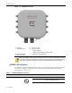
1 Introduction This chapter provides general information about the ExtremeWireless™ Outdoor Access Point AP3965. For information about... Refer to page... AP3965 Overview 1 AP3965 LED Indicators 2 Antennas 3 External Antenna Connectors 3 LAN Ports 3 AP Part Numbers 27 AP3965 Overview The AP3965 (see Figure 1‐1 on page 2) enables you to extend your wireless LAN beyond the boundaries of indoor locations. It is resistant to harsh outdoor conditions and extreme temperatures.
AP3965 Overview Figure 1-1 AP3965e Front View 1 AP Status 2 LAN 1 (Ethernet 1) 5 6 Radio 1 (5 GHz) LAN Ports (POE): • LAN 1 PDE Port 3 LAN 2 (Ethernet 2) 4 Radio 2 (2.4 GHz) 7 • LAN 2 PSE Port output of DC48V, 0.26A Console Port and Reset Button . Note: The AP3965e provides eight external antenna ports. The network administrator determines which antenna port will be used based on the external antenna selected.
AP3965 Overview Table 1-1 AP3965 LED Status Indicators (Continued) LED Indicator 2 (Ethernet link state) LAN 1 3 (Ethernet link state) LAN 2 4 (Radio 2 status) 5 (Radio 1 status) Status Description On Green Valid 100Mbps Ethernet link On Amber Valid 1Gbps Ethernet link Off Link down On Green Valid 100Mbps Ethernet link On Amber Valid 1Gbps Ethernet link Off Link down On Green Radio 2 enabled Off Radio 2 not on On Green Radio 1 enabled Off Radio 1 not on Antennas The AP3965i in
AP3965 Overview 4 Introduction
2 Installation This chapter provides installation instructions for the ExtremeWireless™ Outdoor Access Point AP3965. For information about... Refer to page... Unpacking the AP3965 5 Separately Ordered Components 6 AP3965 Installation Procedures 7 Weatherproofing the AP3965e Connections 17 Configuring AP3965 Channel Settings 19 Unpacking the AP3965 Unpack the AP3965 as follows: 1. Open the box and remove the packing material protecting the AP3965. 2.
Installation Separately Ordered Components Quantity Item 8 Screw assemblies, size M4, that include the screws, flat washers, and split washers. 1 Ground Screw assembly, size M4, that include the screw, star washer, and split washer. Optional: You may also need antennas, terminators, or cables. Refer to www.extremenetworks.com/support for product numbers. Note: Before mounting the AP3965, read the “RF Safety Distance” on page 46. 3.
AP3965 Installation Procedures Installation AP3965 Installation Procedures Use these instructions as guidelines for mounting and connecting the AP3965 easily and safely. The installation of the AP3965 should be performed by a professional installer to ensure proper operation and compliance with local safety guidelines. Attach the AP3965 to a surface that can support it and withstand its environment.
Installation AP3965 Installation Procedures Figure 2-1 AP3965 Ground Terminal Location Mounting the AP3965 to a Wall Mount the AP so that the glands are on the side of the AP closest to the ground, and not above the plastic cover. You must provide a 3‐inch drip loop on all cables. For more information, see “Forming a Drip Loop for AP3965e Cables” on page 19. 1. Using the mounting bracket as a guide, mark the location for the mounting screws on a horizontal, flat wall surface. 2.
AP3965 Installation Procedures Figure 2-2 Installation Mounting Bracket Orientation 3. Secure the anchors to the wall, then secure the bracket to the anchors. See Figure 2‐3 on page 10. 4. If using #10 screws, tighten them to a torque of 25 in‐lbs. If using ¼” screws, tighten them to 45 in‐lbs.
Installation AP3965 Installation Procedures Figure 2-3 Mounting the AP3965 to a Wall Note: Use anchors when mounting on cement walls. (Not shown above.) Mounting screws (shown above) are not included. Mounting the AP3965 to a Pole To fit the mounting plate to a pole: 1. Determine the diameter of the pole. Pole Diameter Cable Clamp Size <= 2.5” [63.5mm] Use small cable clamp. 6” - 7” (178mm) Use large cable clamp Note: For other pole diameters, provide your own stainless steel cable clamp.
AP3965 Installation Procedures Figure 2-4 5. Installation Attach Pole Bracket to “H” Bracket Attach the two cable clamp to the pole bracket. Open the cable clamp by turning a flat bladed screwdriver counterclockwise. Then, insert the non‐clamp end into the pole bracket through the holes. Note: It is easier to install both clamps before attaching to the pole.
Installation AP3965 Installation Procedures Figure 2-5 6. Put the metal band around the pole and insert it into the clamp. 7. Turn the clamp screw clockwise, tightening the band around the pole. 8. Secure the pole mount bracket to the AP mounting bracket using four M4 screws. 9. Secure the AP to the pole by tightening the stainless steel tie back strap (see Figure 2‐6).
AP3965 Installation Procedures Installation Attaching Antennas Install the external antennas intended for area coverage. For information about antenna selection and installation, refer to the ExtremeWireless™ External Antenna Site Preparation and Installation Guide. Notes: The total number of required antennas and associated port locations on the AP3965 depends on the coverage area and the type of antennas selected. To attach external antennas to the AP3965: 1.
Installation AP3965 Installation Procedures Figure 2-8 1 Sealing nut RJ45 Cable Gland Adapter Assembly 2 Claw 3 Seal 4 Main body Installing the Cable Gland Adapter Assembly Install the cable gland adapter assembly onto LAN 1 or LAN 2 as follows: 14 1. Insert the RJ45 cable onto the sealing nut. 2. Slide the claw and seal onto the RJ45 cable. 3. Plug the RJ45 cable into the port.
AP3965 Installation Procedures Installation Caution: Do not run the network cable through the cable conduit connector used for connecting the power cables. You must connect the network cable and power cables through separate connectors.
Installation 16 AP3965 Installation Procedures 4. Slide the seal and claw into the main body. 5. Secure the seal nut onto the main body. 6. Tighten the assembly by hand. Tighten the cap to 10 inch pounds.
Weatherproofing the AP3965e Connections Installation Weatherproofing the AP3965e Connections Extreme Networks recommends that all connections between the AP and antennas are weatherproofed using one of the following weatherproof kits (not supplied): • Wireless Weatherproofing Kits: – 3M (WK‐100) – Scotch (WK‐101) Each weatherproofing kit includes 3/4 inch vinyl tape, 2 inch mastic tape, and 2 inch vinyl tape. • Cold Shrink Kits: – 3M Cold Shrink Sealing Kit CXS (CXS‐4).
Installation Weatherproofing the AP3965e Connections Weatherproofing the Antenna The following guidelines should be followed to ensure proper installation: • The weatherproofing tape must be wound tightly over the connectors. • Care should be taken to ensure that no areas around the edges are exposed. Note: Installation instructions are provided with each weatherproofing kit and are included here for reference only. Figure 2‐9 shows how to wrap the antenna mounted directly to the AP3965e.
Configuring AP3965 Channel Settings Installation Forming a Drip Loop for AP3965e Cables Once the cables have been connected to the AP and the connections have been weatherproofed, gather each cable below the AP, and form a drip loop as shown in Figure 2‐10. Note: The drip loop prevents water from entering the AP by channeling water down and away from the connection points. Drip loops are required to ensure proper operation of the AP.
Installation Configuring AP3965 Channel Settings • Determine the Antenna Model • Configure Radio RF Port • Configure Radio Channel • Configure Radio Transmit (Tx) Power Determine the Antenna Model The professional installer needs to determine antenna models and the number of antenna ports for that model. The number of ports can be determined from visual inspection of the antenna or from the antenna model. For information about antenna models, see AP3965e, Table A‐3 on page 30.
Configuring AP3965 Channel Settings Figure 2-11 Installation AP Properties for the AP3965e ExtremeWireless™ AP3965 Installation Guide 21
Installation Configuring AP3965 Channel Settings 4. When configuring the AP3965e, click Professional Install. The Professional Install dialog displays to configure the external antennas. 5. Modify the Radio Antenna Type as follows: 6. 7. – If attaching quad port antennas, configure all four RF ports with the same antenna type. – If attaching triple port antennas, configure ports 1, 2, and 3 with the same antenna type and configure port 4 (non‐active port) to No Antenna.
Configuring AP3965 Channel Settings Installation 2. Click the Radio 1 tab. 3. Configure the desired Radio Mode, and Channel Width. Figure 2-12 4. AP3965e Radio 1 Properties: Base Settings From the Request a New Channel drop‐down menu, select a channel according to the site channel plan, or request the AP to auto select the channel from the channel list set in the Channel Plan setting.
Installation Configuring AP3965 Channel Settings Figure 2-13 5. AP3965e Radio 1 Properties: Channel Plan setting Repeat the process for Radio 2. Configure Radio Transmit (Tx) Power Based on the configured mode, channel, channel plan, and channel width for the specific antenna, the professional installer must enter the corresponding Transmit Power (Tx Power) for the desired Radio using the ExtremeWireless™ Assistant. 24 1. Log into the Wireless Assistant. 2. From the top menu, click AP.
Configuring AP3965 Channel Settings Figure 2-14 Installation AP3965e Radio 1 Properties: Max TX Power setting 6. The professional installer is responsible for accurately configuring port Attenuation. Port attenuation should never be configured higher than the actual attenuation between the AP port and the antenna. 7. Repeat the process for Radio 2.
Installation 26 Configuring AP3965 Channel Settings
A Specifications This appendix lists the specifications for the ExtremeWireless™ Outdoor Access Point AP3965. Table A-1 Specifications for the AP3965 Item Specification AP Part Numbers 31016 WS-AP3965I-FCC 31017 WS-AP3965I-ROW 31018 WS-AP3965E-FCC 31019 WS-AP3965E-ROW Enclosure material Metal enclosure IP67 rated Power source 802.3at or 802.3at+ compliant PoE Power consumption < 22W (Max.) when operating as AP only < 55W (Max.
Specifications Internal Antenna Access Points Internal Antenna Access Points The AP3965i is an indoor access with eight integrated internal antennas. The following specifications are for the internal antennas: Table A-2 AP3965i Internal Antennas Model Type Application Description Gain (dBi) Frequency (GHz Connector AP3965i Indoor MU-MIMO 5dBi 2.4 None 6dBi 5 None The following radiation patterns apply to the antennas in the AP3965i only.
Internal Antenna Access Points Specifications Vertical Radiation Pattern 2.
Specifications External Antennas Vertical Radiation Pattern 5 GHz External Antennas Table A‐3 lists the external antennas for AP3965e. For more detailed specifications and radiation pattern diagrams, see the ExtremeWireless™ External Antenna Site Preparation and Installation Guide. NOTE All antennas are for an outdoor application with Standard Polarity Type-N connectors. Table A-3 External Antennas for AP3965e Part No. (Short Description) 30 Frequency Band Antenna Type 2.
External Antennas Specifications Table A-3 External Antennas for AP3965e Part No. (Short Description) Frequency Band Antenna Type 2.4G Gain 5G Gain Shape 30715 (WS-AO-DE13025N)* 2.4G/5G Sector 13 11-12 25-degree, sector, eight-feed 30716 (WS-AO-5Q05025N) 5G Sector N/A 4.5-5 25-degree, sector, four-feed 30717 (WS-AO-5Q11025N) 5G Sector N/A 11-11.5 25-degree, sector, four-feed 30718 (WS-AO-DE10055N) 2.4G/5G Sector 10-10.5 6-7.
Specifications 32 External Antennas
B Regulatory Information This appendix provides regulatory information for the ExtremeWireless™ AP3965i and AP3965e. Warning Warnings identify essential information. Ignoring a warning can lead to problems with the application. NOTE Throughout this appendix, the term ExtremeWireless™ AP3965 refers to the AP models AP3965i and AP3965e. Specific AP models are identified in this appendix only where it is necessary to do so.
Regulatory Information AP3965 Warning Electrical Hazard: Only qualified personnel should perform installation procedures. Within the context of the safety notes in this documentation qualified persons are defined as persons who are authorized to commission, ground and label devices, systems and circuits in accordance with established safety practices and standards.
United States Regulatory Information EMC • FCC CFR 47 Part 15, Class B Radio transceiver • FCC CFR 47 Part 15.247, Subpart C (2.4 GHz) • FCC CFR 47 Part 15.407, Subpart E (5 GHz) Other • IEEE 802.11ac (5 GHz) • IEEE 802.11b/g (2.4 GHz) • IEEE 802.11n • IEEE 802.3at (PoE) • IEEE 802.
Regulatory Information Canada For a list of approved external antennas, see “External Antennas” on page 30. Professional Installation Notice To comply with FCC part 15 rules in the United States, the system must be professionally installed to ensure compliance with the Part 15 certification. It is the responsibility of the operator and professional installer to ensure that only certified systems are deployed in the United States.
Canada Regulatory Information The maximum antenna gain permitted for devices in the bands 5250‐5350 MHz and 5470‐5725 MHz shall be such that the equipment still complies with the e.i.r.p. limit. le gain maximal dʹantenne permis pour les dispositifs utilisant les bandes 5250‐5350 MHz et 5470‐ 5725 MHz doit se conformer à la limite de p.i.r.e. The maximum antenna gain permitted for devices in the band 5725‐5850 MHz shall be such that the equipment still complies with the e.i.r.p.
Regulatory Information European Community European Community . NOTE This product complies with the requirements of Directive 2011/65/EU of the European Parliament and of the Council of 8 June 2011 on the restriction of the use of certain hazardous substances in electrical and electronic equipment.
European Community Regulatory Information Par la présente, Extreme Networks déclare que ce Radio LAN device est conforme aux exigences essentielles et aux autres dispositions de la directive 1999/5/CE qui lui sont applicables. Swedish Härmed intygar Extreme Networks att denna Radio LAN device står I överensstämmelse med de väsentliga egenskapskrav och övriga relevanta bestämmelser som framgår av direktiv 1999/5/EG.
Regulatory Information European Community Safety • 2006/95/EC Low Voltage Directive (LVD) • IEC/EN 60950‐1 + National Deviations EMC (Emissions / Immunity) • 2004/108/EC EMC Directive • EN 55011/CISPR 11, Class B, Group 1 ISM • EN 55022/CISPR 22, Class B • EN 55024/CISPR 24, includes IEC/EN 61000‐4‐2,3,4,5,6,11 • EN 61000‐3‐2 and ‐3‐3 (Harmonics and Flicker) • EN 60601‐1‐2 (EMC immunity for medical equipment) • EN 50385 (EMF) • ETSI/EN 301 489‐1 & ‐17 Radio transceiver • R&TTE Direct
European Community Regulatory Information 2. When this product has reached the end of its serviceable life, it cannot be disposed of as unsorted municipal waste. It must be collected and treated separately. 3. It has been determined by the European Parliament that there are potential negative effects on the environment and human health as a result of the presence of hazardous substances in electrical and electronic equipment. 4.
Regulatory Information European Community CAUTION Follow the instructions in this guide to configure the ExtremeWireless™ AP3965. Each Wireless AP is configured with a default group of settings. There is the ability to change these settings. The user or installer is responsible to ensure that each AP3965 is configured properly. The software within the Wireless AP automatically limits the allowable channels and output power determined by the selected country code.
European Community Table B-1 Regulatory Information European Spectrum Usage Rules (Continued) Country 5.15-5.25 (GHz) Channels: 36,40,44,48 5.25-5.35 (GHz) Channels: 52,56,60,64 5.47-5.725 (GHz) Channels: 100,104,108,112,116, 132,136,140 2.4-2.4835 (GHz) Channels: 1 to 13 (Except Where Noted) Croatia Indoor only Indoor only Indoor or outdoor Indoor or outdoor Cyprus Indoor only Indoor only Indoor or outdoor Indoor or outdoor Czech Rep.
Regulatory Information Certifications of Other Countries NOTE Belgium requires notifying the spectrum agency if deploying > 300 meter wireless links in outdoor public areas. Certifications of Other Countries The AP3965i and AP3965e have been certified for use in various other countries. When the correct country code is selected, the Wireless AP automatically uses the proper frequencies and power outputs for that country code.
Certifications of Other Countries Regulatory Information ExtremeWireless™ AP3965 Installation Guide 45
Regulatory Information AP3965e Approved External Antennas NCC Statement AP3965e Approved External Antennas The AP3965e external antenna AP can be used with certified external antennas. However, in order to comply with the local laws and regulations, an approval may be required by the local regulatory authorities. The optional antennas have been tested and approved for use with the external antenna model.
Tables 1-1 2-1 A-1 A-2 A-3 B-1 AP3965 LED Status Indicators .............................................................................................................. 2 Contents of the AP3965 Carton............................................................................................................. 5 Specifications for the AP3965 ............................................................................................................. 27 AP3965i Internal Antennas.............................
48
Figures 1-1 2-1 2-2 2-3 2-4 2-5 2-6 2-7 2-8 2-9 2-10 2-11 2-12 2-13 2-14 AP3965e Front View.............................................................................................................................. 2 AP3965 Ground Terminal Location ....................................................................................................... 8 Mounting Bracket Orientation ................................................................................................................
50