ExtremeWireless™ WSAP3865e Installation Guide P/N 9034808-02 March 2017
Copyright © 2017 Extreme Networks, Inc. All Rights Reserved. Legal Notices Extreme Networks, Inc., on behalf of or through its wholly-owned subsidiary, Enterasys Networks, Inc., reserves the right to make changes in specifications and other information contained in this document and its website without prior notice. The reader should in all cases consult representatives of Extreme Networks to determine whether any such changes have been made.
Hazardous Substances This product complies with the requirements of Directive 2011/65/EU of the European Parliament and of the Council of 8 June 2011 on the restriction of the use of certain hazardous substances in electrical and electronic equipment. European Waste Electrical and Electronic Equipment (WEEE) Notice In accordance with Directive 2011/65/EU of the European Parliament on waste electrical and electronic equipment (WEEE): 1.
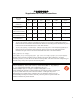
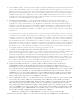
ѻક䇈ᯢк䰘ӊ Supplement to Product Instructions 䚼ӊৡ⿄ (Parts) 䞥ሲ䚼ӊ (Metal Parts) ⬉䏃ഫ (Circuit Modules) ⬉㓚ঞ⬉㓚㒘ӊ (Cables & Cable Assemblies) ล᭭㘮ড়⠽䚼ӊ (Plastic and Polymeric parts) ⬉䏃ᓔ݇ (Circuit Breakers) ƻ˖ 䪙 3E ᳝↦᳝ᆇ⠽䋼ܗ㋴ (Hazardous Substance) ⒈㘨㣃 ∲ 䬝 ݁Ӌ䫀 3%% +J &G &U h ƻ ƻ ƻ ƻ ƻ h ƻ ƻ ƻ ƻ ƻ h ƻ ƻ ƻ ƻ ƻ ƻ ƻ ƻ ƻ ƻ ƻ ƻ ƻ ƻ ƻ ƻ ƻ ⒈Ѡ㣃䝮 3%'( 㸼⼎䆹᳝↦᳝ᆇ⠽䋼䆹䚼ӊ᠔᳝ഛ䋼ᴤ᭭Ёⱘ䞣ഛ SJ/T 11363-2006 ᷛޚ㾘ᅮⱘ䰤䞣㽕∖ҹϟDŽ Indicates that the concentration of the hazardous substance
Enterasys Networks, Inc. Firmware License Agreement BEFORE OPENING OR UTILIZING THE ENCLOSED PRODUCT, CAREFULLY READ THIS LICENSE AGREEMENT. This document is an agreement ("Agreement") between the end user ("You") and Enterasys Networks, Inc., a wholly-owned subsidiary of Extreme Networks, Inc.
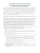
3. APPLICABLE LAW. This Agreement shall be interpreted and governed under the laws and in the state and federal courts of the State of California without regard to its conflicts of laws provisions. You accept the personal jurisdiction and venue of the Superior Court of California in Santa Clara County or the United States District Court for the Northern District of California in San Jose, California.
TORT OR OTHERWISE, SHALL NOT EXCEED THE TOTAL AMOUNT OF FEES PAID TO ENTERASYS BY YOU FOR THE RIGHTS GRANTED HEREIN. 8. AUDIT RIGHTS. You hereby acknowledge that the intellectual property rights associated with the Program are of critical value to Enterasys and its Affiliates, and, accordingly, You hereby agree to maintain complete books, records and accounts showing: (i) license fees due and paid, and (ii) the use, copying and deployment of the Program.
13. WAIVER. A waiver by Enterasys of a breach of any of the terms and conditions of this Agreement must be in writing and will not be construed as a waiver of any subsequent breach of such term or condition. Enterasys’ failure to enforce a term upon Your breach of such term shall not be construed as a waiver of Your breach or prevent enforcement on any other occasion. 14. SEVERABILITY.
viii
Contents About This Guide Who Should Use This Guide .............................................................................................................................xi How to Use This Guide ......................................................................................................................................xi Related Documents ..........................................................................................................................................
European Spectrum Usage Rules ..................................................................................................... B-9 Certifications of Other Countries ..................................................................................................................B-10 WS-AP3865e Approved External Antennas ...........................................................................................B-11 Tables 1-1 2-1 A-1 B-1 B-2 WS-AP3865e LED Status Indicators ...........................
About This Guide The guide describes how to mount and connect cables to the IdentiFi Wireless Outdoor Access Point WS‐AP3865e. In addition, this guide provides information on the product certifications and national approvals for the WS‐AP3865e. Note: This guide does not provide information on configuration of the WS-AP3865e. For information on how to configure the WS-AP3865e, see the IdentiFi Wireless Software User Guide.
Related Documents Related Documents The manuals listed below can be obtained from the World Wide Web in Adobe Acrobat Portable Document Format (PDF) at the following site: https://extranet.enterasys.com/downloads/ • IdentiFi Wireless AP External Antenna Site Preparation and Installation Guide • IdentiFi Wireless Software User Guide Typographical Conventions The following typographical conventions and icons are used in this document. blue type Indicates a hypertext link.
1 Introduction This chapter provides general information about the IdentiFi Wireless Outdoor Access Point WS‐ AP3865e. For information about... Refer to page... WS-AP3865e Overview 1-1 WS-AP3865e LED Indicators 1-3 Antennas 1-4 External Antenna Connectors 1-4 LAN Ports 1-4 WS-AP3865e Overview The WS‐AP3865e (see Figure 1‐1 on page 1‐2) enables you to extend your wireless LAN beyond the boundaries of indoor locations. They are resistant to harsh outdoor conditions and extreme temperatures.
WS-AP3865e Overview Figure 1-1 WS-AP3865e Front View The following view (see Figure 1‐2) illustrate the connections to the WS‐AP3865e. Figure 1-2 1 2 3 4 WS-AP3865e Top/Bottom View Radio 2 - Left Antenna (2.4 GHz) Radio 1 - Middle Antenna (5.0 GHz) Radio 2 - Right Antenna (2.4 GHz) Radio 1 - Left Antenna (5.0 GHz) 5 6 7 8 LAN 1 Port (POE Input) Radio 2 - Middle Antenna (2.4 GHz) LAN 2 Port (Pwr Out) Radio 1 - Right Antenna (5.0 GHz) Note: The WS-AP3865e provides six external antenna ports.
WS-AP3865e Overview WS-AP3865e LED Indicators The WS‐AP3865e provides four LED indicators (see Figure 1‐2). The LEDs provide status information (see Table 1‐1 on page 1‐3) on the current state of the WS‐AP3865e. For more information, see the IdentiFi Wireless Software User Guide. Figure 1-3 Table 1-1 WS-AP3865e LEDs WS-AP3865e LED Status Indicators LED Status Description 1 (Radio 1 status) On Green Indicates Radio 1 is enabled. Off Indicates Radio 1 is not on.
WS-AP3865e Overview Antennas The WS‐AP3865e includes external antennas for wireless communications. The WS‐AP3865e can transmit from multiple antennas at the same time, as defined with MIMO operation, but the antennas must be selected manually based on customer requirements and coverage area. For a list of external antennas, refer to Appendix B, WS‐AP3865e Approved External Antennas. External Antenna Connectors The WS‐AP3865e supports six external antenna connections for both 2.4GHz and 5GHz radios.
2 Installation This chapter provides installation instructions for the IdentiFi Wireless Outdoor Access Point WS‐AP3865e. For information about... Refer to page... Package Contents 2-1 Separately Ordered Components 2-2 WS-AP3865e Installation Procedures 2-2 Weatherproofing the AP3865e Connections 2-12 Ground Connection 2-15 Package Contents The WS‐AP3865e package includes components necessary for installation. Unpacking the WS-AP3865e Unpack the WS‐AP3865e as follows: 1.
Installation Separately Ordered Components Table 2-1 WS-AP3865e Supplied Components (Continued) Quantity 1 3. Item WS-AP3865e Quick Reference Perform a visual inspection of the WS‐AP3865e for any signs of physical damage. Contact Extreme Networks if there are any signs of damage. Separately Ordered Components The following list of accessories are available for the IdentiFi Wireless Access Point WS‐AP3865e. For ordering information, contact your Extreme Networks sales representative. • Antennas.
WS-AP3865e Installation Procedures Installation • Attaching the Mounting Bracket to the AP • Mounting the WS‐AP3865e to a Wall • Mounting the WS‐AP3865e to a Pole • Attaching Antennas • LAN 1/LAN 2 Connections • Ground Connection Removing the AP Cover If desired, remove the AP cover for custom painting. Note: The cover must be painted and reinstalled prior to installing the AP mounting bracket 1. Remove the four mounting screws as shown in Figure 3. 2.
Installation WS-AP3865e Installation Procedures Attaching the Mounting Bracket to the AP To attach the mounting bracket to the WS‐AP3865e: 1. Determine the desired orientation (vertical or horizontal) of the mounting bracket (see Figure 2‐2 on page 2‐4). 2. Attach the mounting bracket to the WS‐AP3865e using four M4 screws, four spring washers, and four flat washers. 3. Tighten the four screws to a torque of 12.0 in‐lbs.
WS-AP3865e Installation Procedures Figure 2-3 Installation Mounting the WS-AP3865e to a Wall Mounting the WS-AP3865e to a Pole To fit the mounting plate to a pole: 1. Position the pole mount bracket (see item 1, Figure 2‐4) onto the AP mounting bracket in either the horizontal or vertical position.
Installation WS-AP3865e Installation Procedures Figure 2-4 Pole Mount Orientation Horizontal Pole Orientation 2-6 Vertical Pole Orientation 2. Secure the pole mount bracket to the AP mounting bracket using four M4 screws. 3. Tighten the four screws to a torque of 12.0 in‐lbs. 4. Secure the AP to the pole by tightening the stainless steel tie back strap (see Figure 2‐5).
WS-AP3865e Installation Procedures Figure 2-5 Installation .WS-AP3865e Pole Mount Option - Vertical Position Attaching Antennas Notes: The total number of required antennas and associated port locations on the WS-AP3865e is dependant on the coverage area and the type of antennas selected. To attach external antennas to the WS‐AP3865e: 1.
Installation WS-AP3865e Installation Procedures Figure 2-6 1 Installing Terminator Caps Terminator cap 2 Antenna connector LAN 1/LAN 2 Connections The WS‐AP3865e has two LAN ports (LAN 1 and LAN 2). Refer to Figure 1‐2 on page 1‐2 for the location of these ports. Before connecting an RJ45 cable (not provided) to either port, a waterproof cable gland adapter assembly must be installed onto the cable (see Figure 2‐7).
WS-AP3865e Installation Procedures Installation 2. Slide the claw and seal onto the RJ45 cable. 3. Screw the main body into the port of the WS‐AP3865e. 1 Main body 4. Plug the RJ45 cable into the port.
Installation WS-AP3865e Installation Procedures Caution: Do not run the network cable through the cable conduit connector used for connecting the power cables. You must connect the network cable and power cables through separate connectors.
WS-AP3865e Installation Procedures Installation 5. Slide the seal and claw into the main body. 6. Secure the seal nut onto the main body. 7. Tighten the assembly by hand.Tighten the cap to 10 inch‐pounds (shown below).
Installation Weatherproofing the AP3865e Connections Weatherproofing the AP3865e Connections Extreme Networks recommends that all connections between the AP and antennas are weatherproofed using one of the following weatherproof kits (not supplied): • Wireless Weatherproofing Kits: – 3M (WK‐100) – Scotch (WK‐101) Each weatherproofing kit includes 3/4 inch vinyl tape, 2 inch mastic tape, and 2 inch vinyl tape. • Cold Shrink Kits: – 3M Cold Shrink Sealing Kit CXS (CXS‐4).
Weatherproofing the AP3865e Connections Installation Weatherproofing the Antenna The following guidelines should be followed to ensure proper installation: • The weatherproofing tape must be wound tightly over the connectors. • Care should be taken to ensure that no areas around the edges are exposed. Note: Installation instructions are provided with each Weatherproofing Kit and are included here for reference only. Figure 2‐8 shows how to wrap the antenna mounted directly to the AP3865e.
Installation Weatherproofing the AP3865e Connections Forming a Drip Loop for AP3865e Cables Once the cables have been connected to the AP and the connections have been weatherproofed, gather each cable below the AP, and form a drip loop as show in Figure 2‐9. Note: The drip loop prevents water from entering the AP by channeling water down and away from the connection points. Drip loops are required to ensure proper operation of the AP.
Ground Connection Installation Ground Connection 1. The ground connection for the WS‐AP3865e is located on the rear of the device. Attach a ground to earth cable to the grounding terminal (see Figure 2‐10) using one ground screw. 2. Tighten the screw to a torque of 12.0 in‐lbs.
Installation 2-16 Ground Connection
A Specifications This appendix lists the specifications for the IdentiFi Wireless Outdoor Access Point WS‐AP3865e. Table A-1 Specifications for the WS-AP3865e Item Specification Enclosure material Metal enclosure IP67 rated Power source 802.3at compliant PoE Power consumption < 40W (Max.) Antenna 6x RP-N Jack antenna connectors; 2.4GHz x 3, 5GHz x 3, 6x antenna terminator caps Uplink Interface GbE Ethernet x1 with PoE RoHS compliant Yes Radio Configuration IEEE 802.11a/b/g/n, 2.
A-2 Specifications
B Regulatory Information Warning: Warnings identify essential information. Ignoring a warning can lead to problems with the application. This appendix provides regulatory information for the WS‐AP3865e. Notes: Specific AP models are only identified in this appendix where it is necessary to do so. Warning: Changes or modifications made to the WS-AP3865es which are not expressly approved by Extreme Networks could void the user's authority to operate the equipment.
WS-AP3865e • This device must accept any interference received, including interference that may cause undesired operation. This equipment has been tested and found to comply with the limits for a Class B digital device, pursuant to Part 15 of the FCC Rules. These limits are designed to provide reasonable protection against harmful interference when the equipment is operated in a residential and business environment.
WS-AP3865e FCC RF Radiation Exposure Statement The WS‐AP3865e complies with FCC RF radiated exposure limits set forth for an uncontrolled environment. End users must follow the specific operating instructions for satisfying RF exposure compliance. This device has been tested and has demonstrated compliance when simultaneously operated in the 2.4 GHz and 5 GHz frequency ranges. This device must not be co‐located or operated in conjunction with any other antenna or transmitter.
WS-AP3865e • Operation in the 5150‐5250 MHz band is only for indoor usage to reduce potential for harmful interference to co‐channel mobile satellite systems. • Please note that high power radars are allocated as primary users (meaning they have priority) and can cause interference in the 5250‐5350 MHz and 5470‐5725 MHz bands of LE‐ LAN devices. • For the product available in the Canadian market, only channels 1 to 11 can be operated. Selection of other channels in the 2.4 GHz band is not possible.
WS-AP3865e Declaration of Conformity with R&TTE Directive of the European Union 1999/5/EC The following symbol indicates compliance with the Essential Requirements of the R&TTE Directive of the European Union (1999/5/EC).
WS-AP3865e Declaration of Conformity in Languages of the European Community English Hereby, Extreme Networks, declares that this Radio LAN device is in compliance with the essential requirements and other relevant provisions of Directive 1999/5/EC. Finnish Valmistaja Extreme Networks vakuuttaa täten että Radio LAN device tyyppinen laite on direktiivin 1999/5/EY oleellisten vaatimusten ja sitä koskevien direktiivin muiden ehtojen mukainen.
WS-AP3865e Czech Extreme Networks tímto prohlašuje, že tento Radio LAN device je ve shodě se základními požadavky a dalšími příslušnými ustanoveními směrnice 1999/5/ES." Slovenian Šiuo Extreme Networks deklaruoja, kad šis Radio LAN device atitinka esminius reikalavimus ir kitas 1999/5/EB Direktyvos nuostatas.
WS-AP3865e RoHS • European Directive 2002/95/EC External Antennas The external antennas used with the WS‐AP3865e must be approved and certified before use. However, in order to comply with the local laws and regulations, an approval may be required by the local regulatory authorities. For a list of approved external antennas, see “WS‐AP3865e Approved External Antennas” on page B‐11.
WS-AP3865e European Spectrum Usage Rules The AP configured with approved internal or external antennas can be used for indoor and outdoor transmissions throughout the European community as displayed in Table B‐1. Some restrictions apply in Belgium, France, Greece, and Italy. Table B-1 European Spectrum Usage Rules Country 5.15-5.25 (GHz) Channels: 36,40,44,48 5.25-5.35 (GHz) Channels: 52,56,60,64 5.47-5.725 (GHz) Channels: 100,104,108,112,116, 132,136,140 2.4-2.
Certifications of Other Countries Table B-1 European Spectrum Usage Rules (continued) Country 5.15-5.25 (GHz) Channels: 36,40,44,48 5.25-5.35 (GHz) Channels: 52,56,60,64 5.47-5.725 (GHz) Channels: 100,104,108,112,116, 132,136,140 2.4-2.
Certifications of Other Countries WS-AP3865e Approved External Antennas The WS‐AP3865e external antenna AP can be used with certified external antennas. However, in order to comply with the local laws and regulations, an approval may be required by the local regulatory authorities. The optional antennas listed in Table B‐2 have been tested and approved for use with the external antenna model.
Certifications of Other Countries B-12 Regulatory Information
Figures 1-1 1-2 1-3 2-1 2-2 2-3 2-4 2-5 2-6 2-7 2-8 2-9 2-10 WS-AP3865e Front View.................................................................................................................... 1-2 WS-AP3865e Top/Bottom View ......................................................................................................... 1-2 WS-AP3865e LEDs ............................................................................................................................ 1-3 AP Cover .................
1-2
Tables 1-1 2-1 A-1 B-1 B-2 WS-AP3865e LED Status Indicators .................................................................................................. 1-3 WS-AP3865e Supplied Components ................................................................................................. 2-1 Specifications for the WS-AP3865e ...................................................................................................A-1 European Spectrum Usage Rules ................................................
1-2