™ ExtremeMobility AP505i FCC/WR Installation Guide 9035992-01 Rev AA Published July 2019
Copyright © 2019 Extreme Networks, Inc. All rights reserved. Legal Notice Extreme Networks, Inc. reserves the right to make changes in specifications and other information contained in this document and its website without prior notice. The reader should in all cases consult representatives of Extreme Networks to determine whether any such changes have been made. The hardware, firmware, software or any specifications described or referred to in this document are subject to change without notice.
Table of Contents Preface......................................................................................................................................... 4 Text Conventions...................................................................................................................................................................4 Platform-Dependent Conventions................................................................................................................................
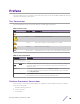
Preface This section discusses the conventions used in this guide, ways to provide feedback, additional help, and other Extreme Networks® publications. Text Conventions The following tables list text conventions that are used throughout this guide. Table 1: Notice Icons Icon New! Notice Type Alerts you to... General Notice Helpful tips and notices for using the product. Note Important features or instructions. Caution Risk of personal injury, system damage, or loss of data.
Preface When a feature or feature implementation applies to specific platforms, the specific platform is noted in the heading for the section describing that implementation in the ExtremeXOS command documentation (see the Extreme Documentation page at www.extremenetworks.com/ documentation/). In many cases, although the command is available on all platforms, each platform uses specific keywords.
Preface • • • Network load at the time of trouble (if known) The device history (for example, if you have returned the device before, or if this is a recurring problem) Any related RMA (Return Material Authorization) numbers Subscribing to Service Notifications You can subscribe to email notifications for product and software release announcements, Vulnerability Notices, and Service Notifications. 1 Go to www.extremenetworks.com/support/service-notification-form.
1 Overview LED Indicators Powering Methods The AP505i is a next generation, indoor ceiling mount model enterprise-class 802.11ax access point (AP). The “i” in AP505i indicates that it comes with internal antennas. The AP features two simultaneous 4 x 4 radios, eight WiFi internal antennas, and one Bluetooth Low Energy (BLE) antenna. The AP505i can be mounted on a dry or wood wall, solid-flat ceiling, junction/ gang box, and on a suspended or drop ceiling.
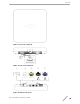
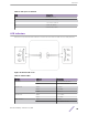
Overview Figure 1: Top view of AP505i Figure 2: Side view of AP505i Figure 3: AP505i side ports ExtremeMobility™ AP505i FCC/WR 8
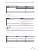
Overview Table 3: Side ports on AP505i Item Description 1 Kensington Lock 2 12V DC Power Supply 3 Console Port (Yellow) 4 LAN2 (GE) (Black) 5 LAN1 (5GE) (Purple) LED Indicators AP505i access points have LED indicators on the front of the unit. The LEDs are not visibly marked. Figure 4: AP505i LED Icons Table 4: AP505i LEDs LED Icon LED Color Description AP Status Green Normal operational status Amber Non-operational status Amber 100 Mbps Green 1000 Mbps Purple 2.
Overview Table 4: AP505i LEDs (continued) LED Icon LED Color Description Radio #2 Status Green 5 GHz Amber 5 GHz Off Non-operational status Blue Indicates BLE is enabled Off Non-operational status IoT (BLE) Powering Methods Table 5: AP505i Powering Methods Power Source Description Power over Ethernet (PoE) Power is provided through the RJ45 Ethernet port (GE1 port) to the right of the 12V DC port of AP505i, compliant to be powered by 802.3af and 802.3at.
2 Installation Process Verifying the Box Contents Mounting Brackets and Accessories Usage Mounting to a Suspended/Drop Ceiling Mounting the AP on a Dry or Wood Wall/Solid Flat Ceiling Mounting to a Junction/Gang box Mounting the AP to a Beam Connecting the Power Supply Follow this procedure to install AP505i: 1 Verify the box contents. 2 Review the Safety Guidelines. 3 Mount the AP to a flat ceiling. Alternatively, you can also mount the AP to a junction/gang box, or a suspended or drop ceiling.
Installation Process 2 Perform a visual inspection of the AP for any signs of physical damage. Contact Extreme Networks if there are any signs of damage. Note Before mounting the AP505i, read the Safety Guidelines. Mounting Brackets and Accessories Usage The access point comes with the Main Mounting Bracket (#37201) and the M3 security screw kit. The AP can also be used with various other brackets and accessories that can be purchased separately.
Installation Process Table 10: Brackets and accessories usage for various installation options Mounting Wall bracket install or accessory Solid flat ceiling install Ceiling Ceiling Junction install (T- install box bar) (protrude install d T-bar) Beam install 37201; Yes main mounting bracket Yes Yes Yes, by No adding the optional T-bar adapter to the main mounting bracket KT-13562 No 8-01 accessory ; used with main mounting bracket No Yes Yes 30518 No WS-MBIDCMTR01 bracket No Yes 30516 WS-MBI
Installation Process Table 10: Brackets and accessories usage for various installation options (continued) Mounting Wall bracket install or accessory Solid flat ceiling install Ceiling Ceiling Junction install (T- install box bar) (protrude install d T-bar) Beam install Ceiling tile protrusio n T-bar widths Notes 37210 flat Yes metal easyattach adapter; used with main mounting bracket Yes No No No No No N/A Wall mount, ceiling mount, or install on any solid surface.
Installation Process Mounting the AP using the Main Mounting Bracket to a Flat T-bar The AP can be mounted on a t-bar using the main mounting bracket that is shipped with the unit. The mounting bracket does not come attached to the unit. Pre-Installation Checklist: • T-bar maximum base thickness: 0.055”. • T-bar bottom must be flat all the way across. • T-bar minimum base thickness: N/A; must be structurally sound. • T-bar width must be 15/16” (24mm). • Ceiling tile must be flat all the way across.
Installation Process 3 Hold the AP and rock it back and forth to ensure it is securely mounted. 4 Replace the tiles. 5 Attach the Ethernet cable's RJ45 connector to the LAN1 port. Mounting the AP using the Main Mounting Bracket and KT-135628-01 Adapter to a Flat T-bar Mounting the AP to a suspended or drop ceiling requires the optional adaptor (Universal Mounting Kit for WLAN APs; # KT- 135628-01). The adapter requires a flat t-bar and fits a ceiling tile with up to a 0.35” protrusion from the bar.
Installation Process 4 Hold the AP and rock it back and forth to ensure that it is securely mounted. 5 Attach the Ethernet cable’s RJ45 connector to the LAN1 port. Mounting the AP using the WS-MBI-DCFLUSH Bracket to a Flat T-bar The optional WS-MBI-DCFLUSH (#37211) bracket can also be used for T-bar installations without the mounting bracket. Pre-Installation checklist: • T-bar width must be 9/16” (15mm), 15/16” (24mm), 1.5” (38mm).T-bar bottom must be flat all the way across.
Installation Process 5 Slide the T-bar ceiling mount bracket base into the back of the access point. The locking tab fits into a groove in the outside of the AP. Figure 7: Attaching the AP unit onto the WS-MBI-DCFLUSH bracket 6 Hold the AP and rock it back and forth to ensure that it is securely mounted. 7 Attach the Ethernet cable’s RJ45 connector to the LAN1 port and place the ceiling tile back in place.
Installation Process 2 Open the movable sliding part of the T-bar to give the stationary and slider T-bar more space. 3 Hook the stationary end of the T-bar bracket onto the T-bar. 4 Tilt the T-bar up slightly in such a way that you are holding the stationary and movable sides of the bracket. 5 Squeeze the bracket parts together until you hear the T-bar locking tab click into place. 6 Slide the T-bar ceiling mount bracket base into the back of the access point.
Installation Process Mounting the AP on a Dry or Wood Wall/Solid Flat Ceiling The AP505i can be mounted to a dry/wood wall or a solid flat ceiling using various mounting brackets listed in this section. Note The recommended method of installation is using the Main Mounting Bracket. Pre-Installation checklist: • The mounting surface, item, and hardware must be able to support the AP in all environmental conditions. • The mounting surface should be flat.
Installation Process 4 Insert the AP onto the bracket’s four feet and slide it to the right to lock it in place. Figure 9: Attaching the access point to the main mounting bracket Label Description 1 Guide posts to attach the security torx locking screw 5 Attach the security torx locking screw to keep the main mounting bracket in place. For more information, see Install a Security Torx Locking Screw on page 22.
Installation Process Install a Security Torx Locking Screw The security torx locking screw is used to prevent the access point from being removed from the main mounting bracket (#37201). There are two security lock screw holes on the rear of the access point. Follow this procedure to install the security torx locking screw using one of the security lock holes on the access point. Note Perform this task after the access point is attached to the main mounting bracket on a dry or wood wall.
Installation Process Mounting the AP to a wall using the WS-MBI-WALL04 bracket Mounting the AP to a flat ceiling requires the WS-MBI-WALL04 (#30516) bracket, two Philips Pan-head screws, and two screw-in anchors. They must be purchases separately. 1 Install the WS-MBI-WALL04 bracket on a wall/ceiling with the two screws and screw-in anchors. Ensure that the locking tab on the WS-MBI-WALL04 bracket is on the top side during installation.
Installation Process Figure 12: Mounting the AP using the WS-MBI-WALL04 Bracket (when bracket corners are broken off) 2 Connect the LAN cable to the AP. 3 Insert the AP onto the keyhole posts and slide the AP. 4 Lock the AP into place at about 1/4 inch. Mounting the AP onto a wall using the Main Bracket and the Flat Metal EasyAttach adapter The AP can also be mounted onto a wall or solid ceiling by attaching a flat metal easy-attach adaptor to the main mounting bracket.
Installation Process 5 Hold the AP, insert and tighten the 2 screws until you lock it into place. Note The “E” logo must be in the right orientation before tightening the screws. Mounting to a wall using the Philips Pan-head screws You can mount the AP505i access point directly onto a dry/solid wall using the Philips Pan-Head screws. This is an optional installation method and not the preferred mode of installation. 1 Drill two holes 104 mm (4.
Installation Process 4 Align the AP against the screw heads and slide it down. Ensure that the AP is secured in place and tightened. If the AP is loose, unmount the AP and decrease the distance between the screw head and the wall. Remount the AP. Note When installing the AP, the “E” logo should be in the right orientation.
Installation Process • • The AP505i access point can be mounted onto a beam using a beam clip accessory (BRKT-000147A-01) to the main mounting bracket. The beam should be flat. Before attaching the AP onto a beam, verify that: • Beam attachment area is at least 0.5” (12.7mm) wide and as long as the AP’s largest dimension. • Beam mounting surface is less than 0.650” (16.5mm) thick.
Installation Process 2 The AP505i can also be powered by an external DC power supply plugged into an AC source. Plug the supply’s input jack into the DC-In port. Table 11: AP505i Power Supply Options AP505i Port Function LAN1 Port 12V DC Power Supply Note PoE is disabled when external power supply is used.
3 Specifications This section lists the specifications for the ExtremeMobility™ Indoor Access Point AP505i. AP505i Specifications Table 12: Physical Specifications Part Number: AP505i-FCC Cloud-ready, Dual Radio 802.11ax/ac/abgn, 4 x 4:4 MIMO Indoor 11ax access point. Internal Antenna. Domain: US, Puerto Rico, and Colombia Part Number: AP505i-WR Cloud-ready, Dual Radio 802.11ax/ac/abgn, 4 x 4:4 MIMO Indoor 11ax access point. Internal Antenna. Domain: EMEA and Rest of the World Dimensions 8.26" x 8.
4 Regulatory Information Federal Communications Commission (FCC) Notice Industry Canada Notice Brazil Anatel Statement Hazardous Substances Supplement to Product Instructions NCC Statement Indoor Use Only CE Information European Waste Electrical and Electronic Equipment (WEEE) Notice Declaration of Conformity in Languages of the European Community Federal Communications Commission (FCC) Notice This equipment has been tested and found to comply with the limits for a Class B digital device, pursuant to Part
Regulatory Information Operations in the 5.15-5.25GHz band are restricted to indoor usage only. Warning FCC Radiation Exposure Statement:This equipment complies with FCC radiation exposure limits set forth for an uncontrolled environment. This equipment should be installed and operated with minimum distance 23cm between the radiator & your body. Industry Canada Notice This device complies with ISED’s licence-exempt RSSs.
Regulatory Information Insert a section title Insert content for the first section. Brazil Anatel Statement Este produto está homologado pela ANATEL, de acordo com os procedimentos regulamentados pela Resolução n°. 242/2000 e atende aos requisitos técnicos aplicados. Este equipamento não tem direito à proteção contra interferência prejudicial e não pode causar interferência em sistemas devidamente autorizados. Para maiores informações, consulte o site da ANATEL – www.anatel.gov.
Regulatory Information NCC Statement Indoor Use Only Warning Indoor use only. この製品は屋内においてのみ使用可能です CE Information Warning MPE Radiation Exposure Statement: This equipment complies with EU radiation exposure limits set forth for an uncontrolled environment. This equipment should be installed and operated with minimum distance 20cm between the radiator and your body. The device is restricted to indoor use only when operating in the 5150 to 5350 MHz frequency range.
Regulatory Information The frequency and the maximum transmitted power in EU are listed below: • 2412-2472MHz: 19.99 dBm • 2402-2480MHz (LE): 7.56 dBm • 5180-5240MHz: 22.99 dBm • 5260-5320MHz: 22.99 dBm • 5500-5700MHz: 22.99 dBm • 2405-2480MHz: 5.
Regulatory Information Dutch Hierbij verklaart Extreme Networks dat het toestel Radio LAN device (AP505i) in overeenstemming is met de essentiële eisen en de andere relevante bepalingen van richtlijn 2014/53/EU. French Par la présente Extreme Networks déclare que l'appareil Radio LAN device (AP505i) est conforme aux exigences essentielles et aux autres dispositions pertinentes de la directive 2014/53/EU.
A Antenna Information Internal Antenna access point The AP505i is an indoor access point with eight WiFi internal antennas and one BLE internal antenna. Table 15: AP505i Internal Antenna Access point model Application Description Gain (dBi) Frequency (GHz) Connector AP505i Indoor MIMO 4 dBi 2.
Antenna Information Antenna Patterns - 2.4 GHz Figure 14: Horizontal Radiation Pattern 2.
Antenna Information Figure 15: Vertical Radiation Pattern 2.
Antenna Information Antenna Patterns - 5 GHz Figure 16: Horizontal Radiation Pattern 5 GHz ExtremeMobility™ AP505i FCC/WR 39
Antenna Information Figure 17: Vertical Radiation Pattern 5 GHz ExtremeMobility™ AP505i FCC/WR 40
Index A AP505i, Antenna Specifications, Antenna Patterns 36, 37, 39 AP505i, AP505i brackets, AP505i accessories, brackets usage, accessories usage 12 AP505i, Beam Mounting, Mounting Procedure 26 AP505i, Box Contents, Contents, AP505i Box 11 AP505i, Industry Canada Notice 31, 32 AP505i, Installation Process, AP505i Installation 11 AP505i, LED Indicators 9 AP505i, Mounting procedure, mounting bracket, mounting, wall mounting 20 AP505i, Mounting Procedure, Wall Mounting, Dry Wall Mounting 20 AP505i, Mounting P