Avaya Switch Clustering Virtual Services Platform Ethernet Routing Switch Engineering > Switch Clustering Supported Topologies and Interoperability with Virtual Services Platform 9000 & Ethernet Routing Switches Avaya Data Solutions Document Date: July 2011 Document Number: NN48500-555 Document Version: 1.
avaya.com © 2011 Avaya Inc. All Rights Reserved. Notices While reasonable efforts have been made to ensure that the information in this document is complete and accurate at the time of printing, Avaya assumes no liability for any errors. Avaya reserves the right to make changes and corrections to the information in this document without the obligation to notify any person or organization of such changes.
avaya.com Abstract This document is intended to show the various supported topologies and features for switch clustering on the Virtual Services Platform 9000 and Ethernet Routing Switch portfolio. With each topology, please take note to where bridging, routing, and multicast are configured as support will vary between switch types.
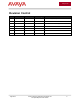
avaya.com Revision Control No Date Version Revised By Remarks 1 July 2008 1.2 D. DeBacker Various Changes & Updates 2 March 2011 1.3 K. Marshall Added VSP 9000 3 June 2011 1.4 K. Marshall Added ERS 5000 Mesh Support 4 July 2011 1.5 K.
avaya.com Table of Contents Figures .......................................................................................................................................................... 6 Tables............................................................................................................................................................ 7 1. Overview ............................................................................................................................................
avaya.com Figures Figure 3.1 – Triangle Layer 2 Core & Edge ................................................................................................ 10 Figure 3.2 – Triangle Layer 3 Core (VRRP) & Layer 2 Edge...................................................................... 11 Figure 3.3 – Triangle Layer 3 Core (RSMLT) & Layer 2 Edge ................................................................... 12 Figure 3.4 – Triangle Layer 3 Core (RSMLT) & Layer 3 Edge ..................................
avaya.com Tables Table 2.0 – Platforms / Software Releases................................................................................................... 9 Table 3.1 – Triangle Layer 2 Core & Edge ................................................................................................. 10 Table 3.2 – Triangle Layer 3 Core (VRRP) & Layer 2 Edge ....................................................................... 11 Table 3.3 – Triangle Layer 3 Core (RSMLT) & Layer 2 Edge .....................
avaya.com Conventions This section describes the text, image, and command conventions used in this document. Symbols Tip – Highlights a configuration or technical tip. Note – Highlights important information to the reader. Warning – Highlights important information about an action that may result in equipment damage, configuration or data loss. Text Bold text indicates emphasis.
avaya.com 1. Overview This document is intended to show the various supported topologies and features for switch clustering on the Virtual Services Platform 9000 and Ethernet Routing Switch portfolio. With each topology, please take note to where bridging, routing, and multicast are configured as support will vary between switch types. The topologies shown in each example do not indicate the scalability of the solution. They are only representative to provide the topology architecture.
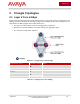
avaya.com 3. Triangle Topologies 3.1 Layer 2 Core & Edge Switch Clustering configuration with a single Switch Cluster Core and dual-connected edge devices. This topology represents a single VLAN spanning the edge devices. Multiple VLANs can be configured on the edge devices and 802.1Q tagged to the Switch Cluster Core.
avaya.com 3.2 Layer 3 Core (VRRP) & Layer 2 Edge Switch Clustering configuration with a single Switch Cluster Core and dual-connected edge devices. This topology represents different VLAN(s) spanning from each edge device(s) and those VLANs being routed at the Switch Cluster Core. Multiple VLANs can be configured on the edge devices and 802.1Q tagged to the Switch Cluster Core.
avaya.com 3.3 Layer 3 Core (RSMLT) & Layer 2 Edge Switch Clustering configuration with a single Switch Cluster Core and dual-connected edge devices. This topology represents different VLAN(s) spanning from each edge device(s) and those VLANs being routed at the Switch Cluster Core. Multiple VLANs can be configured on the edge devices and 802.1Q tagged to the Switch Cluster Core.
avaya.com 3.4 Layer 3 Core (RSMLT) & Layer 3 Edge Switch Clustering configuration with a single Switch Cluster Core and dual-connected edge devices. This topology represents routing from each the edge device(s) into the Switch Cluster Core.
avaya.com 3.5 Multicast Layer 2 Core (IGMP) & Edge (IGMP) Switch Clustering configuration with a single Switch Cluster Core and dual-connected edge devices. This topology represents a single VLAN spanning from each edge device(s). Multiple VLANs can be configured on the edge devices and 802.1Q tagged to the Switch Cluster Core.
avaya.com 3.6 Multicast Layer 3 Core (PIM-SM) & Layer 2 Edge (IGMP) Switch Clustering configuration with a single Switch Cluster Core and dual-connected edge devices. This topology represents different VLAN(s) spanning from each edge device(s) and those VLANs being routed at the Switch Cluster Core. Multiple VLANs can be configured on the edge devices and 802.1Q tagged to the Switch Cluster Core.
avaya.com 3.7 MSMLT Layer 3 Core (PIM-SM) & Edge (PIM-SM) Switch Clustering configuration with a single Switch Cluster Core and dual-connected edge devices. This topology represents different VLAN(s) spanning from each edge device(s) and those VLANs being routed at the Switch Cluster Core. Multiple VLANs can be configured on the edge devices and 802.1Q tagged to the Switch Cluster Core.
avaya.com 4. Square / Full Mesh Topologies 4.1 Layer 2 Core & Edge Switch Clustering configuration with two Switch Cluster Cores and dual-connected edge devices. This topology represents a single VLAN spanning the edge devices and the Switch Cluster Cores. Multiple VLANs can be configured on the edge devices and 802.1Q tagged to the Switch Cluster Core.
avaya.com Switch Cluster Core 1 Switch Cluster Square Core 2 Topology VSP 9000 VSP 9000 VSP 9000 ERS 8800/8600 VSP 9000 ERS 8300 VSP 9000 ERS 5000 Full Mesh Topology Notes Standalone and Stack ERS 5000 Full Mesh requires 6.1 or later. ERS 8800/8600 VSP 9000 ERS 8800/8600 ERS 8800/8600 ERS 8800/8600 ERS 8300 ERS 8800/8600 ERS 5000 Standalone and Stack ERS 5000 Full Mesh requires 6.1 or later.
avaya.com 4.2 Layer 3 Core (RSMLT/VRRP) & Layer 2 Edge Scenario 1 Switch Clustering configuration with two Switch Cluster Cores and dual-connected edge devices. This topology represents different VLANs spanning the edge devices and the Switch Cluster Cores. Only one of the Switch Cluster Cores performs Layer 3 routing, while the other is strictly Layer 2. Multiple VLANs can be configured on the edge devices and 802.1Q tagged to the Switch Cluster Cores.
avaya.com Switch Cluster Core 1 Switch Cluster Square Core 2 Topology VSP 9000 VSP 9000 VSP 9000 ERS 8800/8600 VSP 9000 ERS 8300 VSP 9000 ERS 5000 Full Mesh Topology Notes Standalone and Stack ERS 5000 Full Mesh requires 6.1 or later. ERS 8800/8600 VSP 9000 ERS 8800/8600 ERS 8800/8600 ERS 8800/8600 ERS 8300 ERS 8800/8600 ERS 5000 Standalone and Stack ERS 5000 Full Mesh requires 6.1 or later.
avaya.com 4.3 Layer 3 Core (RSMLT/VRRP) & Layer 2 Edge Scenario 2 Switch Clustering configuration with two Switch Cluster Cores and dual-connected edge devices. This topology represents different VLANs spanning the edge devices and the Switch Cluster Cores. Each Switch Cluster Cores performs routing and uses RSMLT between the Switch Cluster cores running in conjunction with Static, RIP, OSPF, or BGP. Multiple VLANs can be configured on the edge devices and 802.1Q tagged to the Switch Cluster Cores.
avaya.com Switch Cluster Core 1 Switch Cluster Square Core 2 Topology VSP 9000 VSP 9000 VSP 9000 ERS 8800/8600 VSP 9000 ERS 8300 Full Mesh Topology Notes ERS 8300 RSMLT support requires Release 4.1.0.0 or later. ERS 8300 RSMLT Edge support requires Release 4.1.4.0 or later. ERS 8800/8600 VSP 9000 ERS 8800/8600 ERS 8800/8600 ERS 8800/8600 ERS 8300 ERS 8300 RSMLT support requires Release 4.1.0.0 or later.
avaya.com 4.4 Multicast Layer 2 Core (IGMP) & Edge (IGMP) Switch Clustering configuration with two Switch Cluster Cores and dual-connected edge devices. This topology represents a single VLAN spanning from each edge device(s). Multiple VLANs can be configured on the edge devices and 802.1Q tagged to the Switch Cluster Core.
avaya.com Switch Cluster Core 1 Switch Cluster Square Core 2 Topology VSP 9000 VSP 9000 VSP 9000 ERS 8800/8600 VSP 9000 ERS 8300 ERS 8800/8600 VSP 9000 ERS 8800/8600 ERS 8800/8600 ERS 8800/8600 ERS 8300 ERS 8800/8600 ERS 1600 ERS 8300 VSP 9000 ERS 8300 ERS 8800/8600 ERS 8300 ERS 8300 ERS 1600 ERS 8800/8600 ERS 1600 ERS 1600 Full Mesh Topology Notes ERS 8300 IGMP Querier Requires Release 4.0.x or later.
avaya.com 4.5 MSMLT Layer 3 Core (PIM-SM) & Layer 2 Edge (IGMP) Scenario 1 Switch Clustering configuration with two Switch Cluster Cores and dual-connected edge devices. This topology represents different VLANs spanning the edge devices and the Switch Cluster Cores. Only one of the Switch Cluster Cores performs Layer 3 multicast routing, while the other is strictly Layer 2. Multiple VLANs can be configured on the edge devices and 802.1Q tagged to the Switch Cluster Cores.
avaya.com Switch Cluster Core 1 Switch Cluster Square Core 2 Topology VSP 9000 VSP 9000 VSP 9000 ERS 8800/8600 VSP 9000 ERS 8300 ERS 8800/8600 ERS 8800/8600 ERS 8800/8600 ERS 8300 ERS 8800/8600 ERS 1600 Full Mesh Topology Notes Table 4.
avaya.com 4.6 MSMLT Layer 3 Core (PIM-SM) & Layer 2 Edge (IGMP) Scenario 2 Switch Clustering configuration with two Switch Cluster Cores and dual-connected edge devices. This topology represents different VLANs spanning the edge devices and the Switch Cluster Cores. Both of the Switch Cluster Cores performs Layer 3 multicast routing, while the edge device(s) are Layer 2 IGMP. Multiple VLANs can be configured on the edge devices and 802.1Q tagged to the Switch Cluster Cores.
avaya.com Switch Cluster Core 1 Switch Cluster Square Core 2 Topology VSP 9000 VSP 9000 VSP 9000 ERS 8800/8600 ERS 8800/8600 VSP 9000 ERS 8800/8600 ERS 8800/8600 Full Mesh Topology Notes Table 4.6 – Square / Mesh MSMLT Layer 3 Core (PIM-SM) & Layer 2 Edge (IGMP) Scenario 2 Additional Notes: 1) The ERS 5000 does not support IGMP over SMLT/SLT at this time and therefore cannot be used as a Switch Cluster Core in this topology.
avaya.com 4.7 MSMLT Layer 3 Core (PIM-SM) & Edge (PIM-SM) Switch Clustering configuration with two Switch Cluster cores and dual-connected edge devices. This topology represents different VLANs spanning the edge devices and the Switch Cluster Cores. Both of the Switch Cluster Cores as well as the edge device(s) performs Layer 3 multicast routing. Multiple VLANs can be configured on the edge devices and 802.1Q tagged to the Switch Cluster Cores.
avaya.com Switch Cluster Core 1 Switch Cluster Square Core 2 Topology VSP 9000 VSP 9000 VSP 9000 ERS 8800/8600 ERS 8800/8600 VSP 9000 ERS 8800/8600 ERS 8800/8600 Full Mesh Topology Notes Table 4.7 – Square / Mesh MSMLT Layer 3 Core (PIM-SM) & Edge (PIM-SM) Additional Notes: 1) The ERS 5000 does not support IGMP over SMLT/SLT at this time and therefore cannot be used as a Switch Cluster Core in this topology.
avaya.com 5. Switch Clustering – Best Practice Feature Support With the implementation of Switch Clustering, there are several protection features that are recommended for use to ensure a solid and resilient infrastructure.
avaya.com 6. Reference Documentation For more detailed information on Switch Clustering, please refer to: Publication Number Document Title (NN48500-573) Small Campus Technical Solutions Guide (NN48500-574) Medium Campus Technical Solutions Guide (NN48500-575) Large Campus Technical Solutions Guide (NN48500-609) Super Large Campus Technical Solutions Guide (NN48500-518) Switch Clustering using SMLT Technical Configuration Guide © 2011 Avaya Inc. All Rights Reserved.